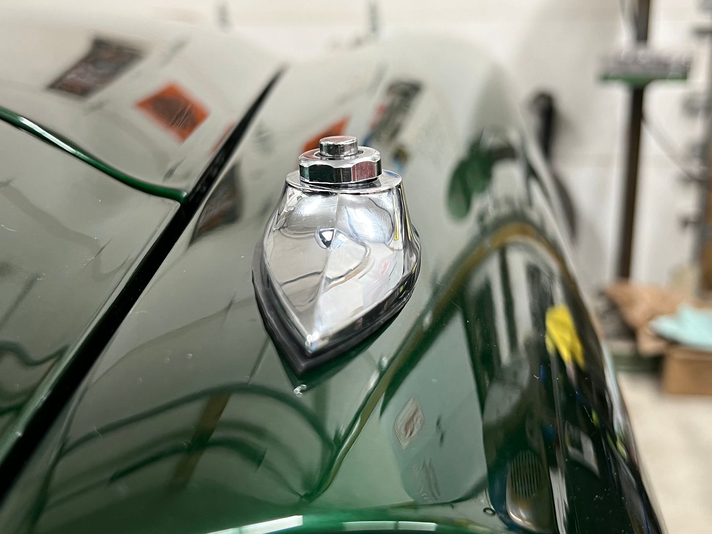
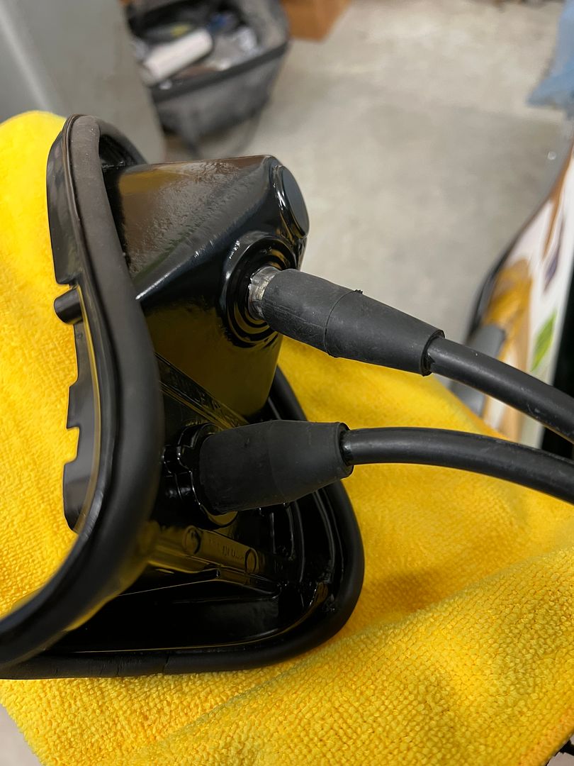
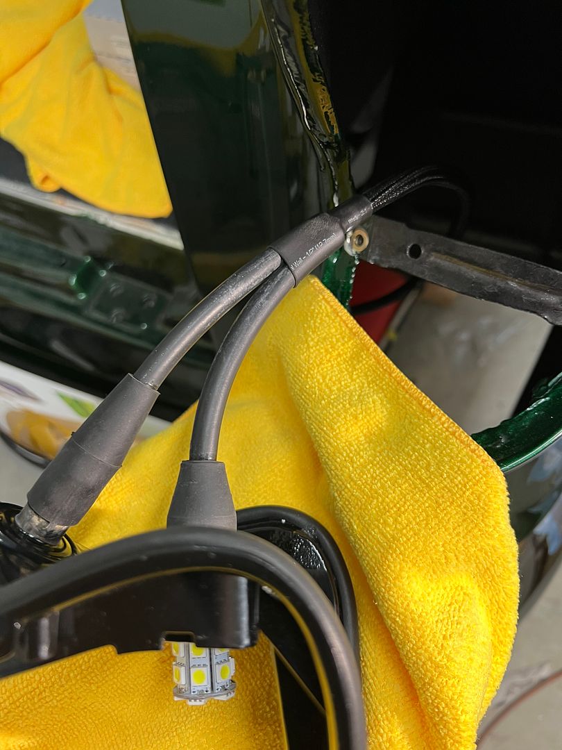
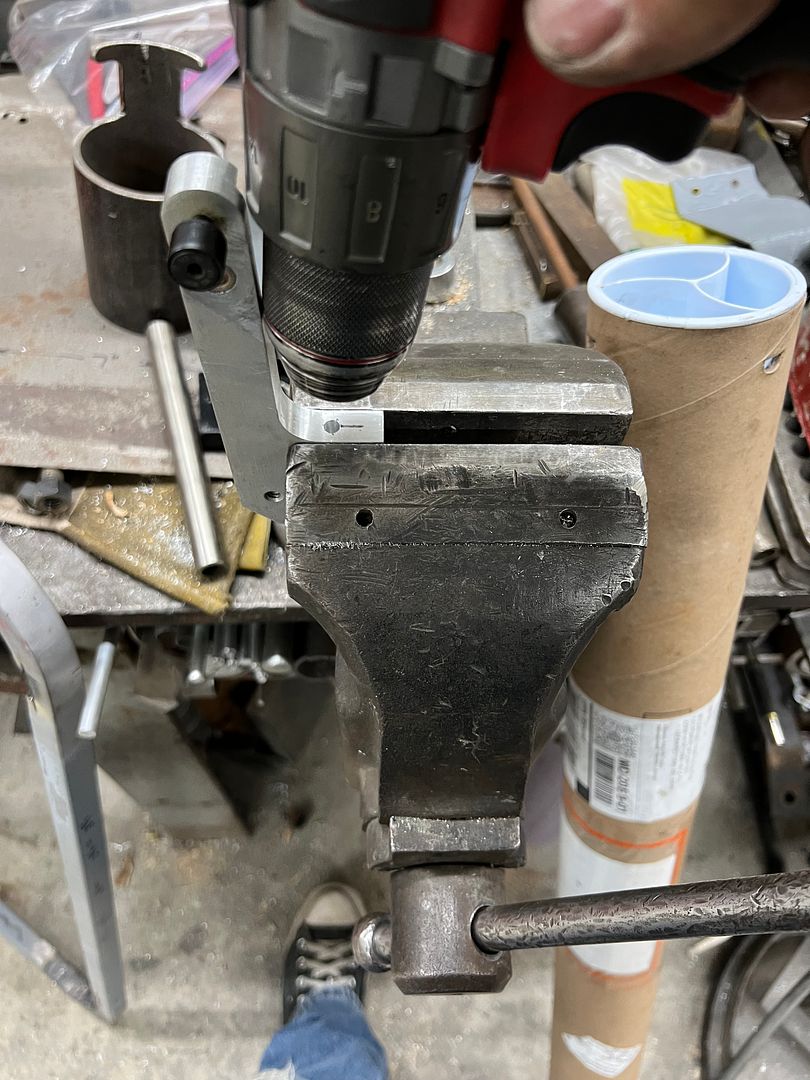
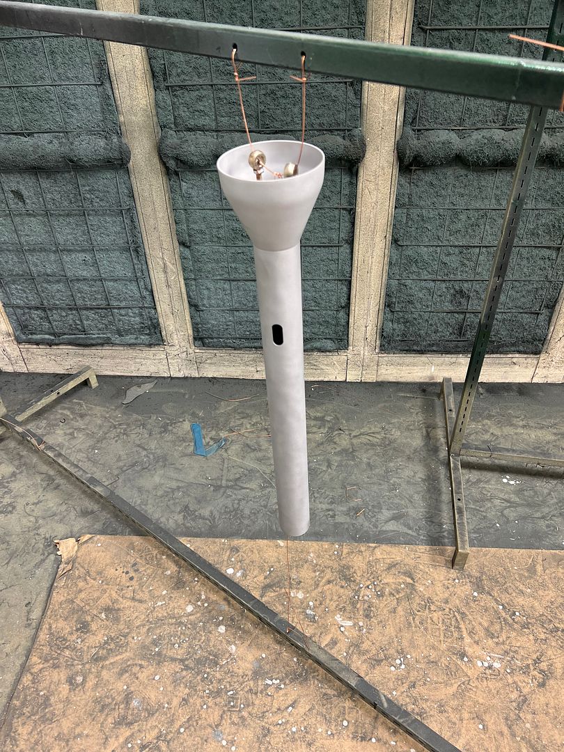
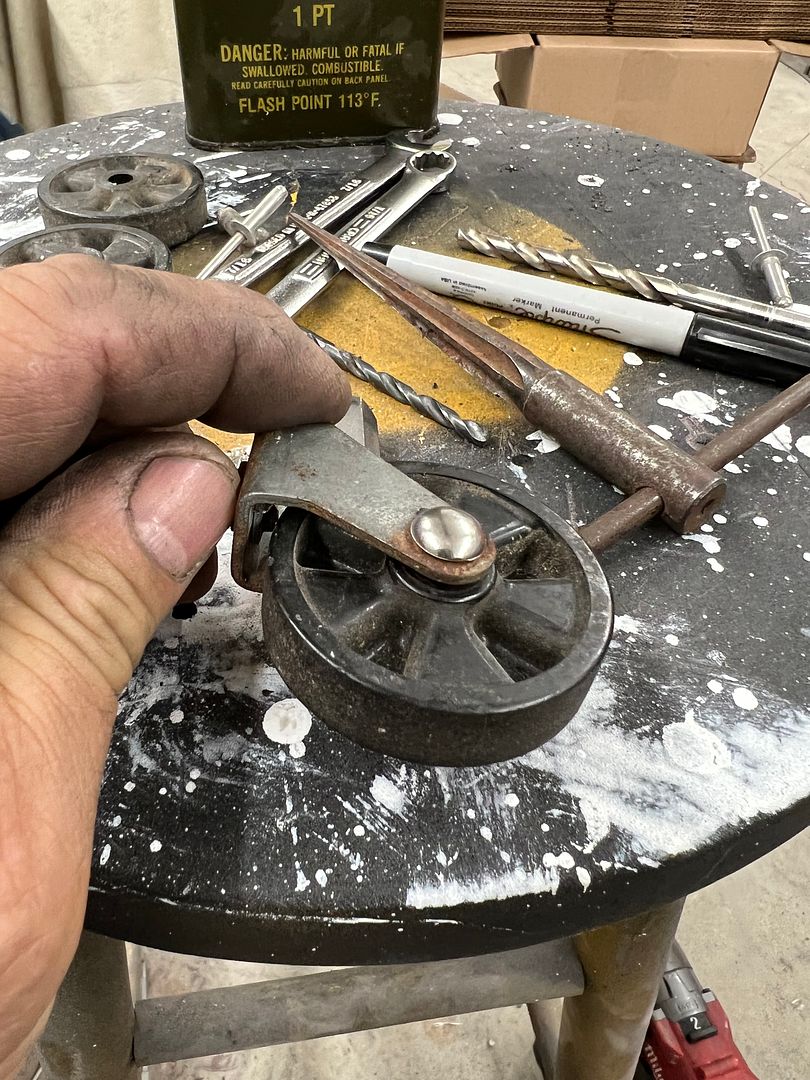
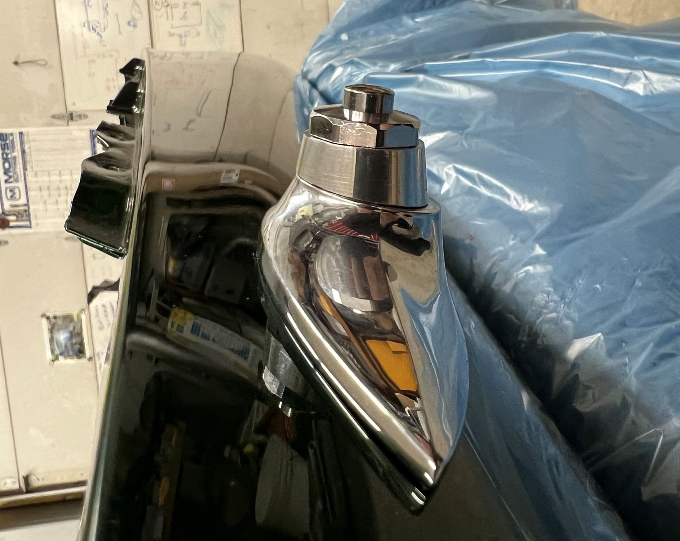
More progress, we were test fitting the power antenna an noticed that the mounting bezel did not sit horizontally on the fender. I had quickly whipped up a wedge shaped and tapered spacer out of some aluminum as a quick test.
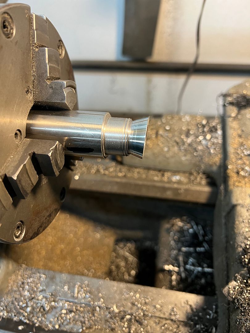
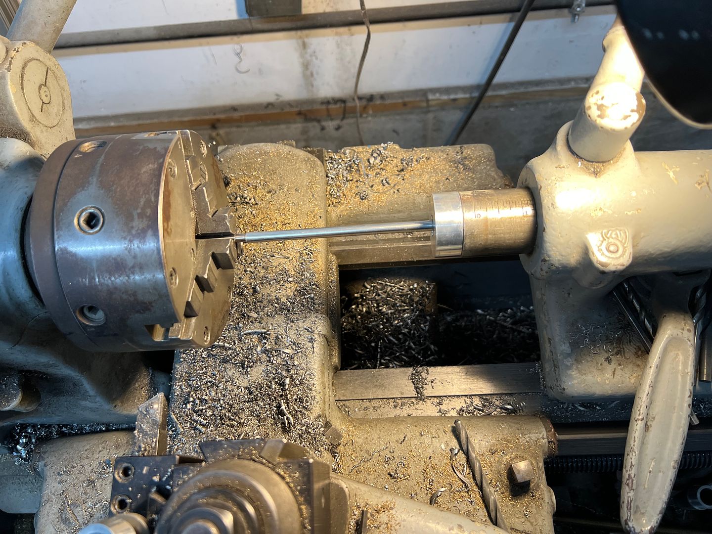
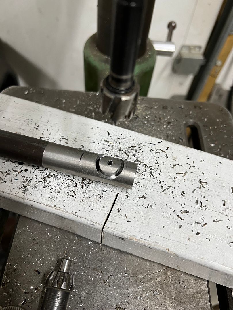
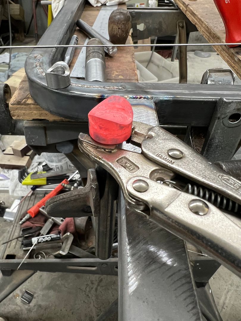
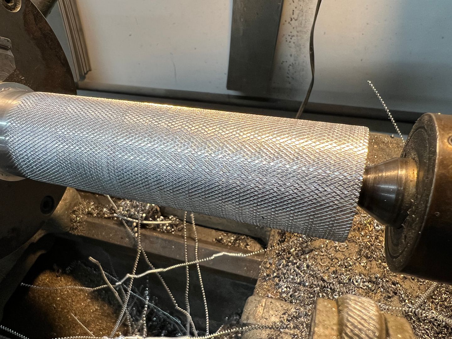
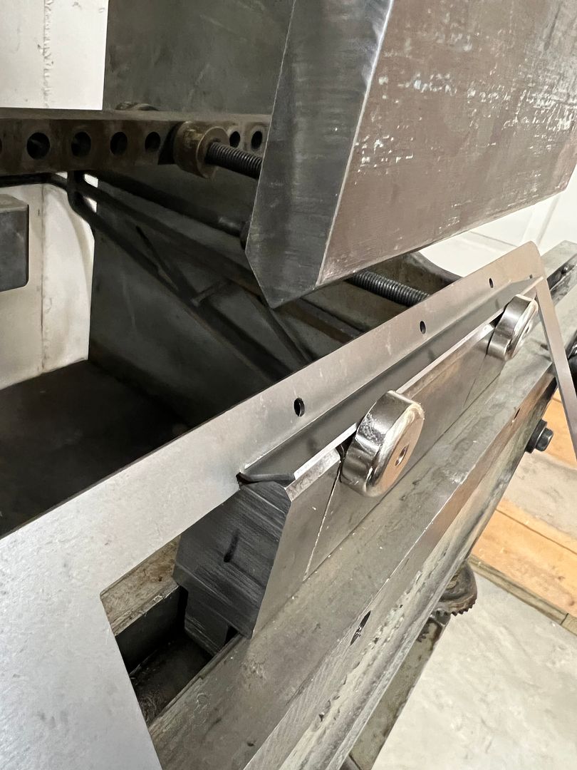
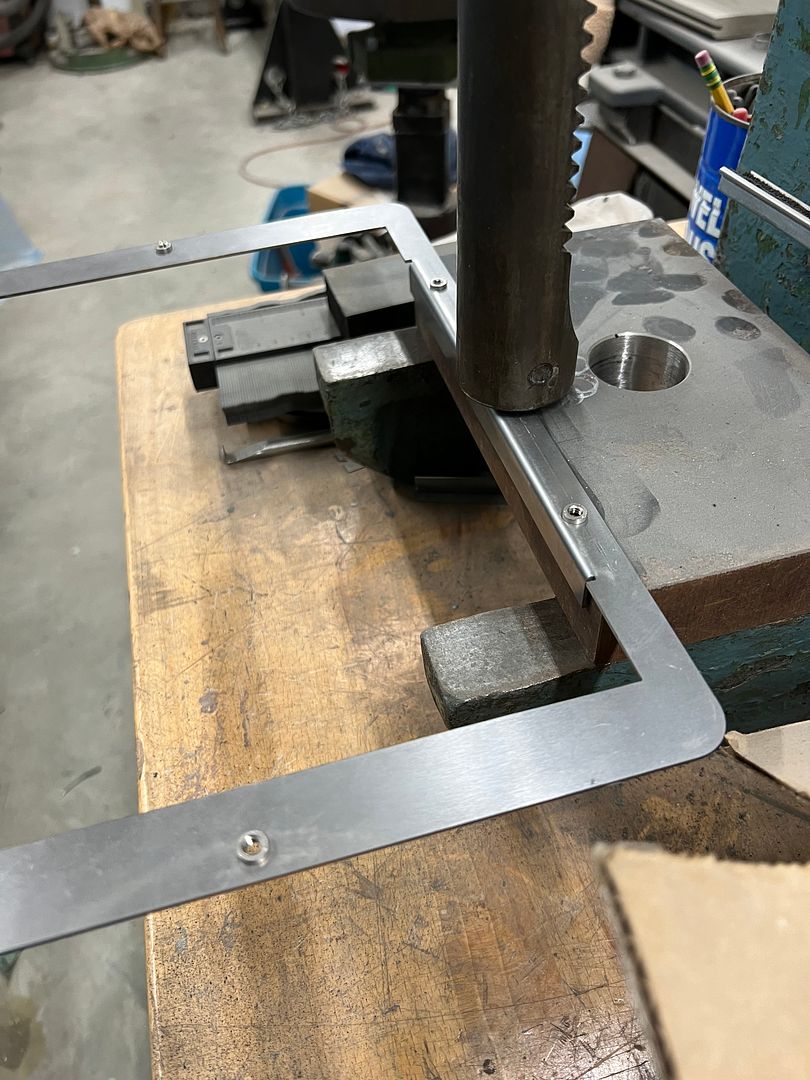
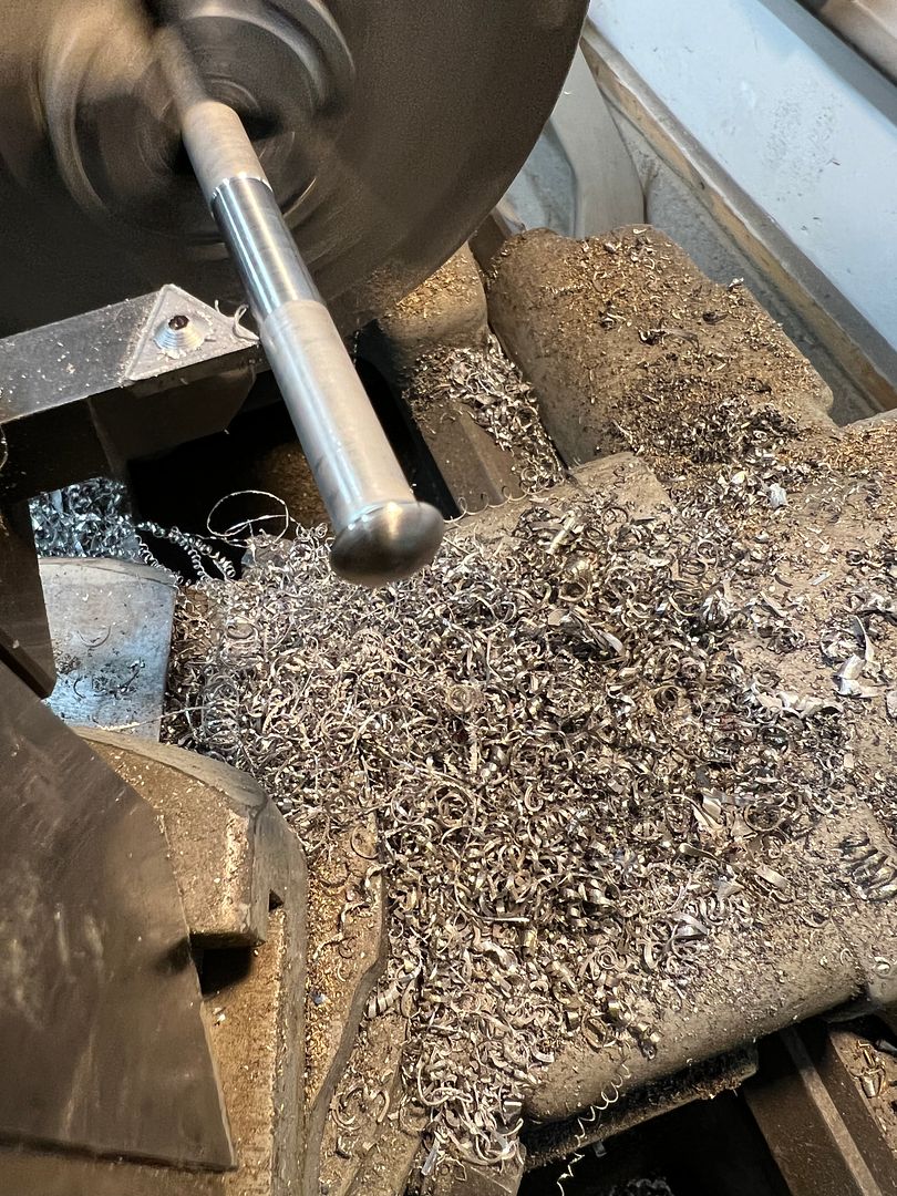
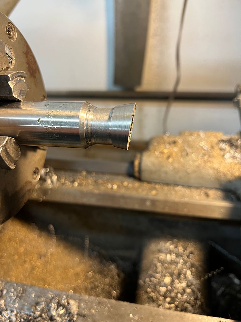
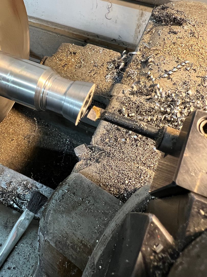
Where that was functional, it did not match the chrome finish of the bezel. I picked up a chunk of 1" stainless rod (local drop cut) to make a duplicate out of stainless. The wedge shape was added first, using the 12" disc sander... then clamped in the Southbend for the taper cut and a hole boring.
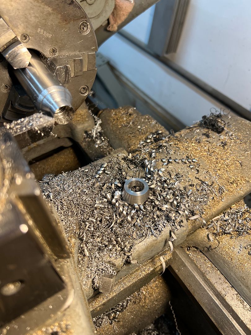
....and trimmed off to length
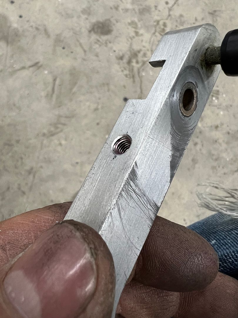
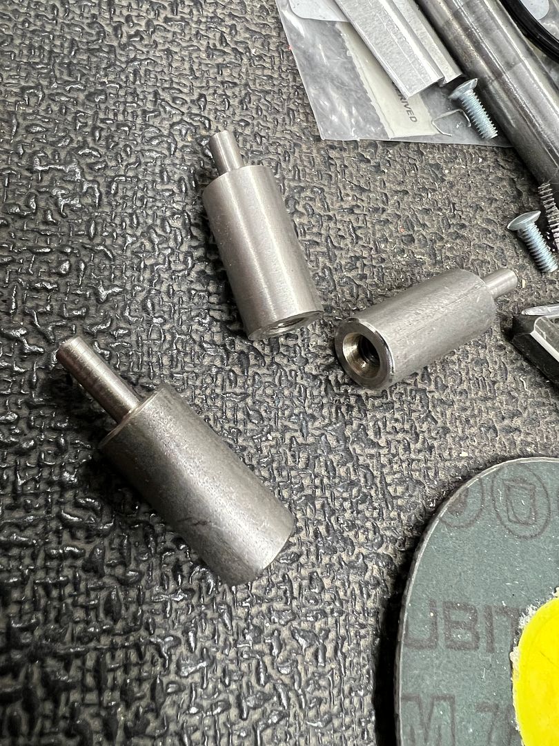
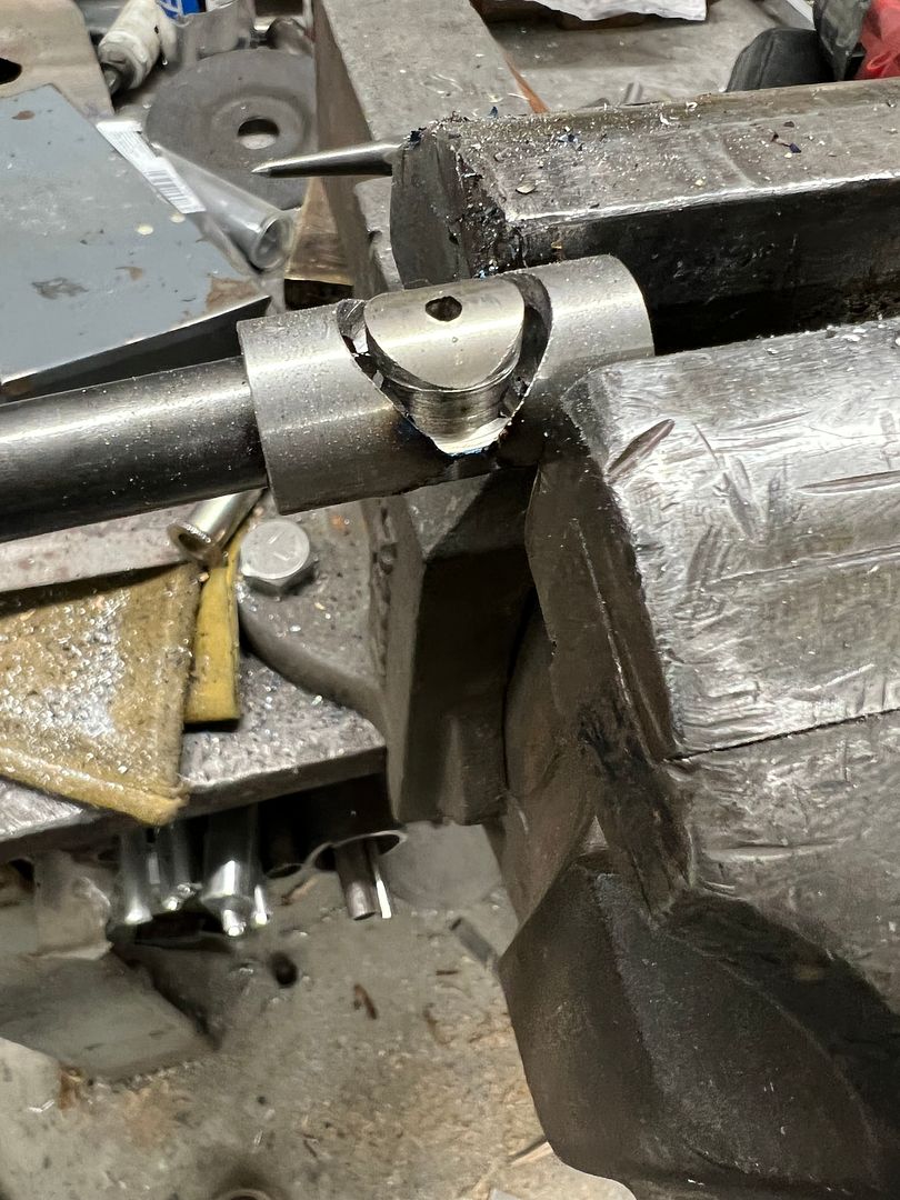
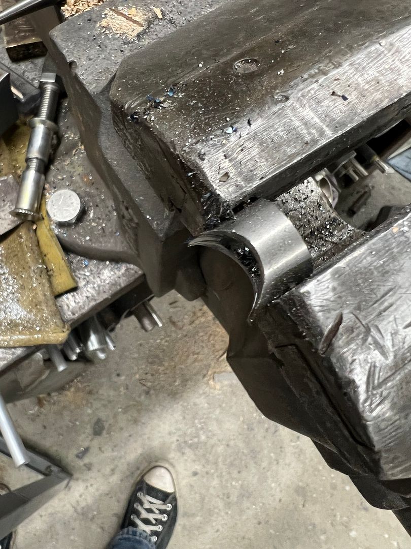
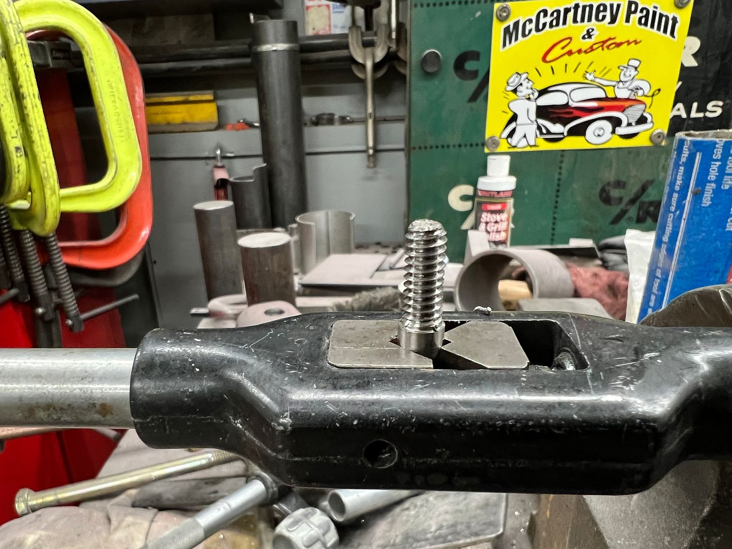
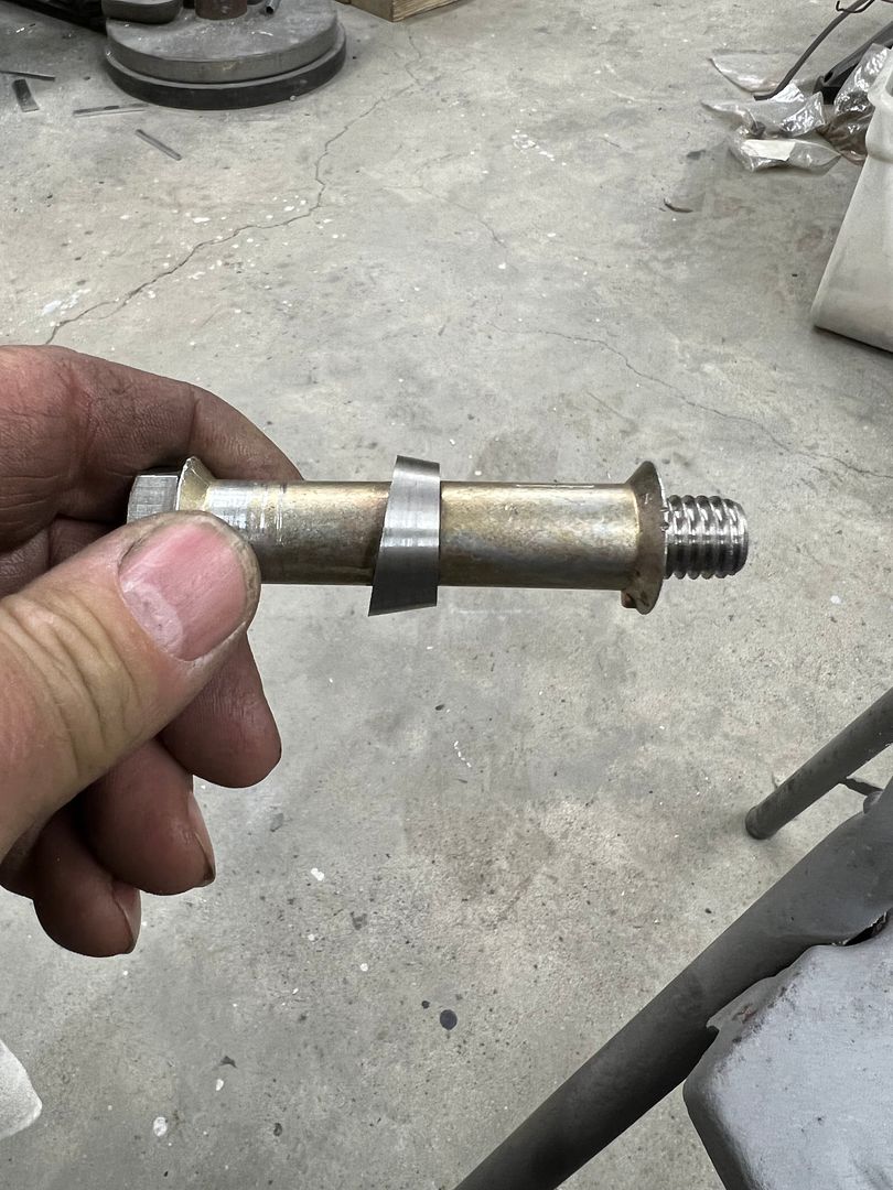
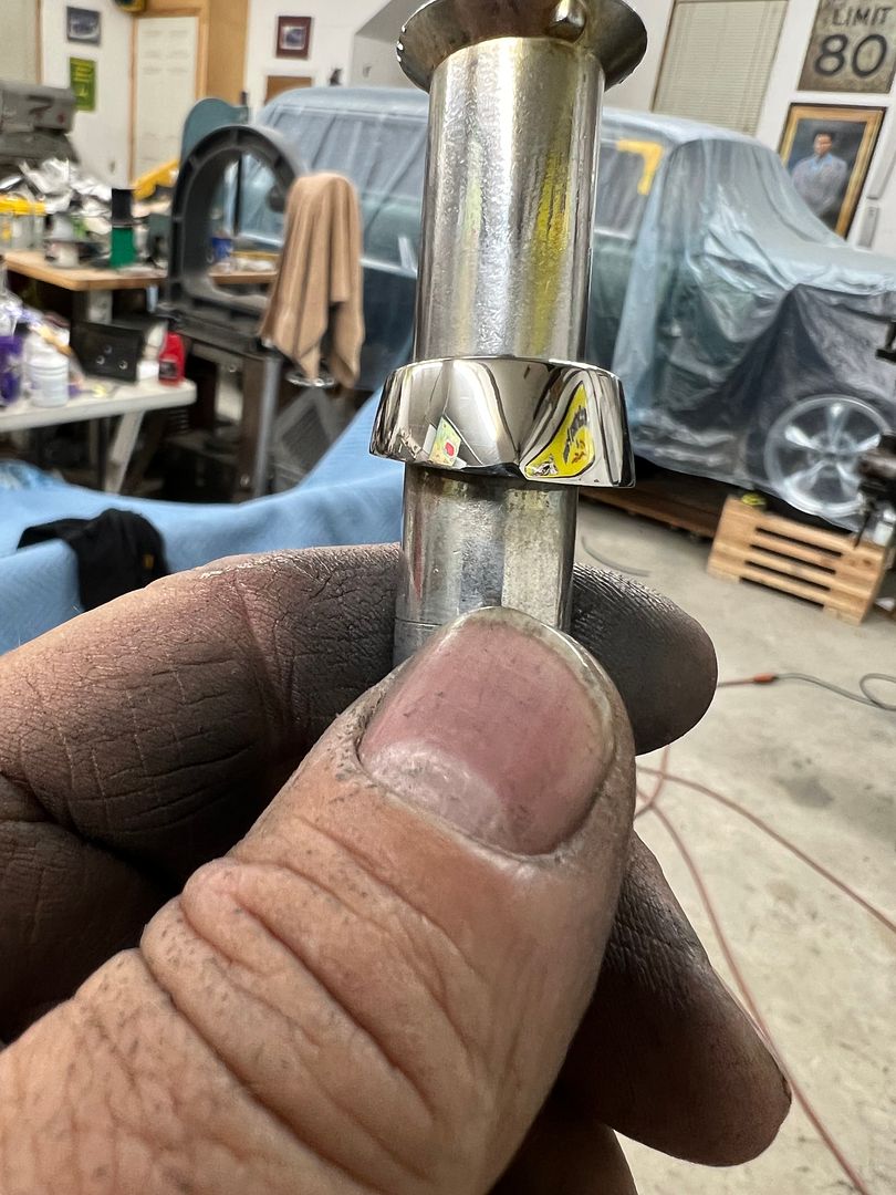
In order to hold this oddball shape for polishing, some rivnuts were used on a 1/2-13 bolt, with the wedge angle added to one for a more positive hold..
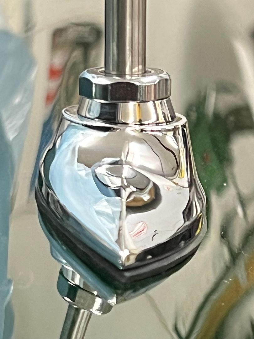
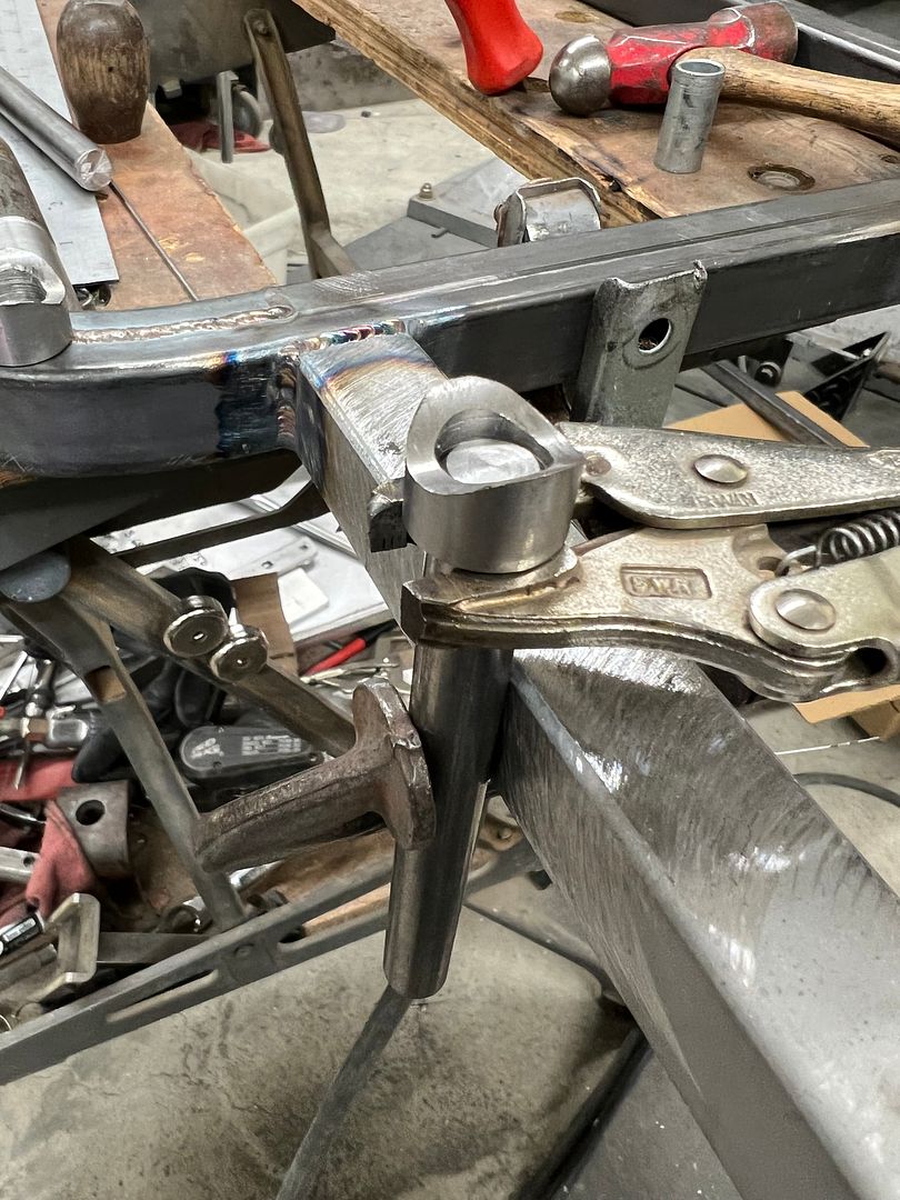
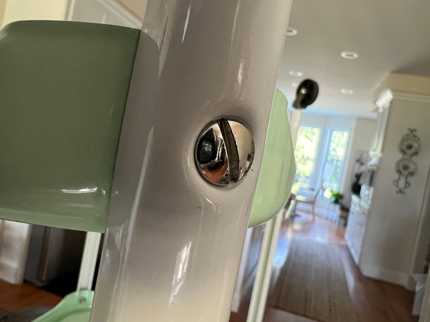
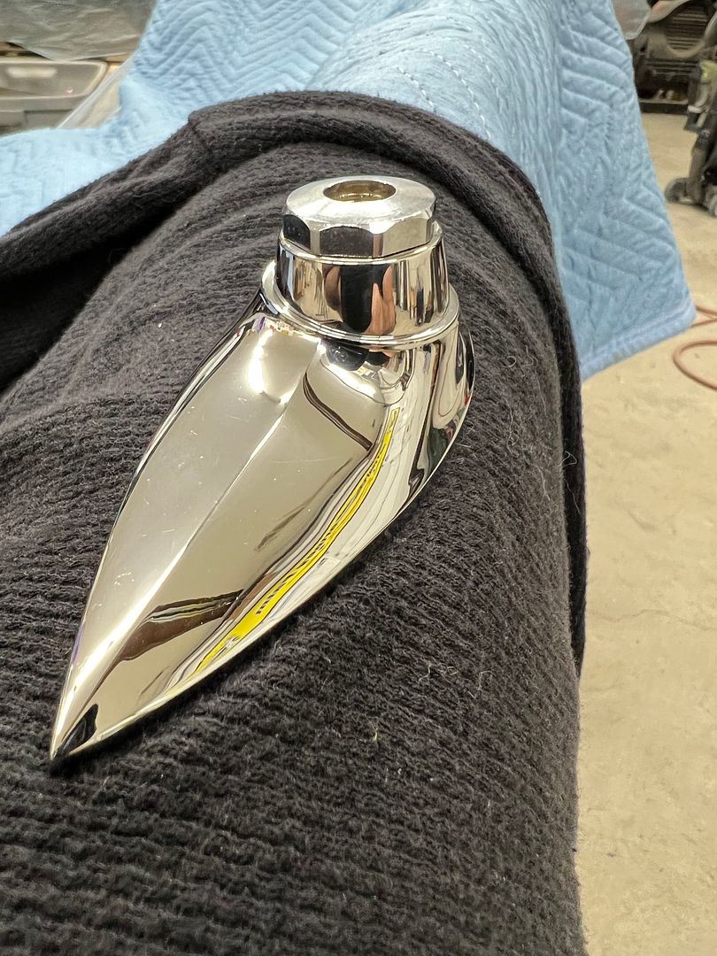
Completed, this matches the chrome finish of the bezel much better...
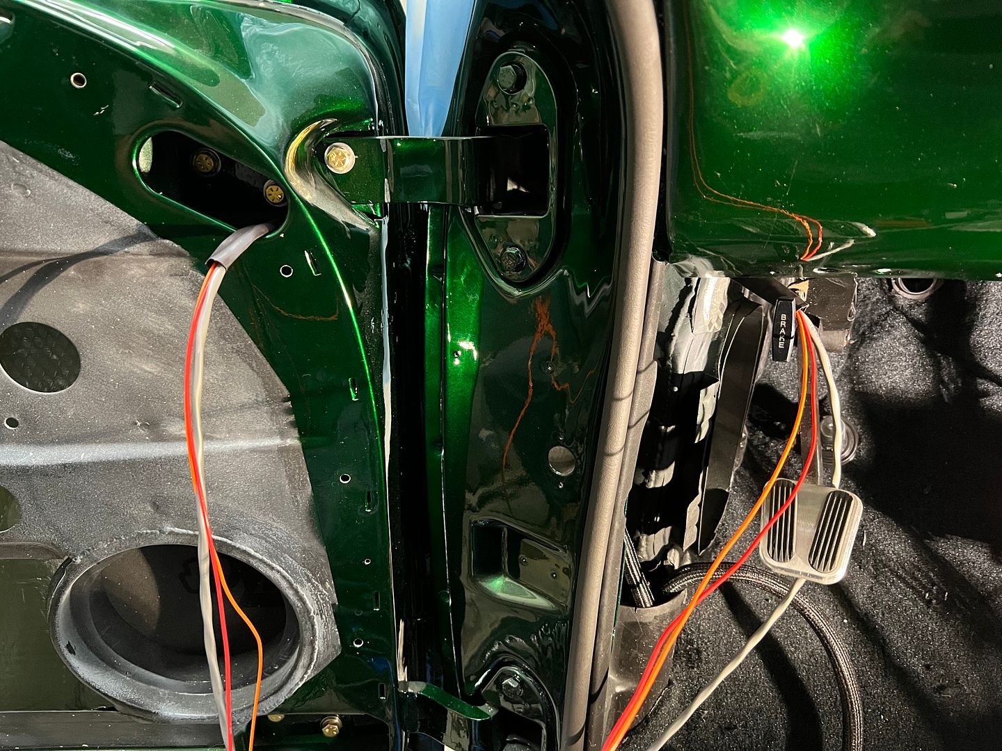
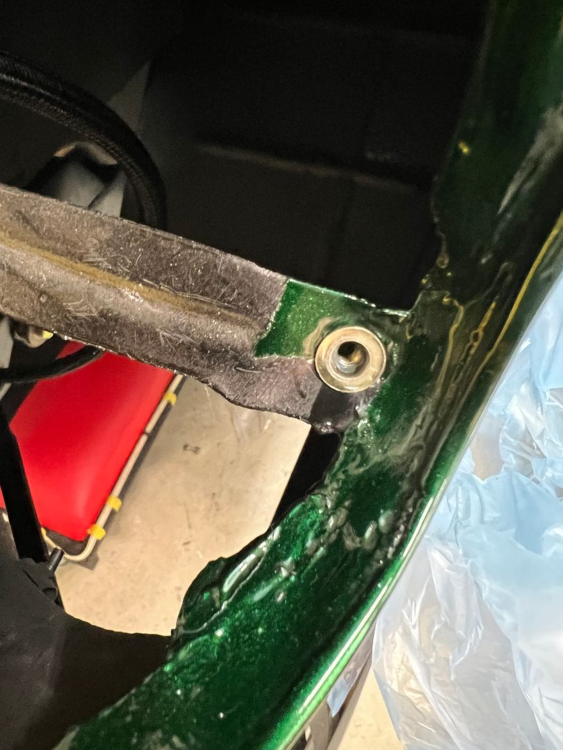
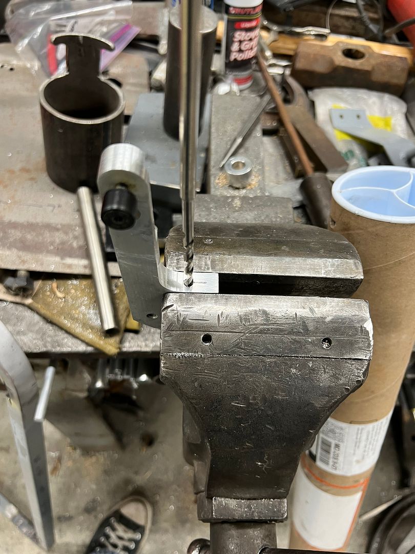
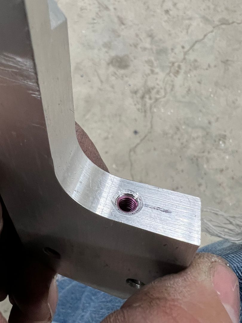
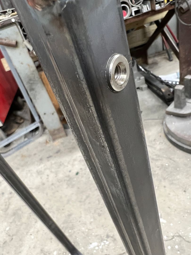
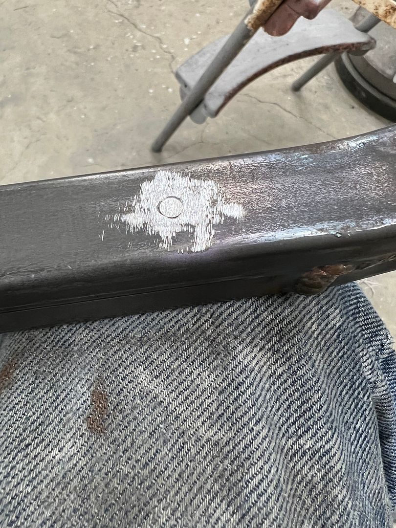
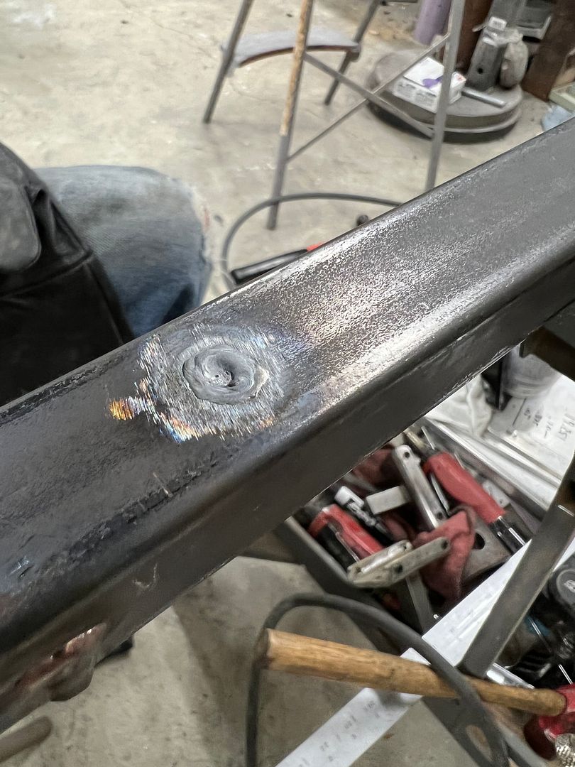
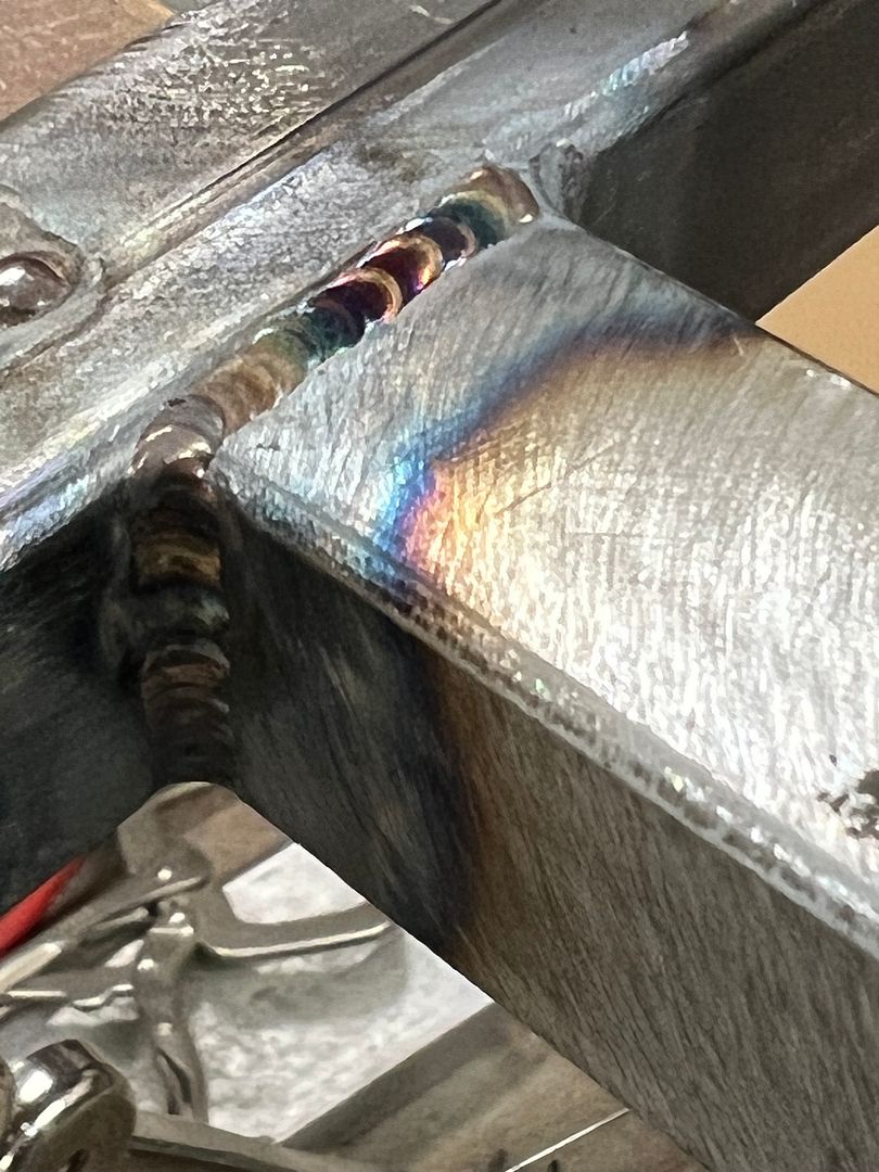
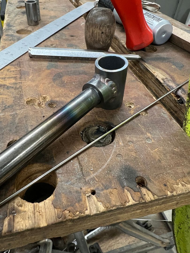
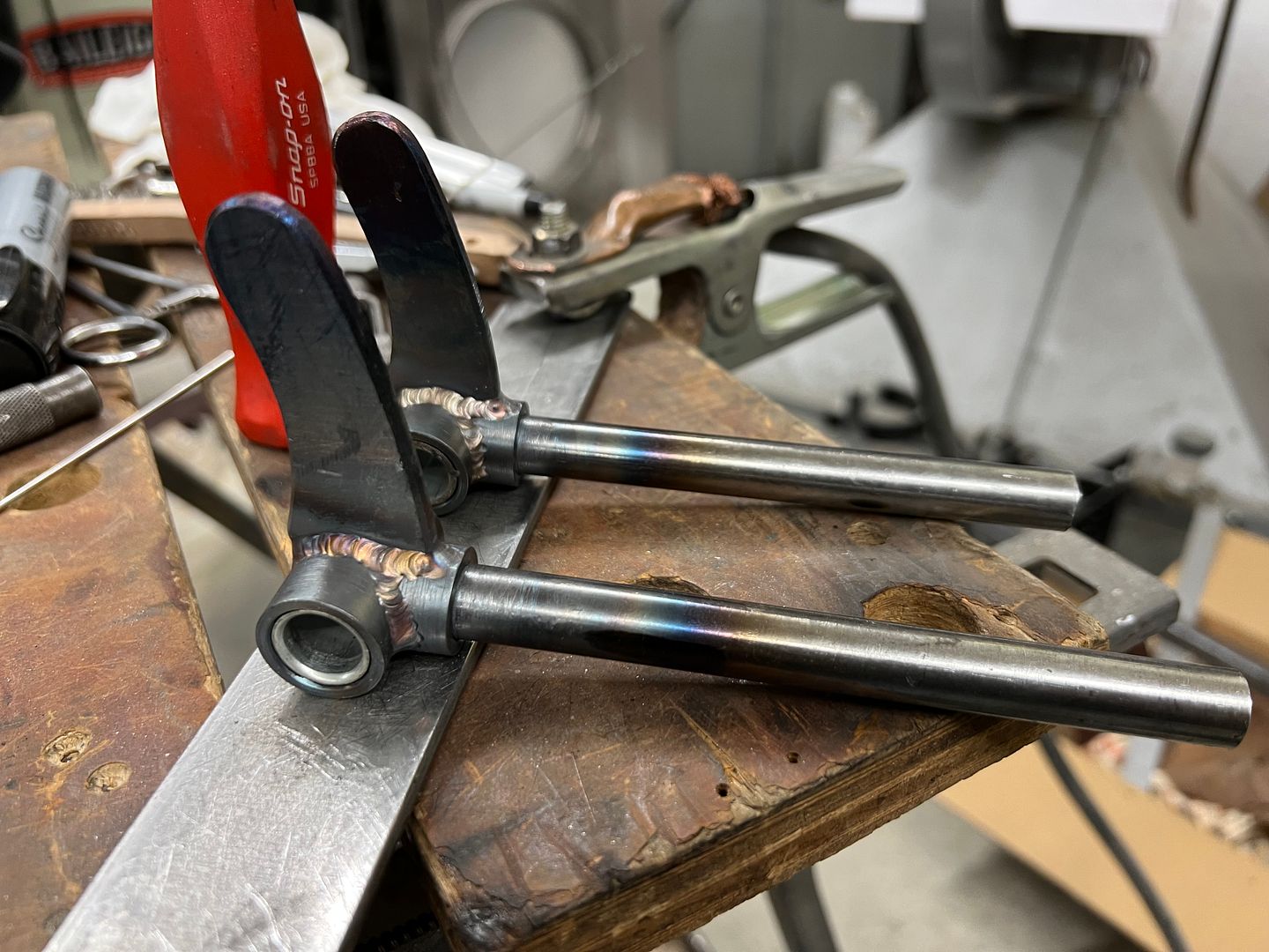
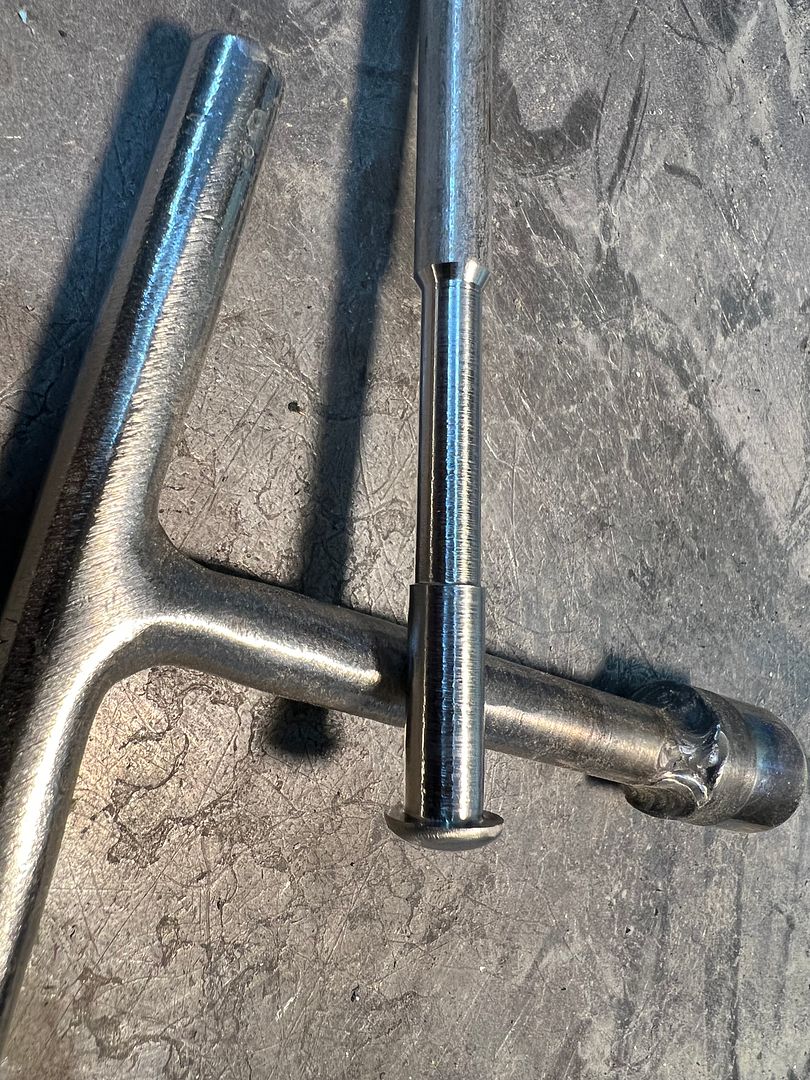
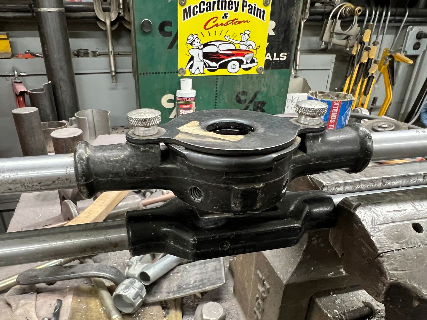
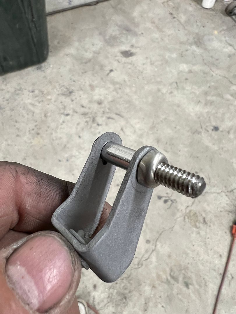
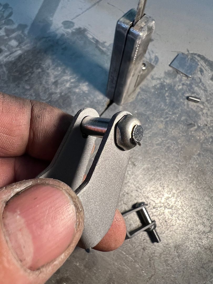
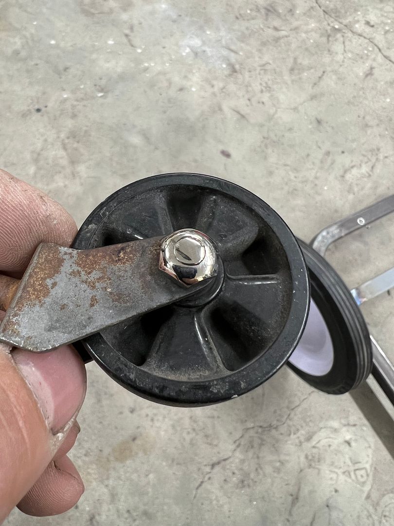
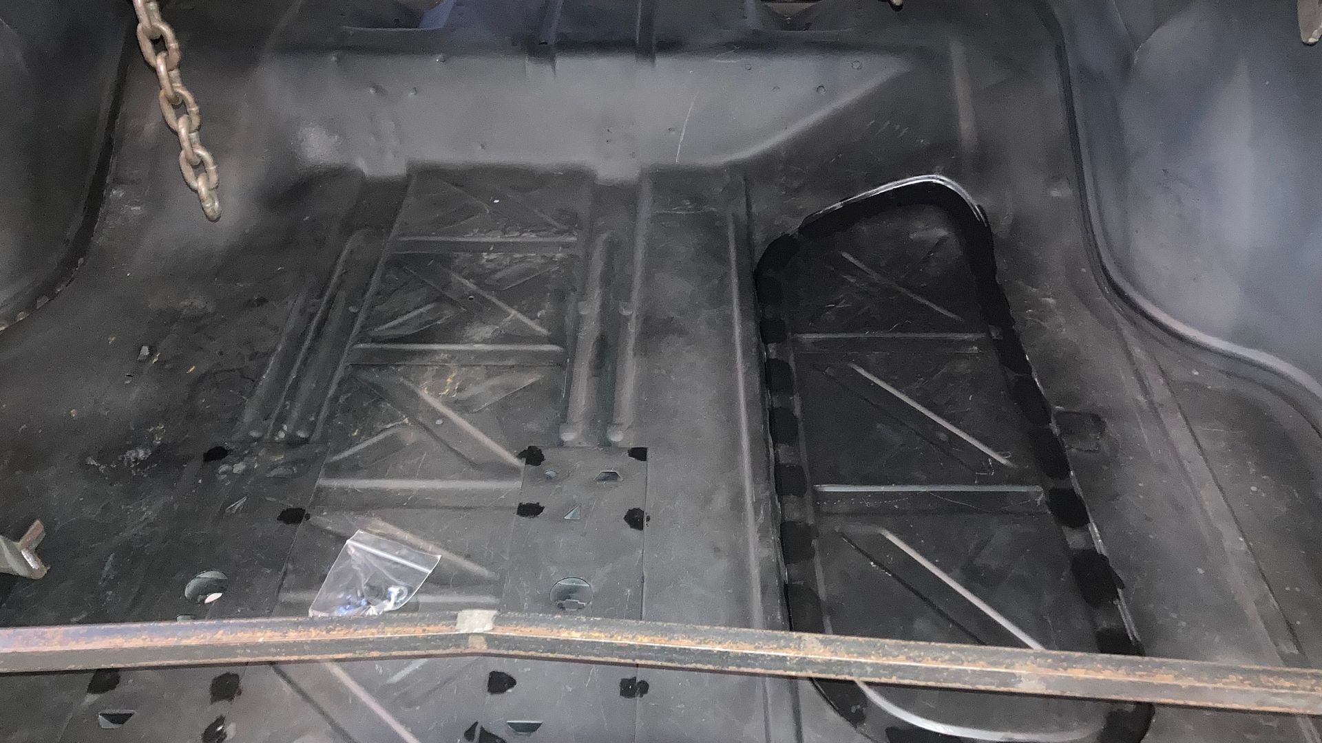
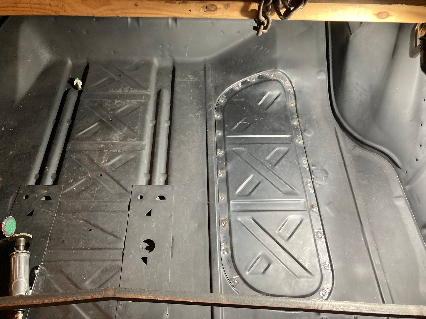
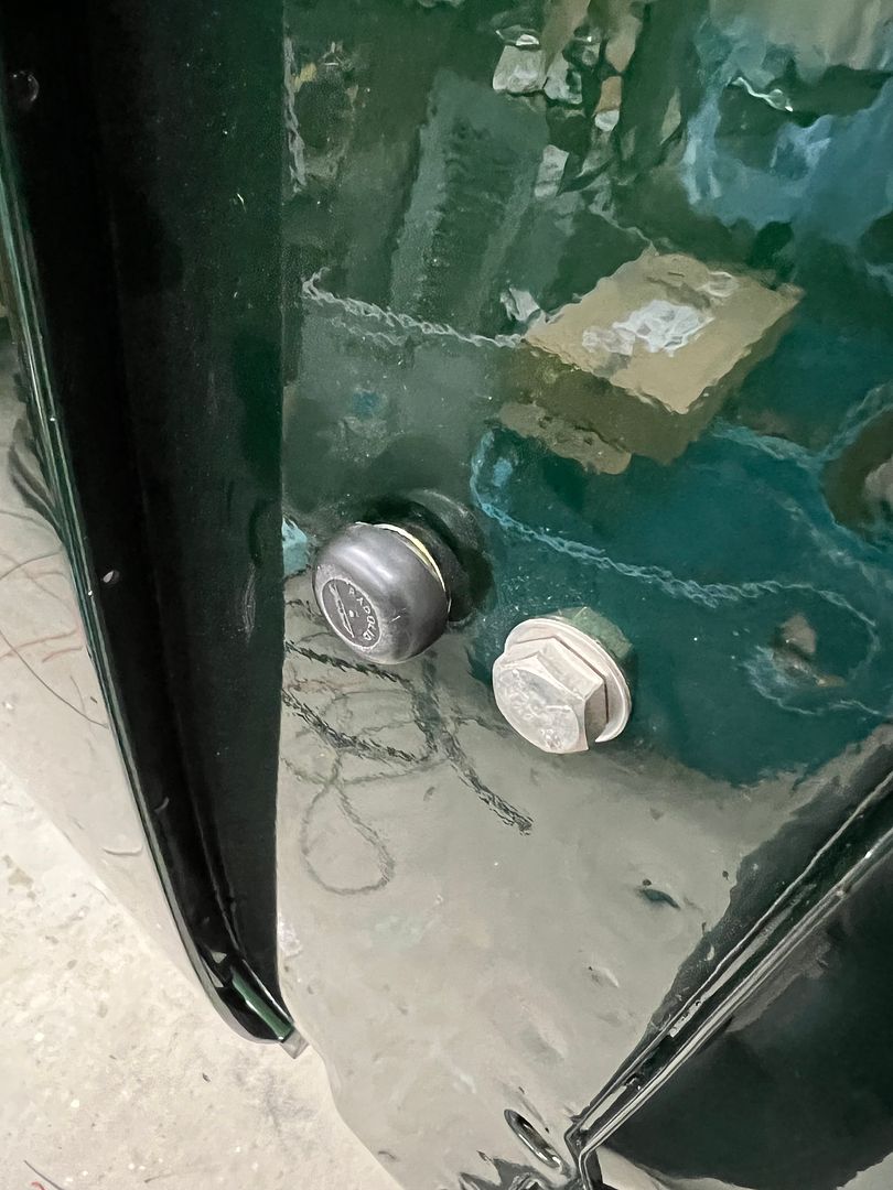
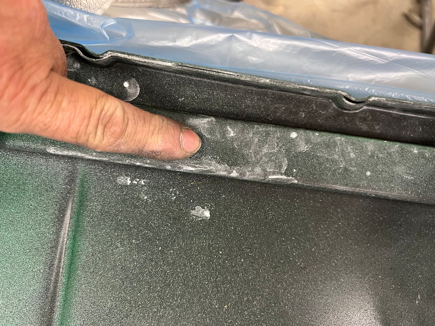
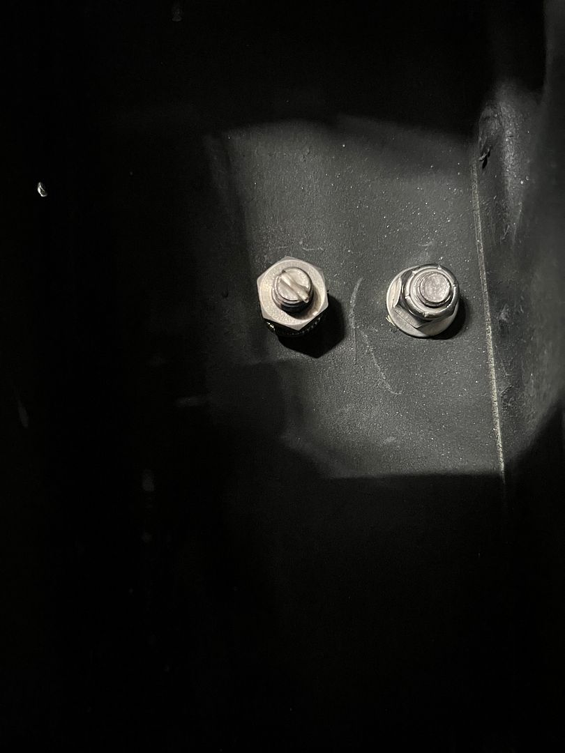
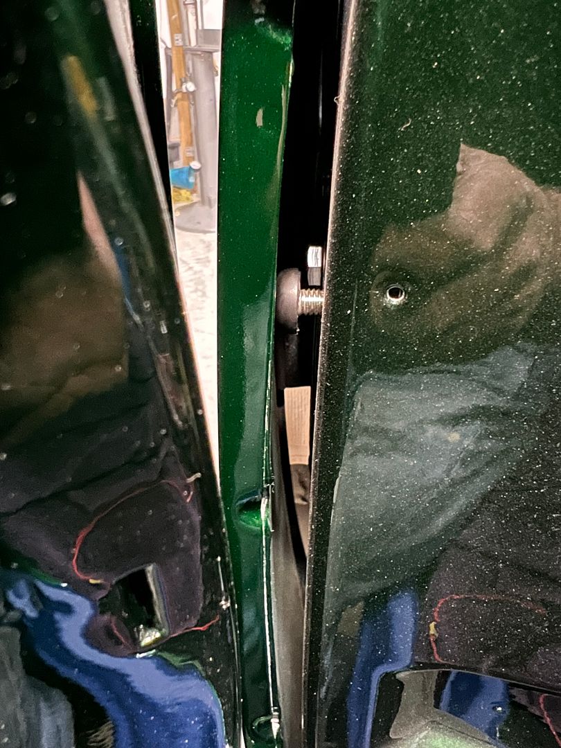
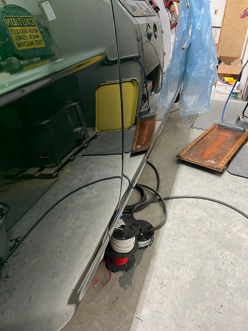
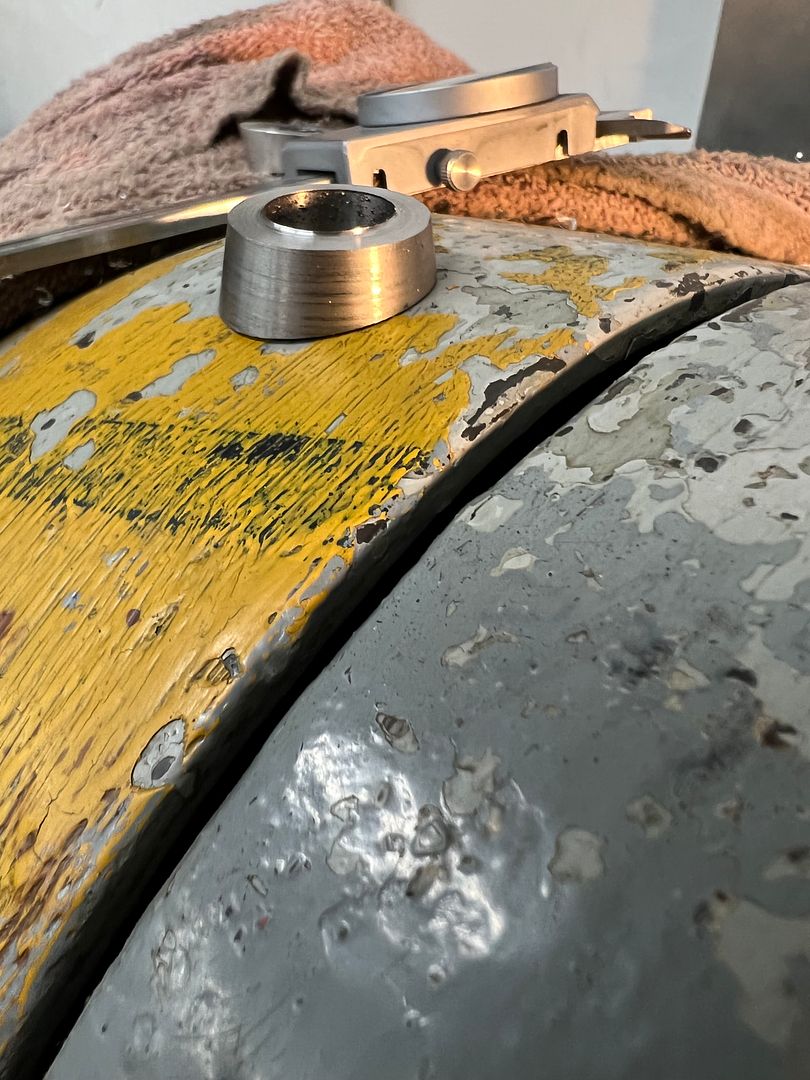
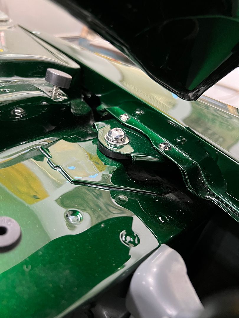
Since we were ready to re-install the front fenders, I thought I'd grab pictures of our fine-tuning adjustment screws for the fender to door alignment. The hex bolt shown on the right is filling an existing hole that used to have a rubber plug in it. I guess having pulled out the dried and cracked old rubber plug, I wanted a more permanent solution. We were going to use that hole but it did not align with the rib on the fender's rear brace. So another hole was drilled next to it, a 3/8-16 AVK style rivet nut installed, and a fully threaded bolt added. The bolt head was covered with a rubber cap and the inside end of the bolt had a slot added for adjustment purposes. Now we could use a screwdriver to adjust the screw outward, pushing the center of the fender until it aligns to the door surface.. A jam nut on the inside tightens against the rivnut to prevent any movement.
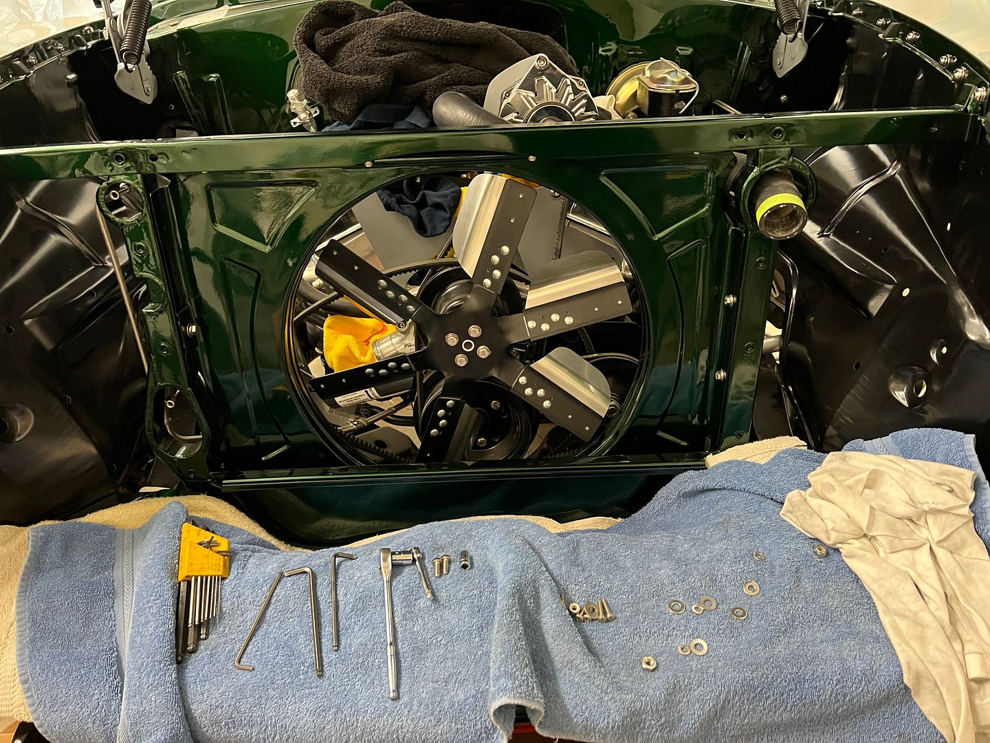
And with our upper fender mounts painted, they get installed using polished button head hardware and our barely noticeable shims we had fabricated.
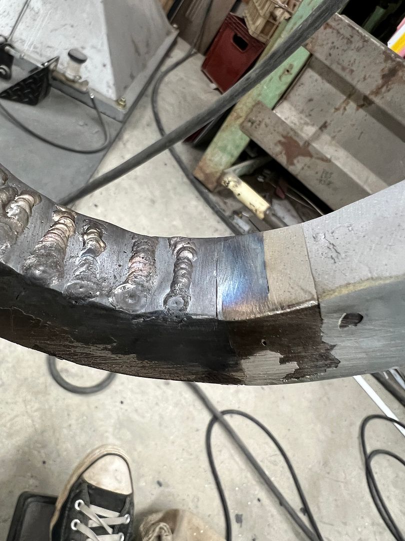
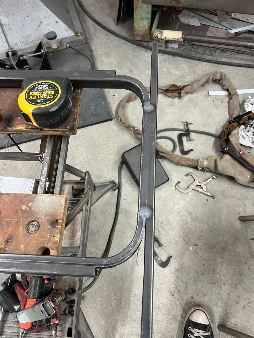
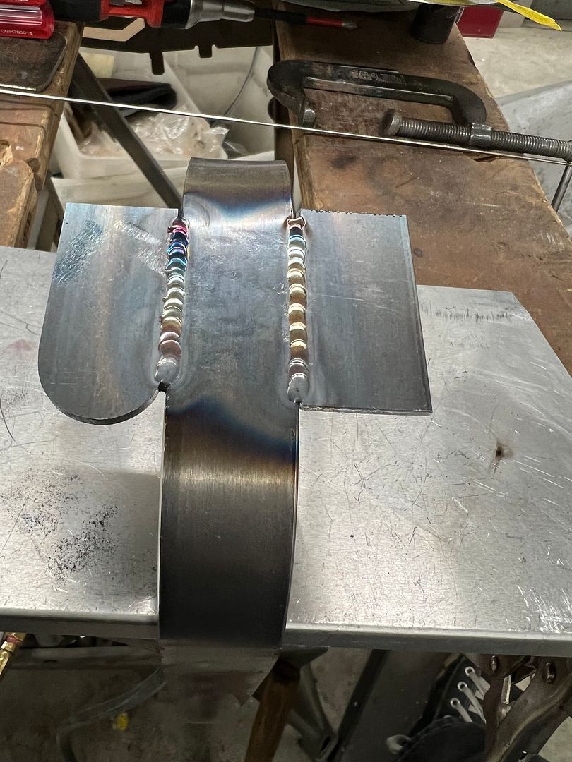
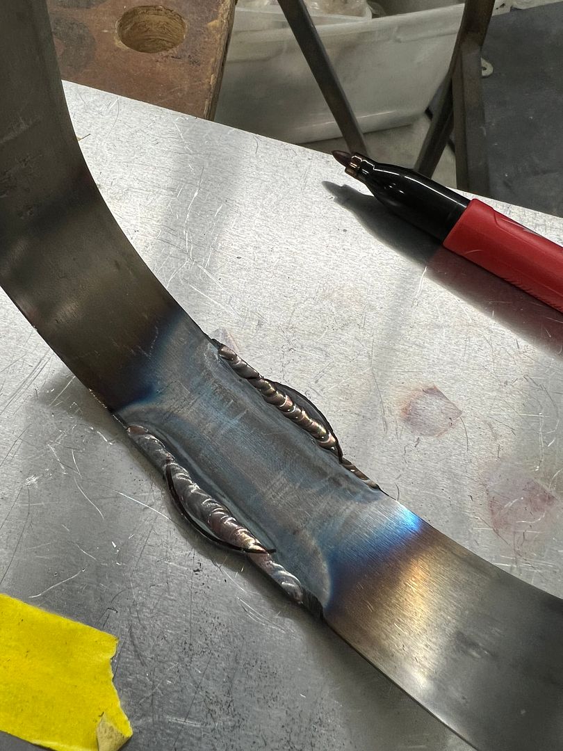
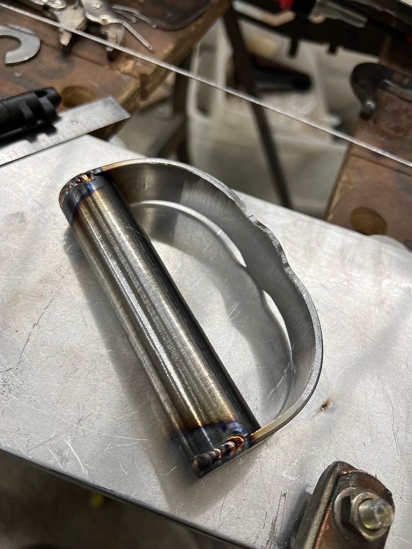
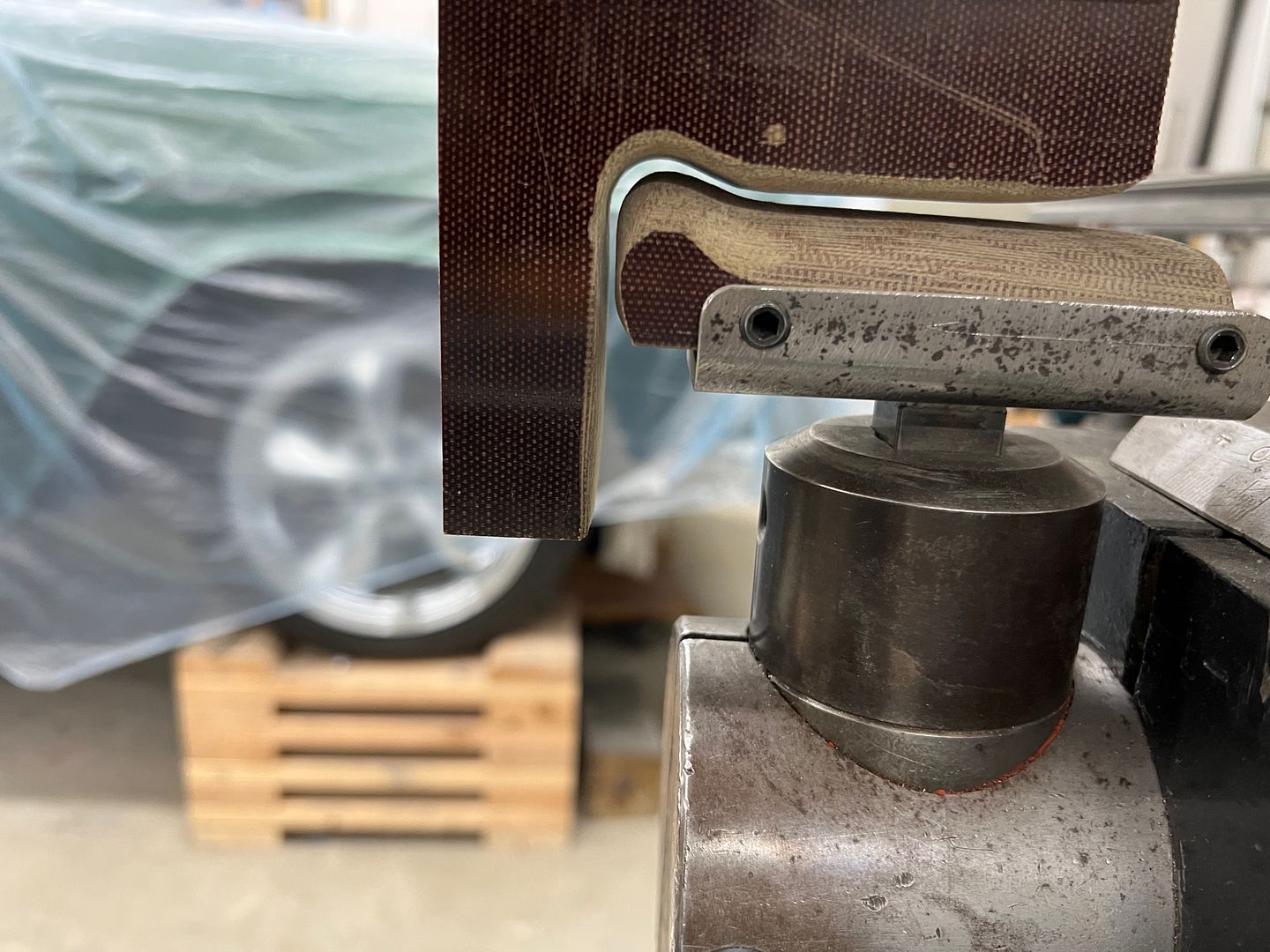
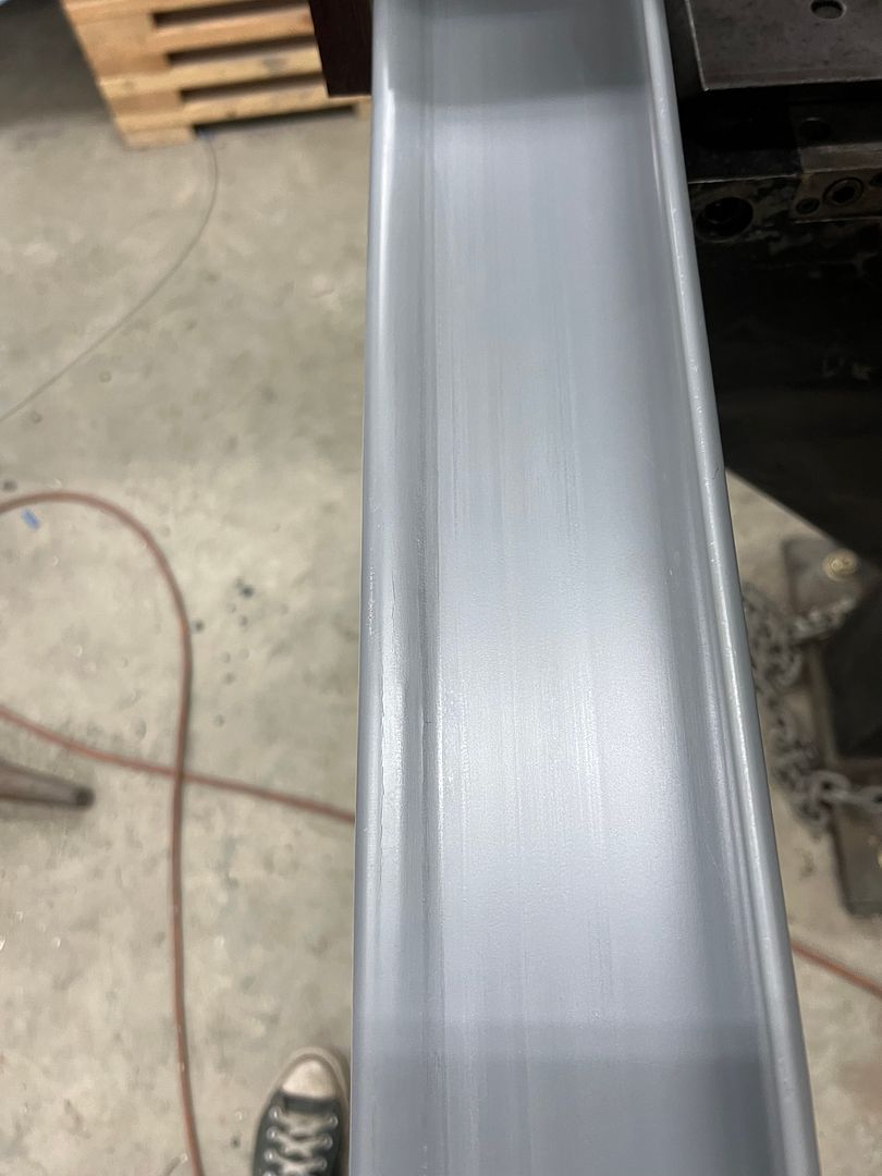
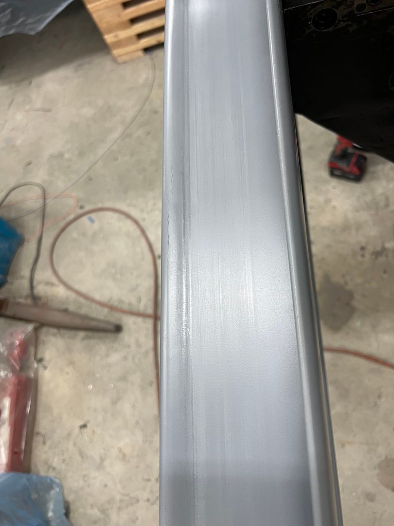
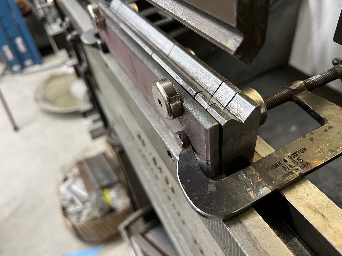
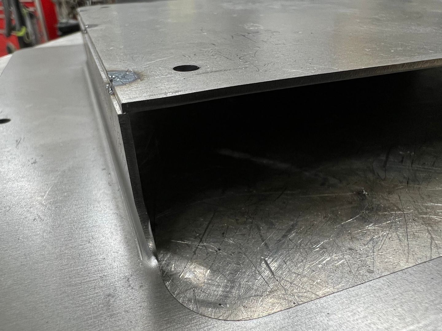
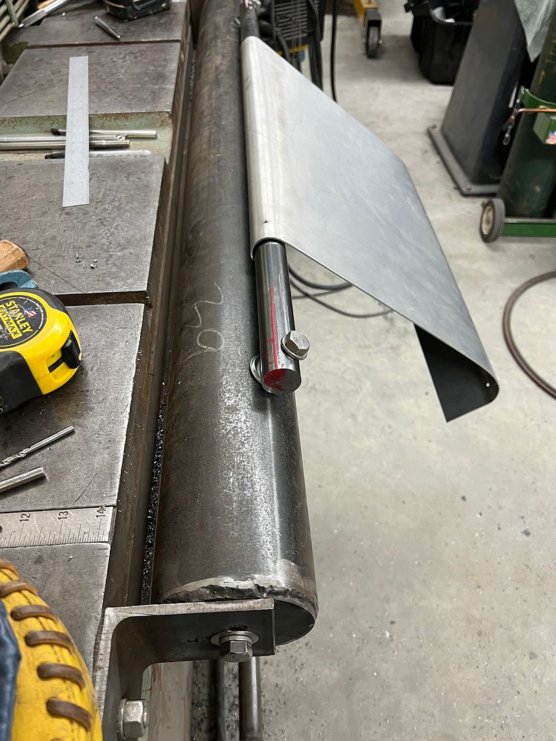
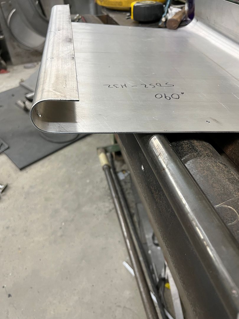
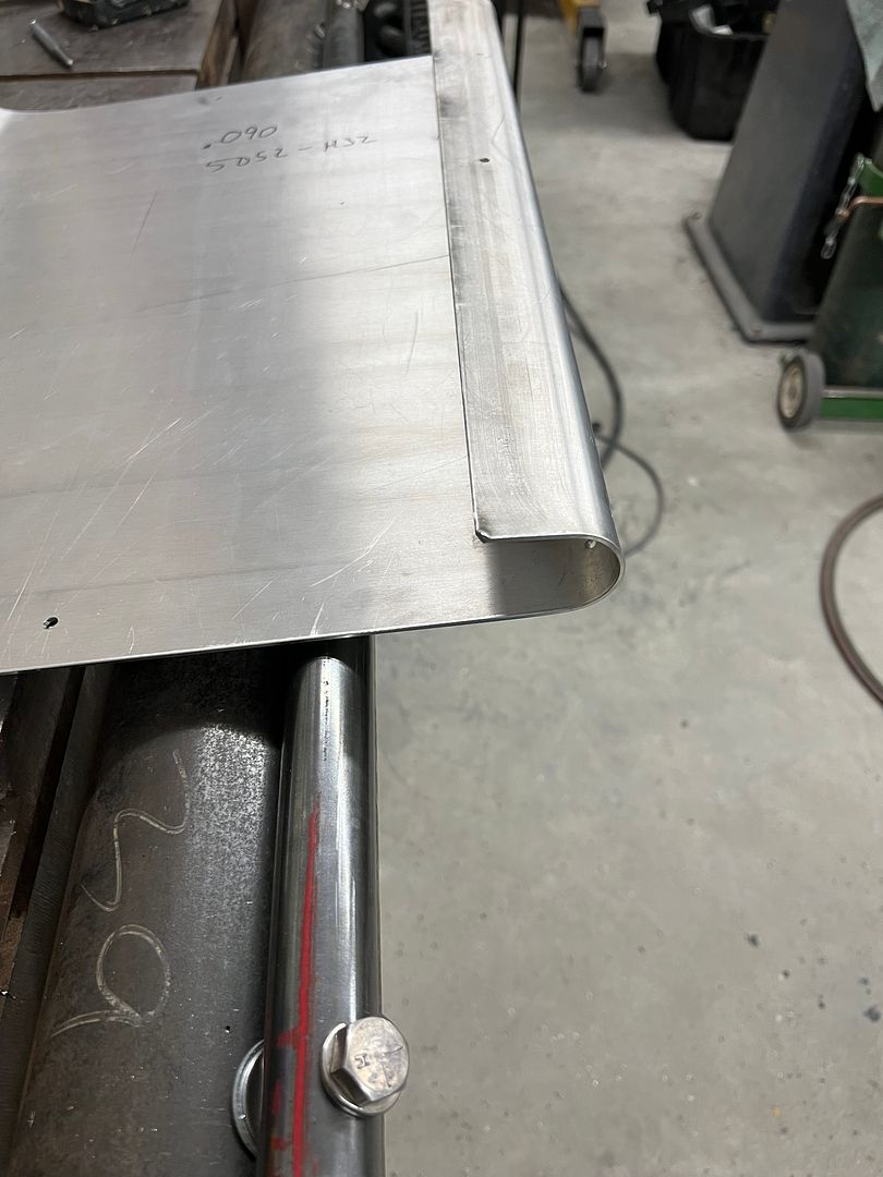
In the tooling department, we needed a tight radius reverse bend on some .090 aluminum, so a Gene Winfield inspired 1-1/4" round stock was added to our 4" pipe. This was bolted straight into tapped holes and used two stacked flat washers to provide the gap. The aluminum was 5052 alloy and was annealed prior to bending.
")