Wagon Progress

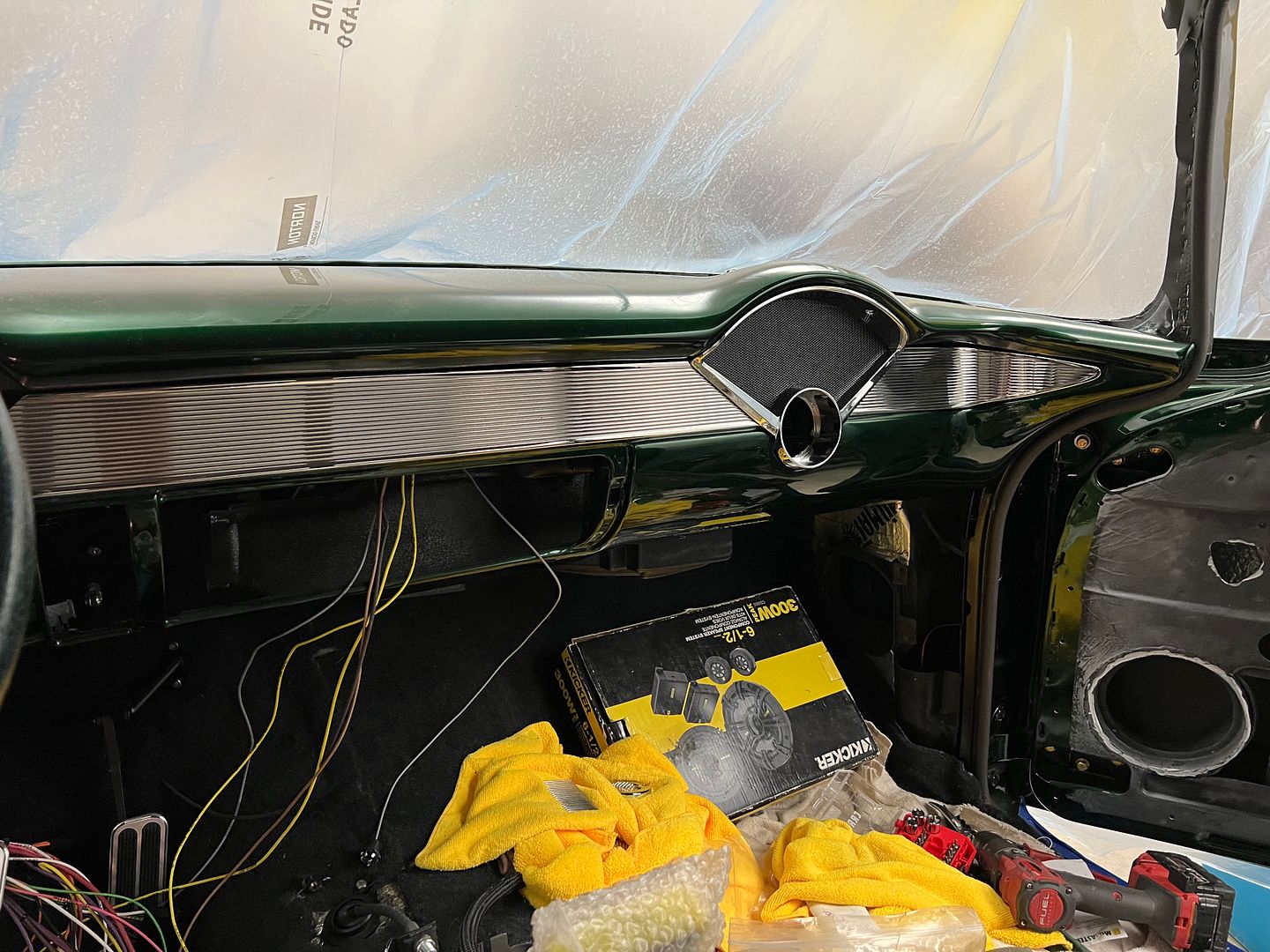
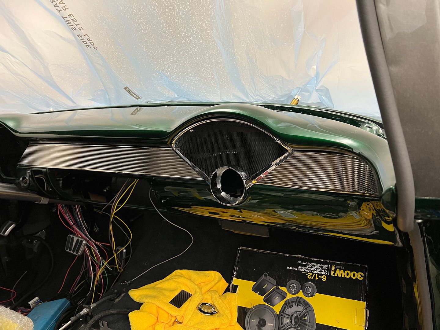
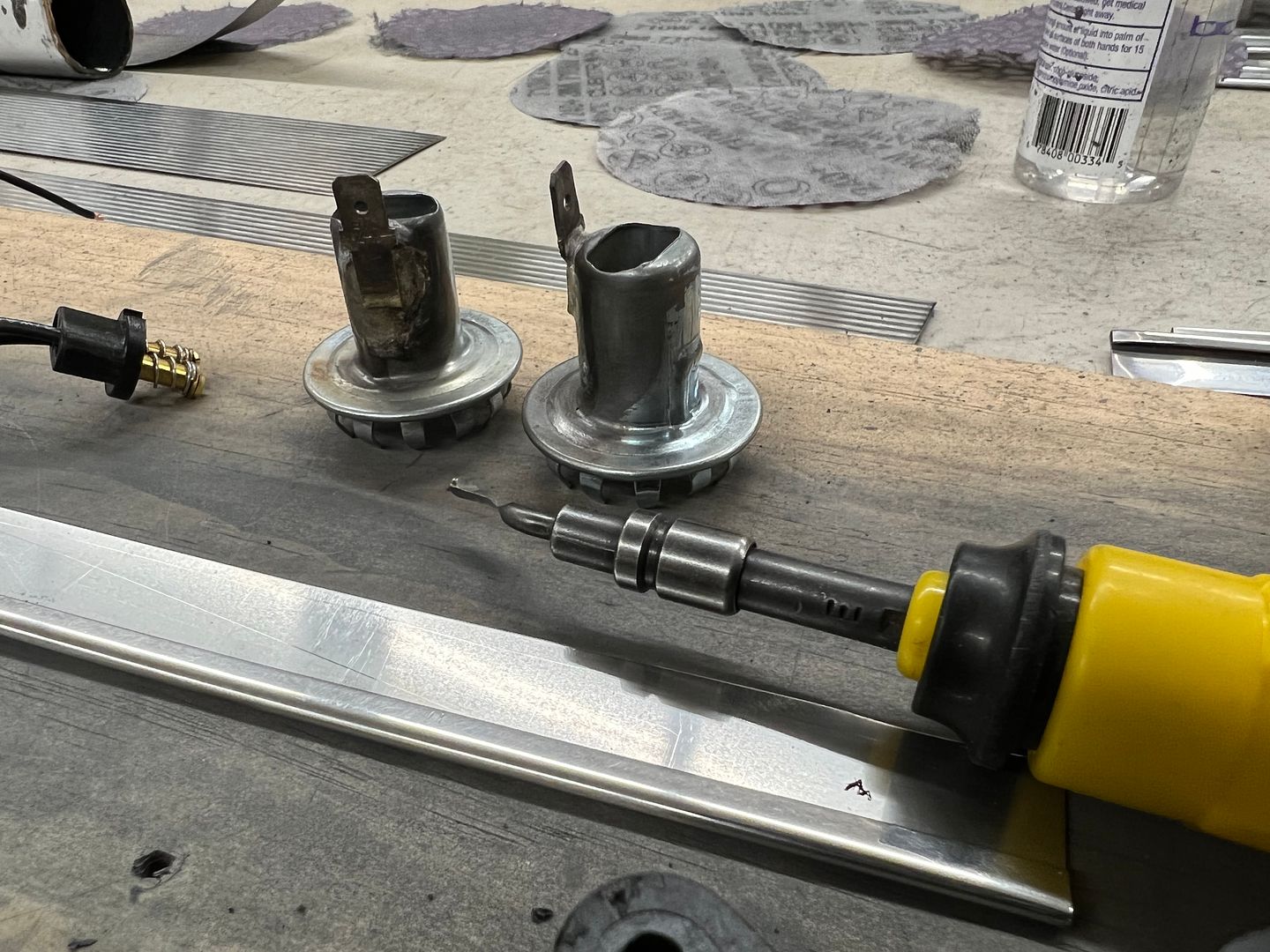
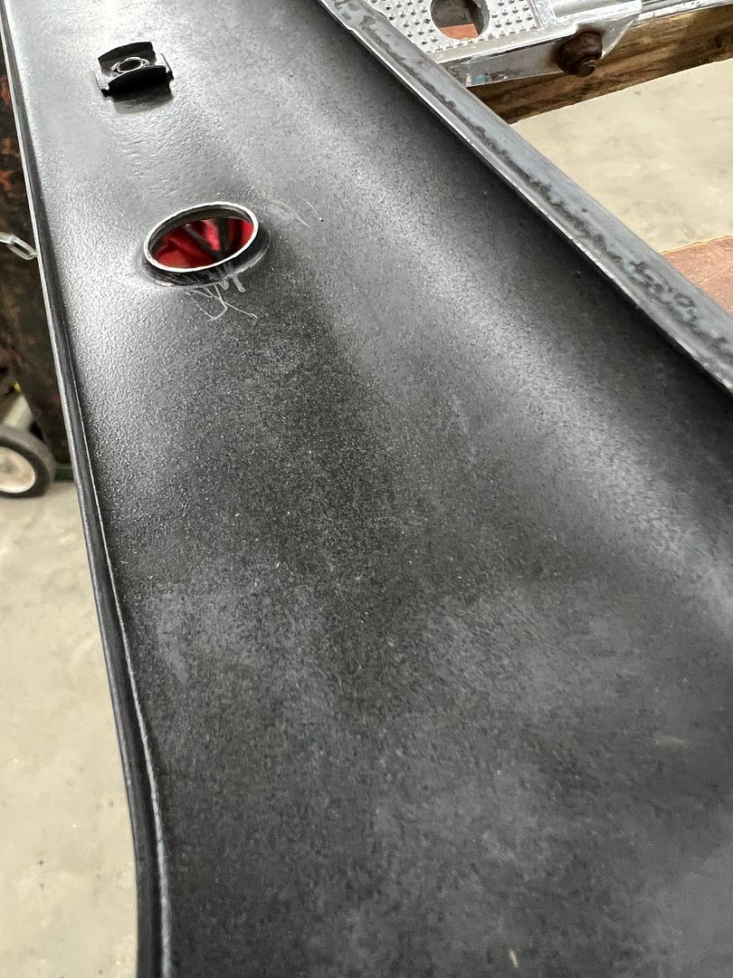
Tying up some loose ends, We still need to finish the wiring at the back of the car, but in the middle of modifying the tail light fixtures for bulb relocation. To that end, in an attempt to keep grounding issues to a minimum, quick disconnect tabs are silver soldered to the tail light housings.


IMG_5356.JPG


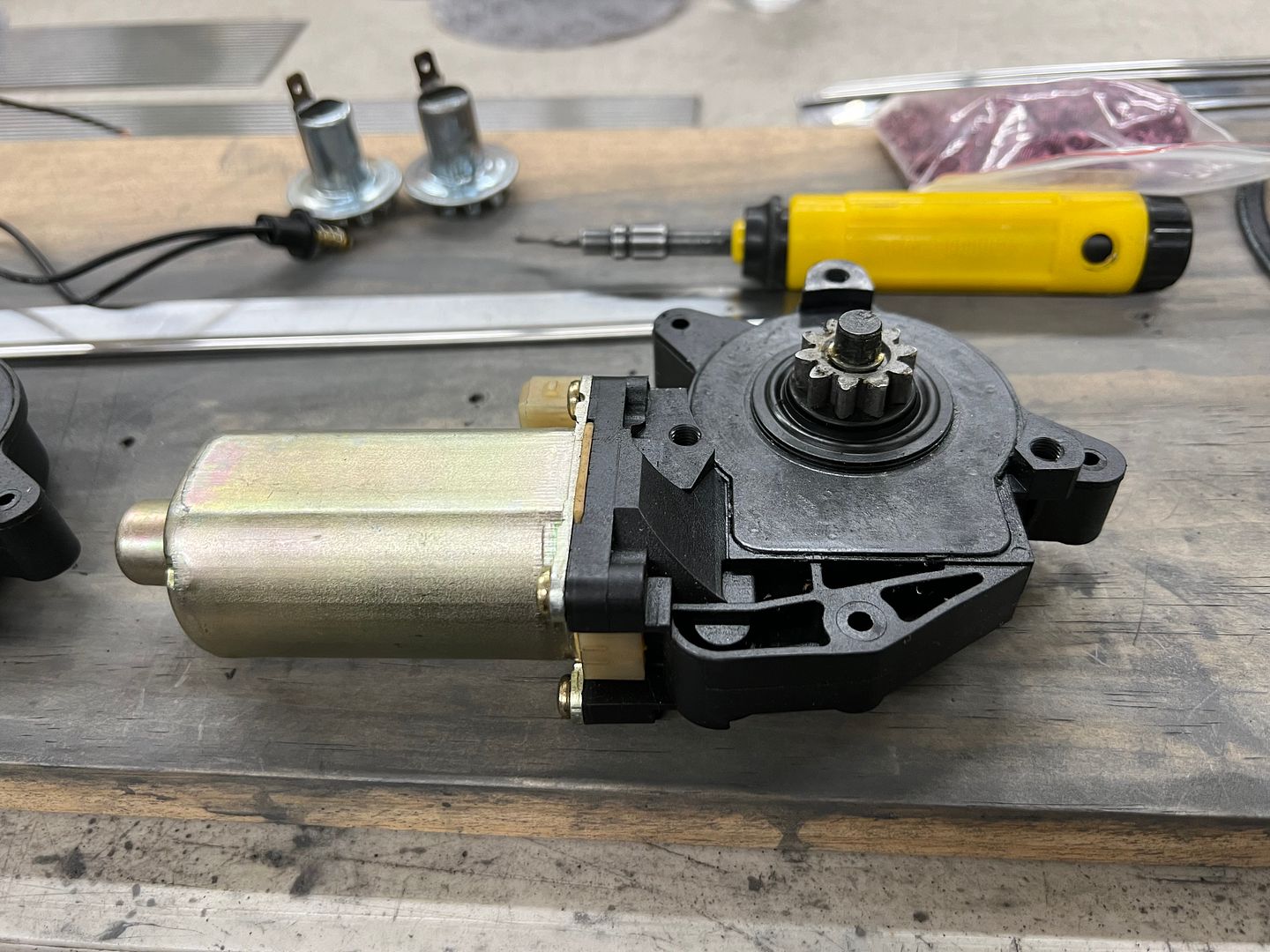
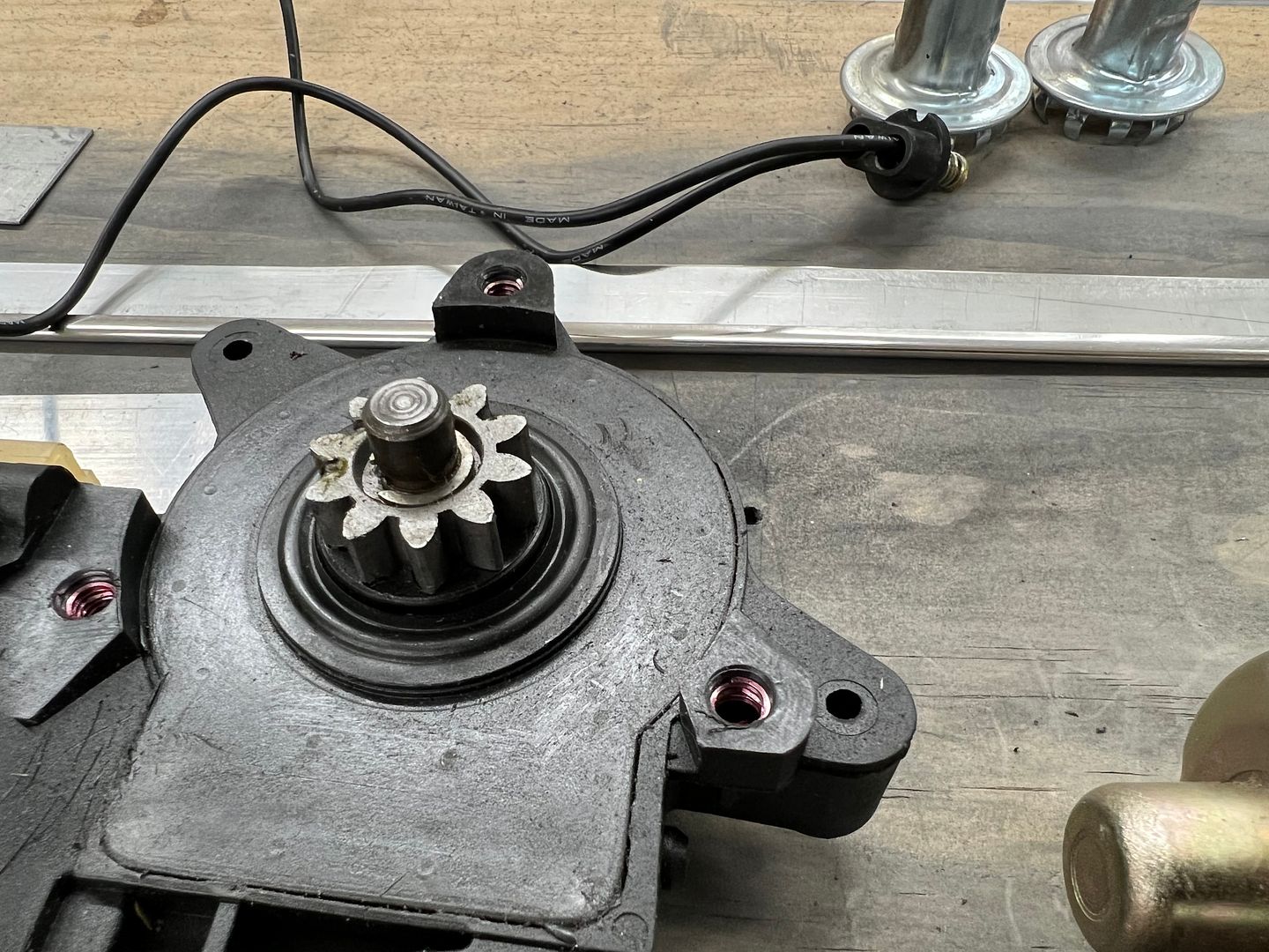
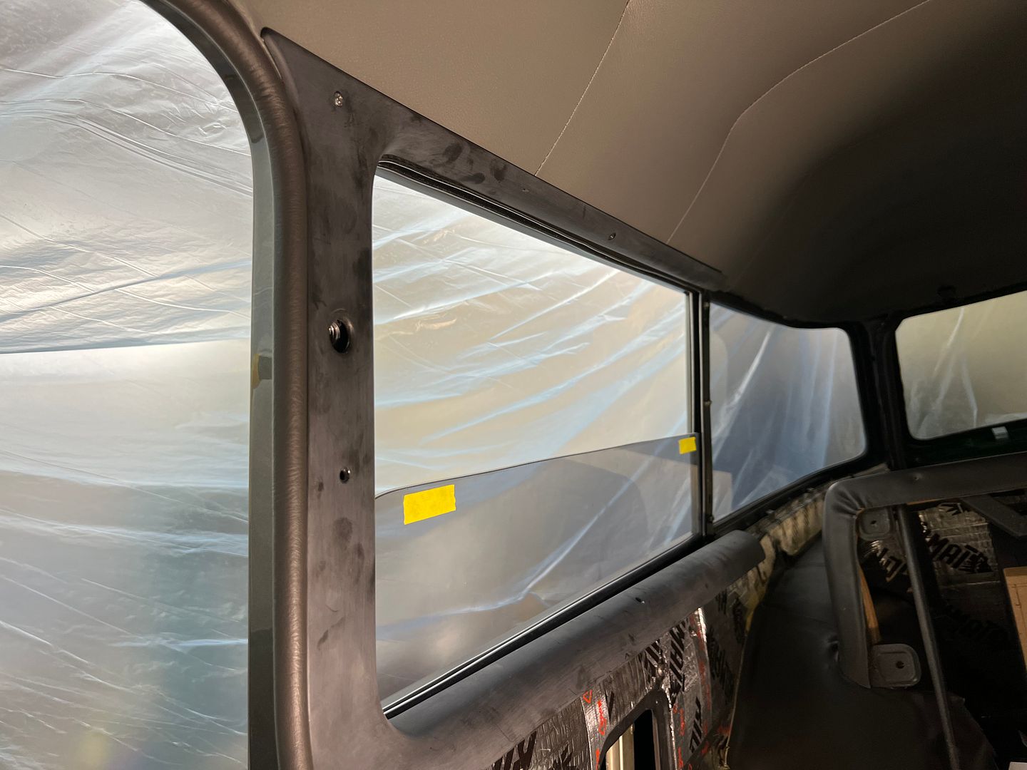
Next, we started the installation of the rear power windows. The rear motors had been mocked up a couple of times and the screw holes in the plastic housings were loose/borderline stripped. So they were drilled and tapped, and 10-32 heli-coils installed for a more permanent solution.


IMG_5354.JPG


IMG_5355.JPG


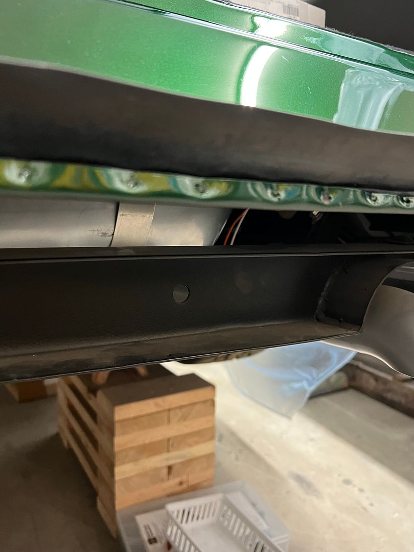
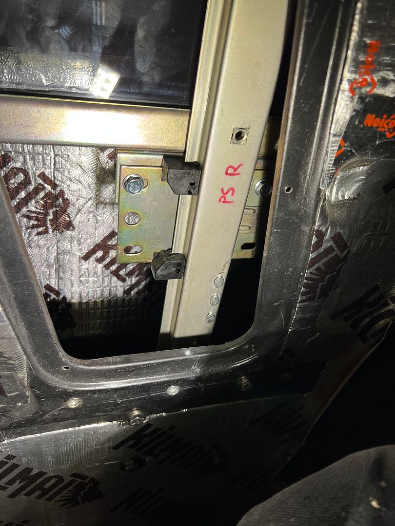
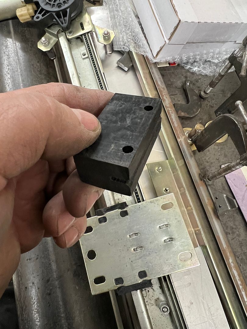
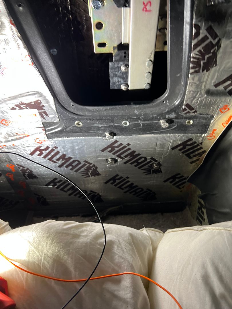
Once the power window track was installed, the OEM stop block for downward travel of the window was found to be useless as the window bottomed out into the wheelwell. Some delrin was cut to size, notched for a snug fit onto the track, and two holes drilled for attachment to the track. Worked well...


IMG_5426.JPG


IMG_5422.JPG


IMG_5429.JPG


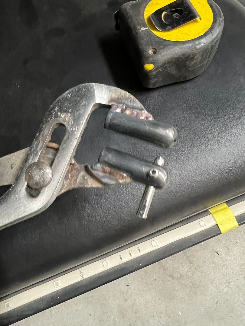
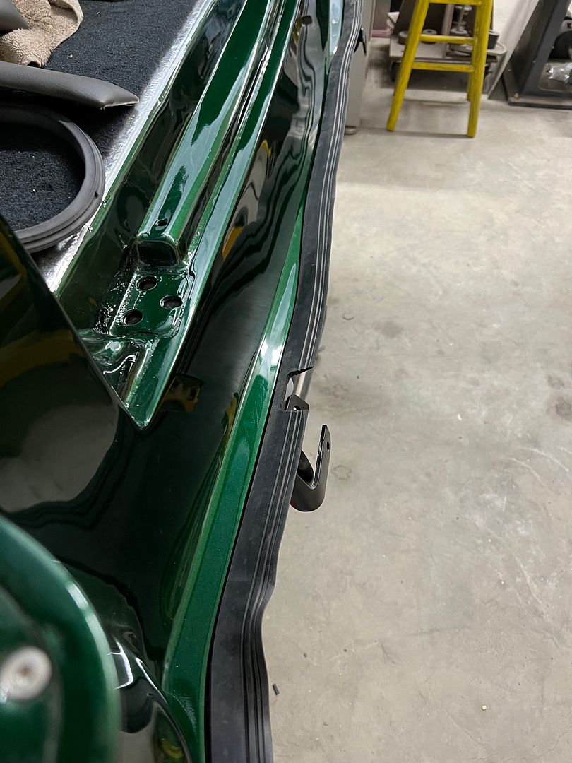
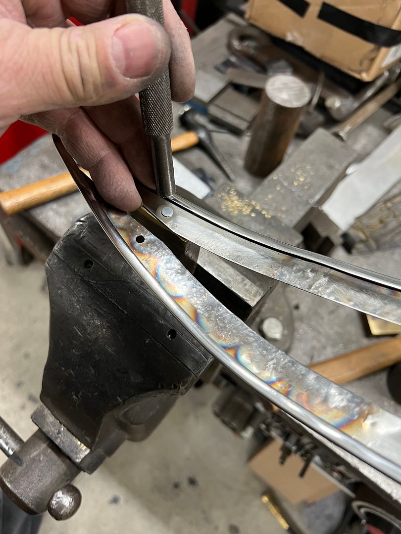
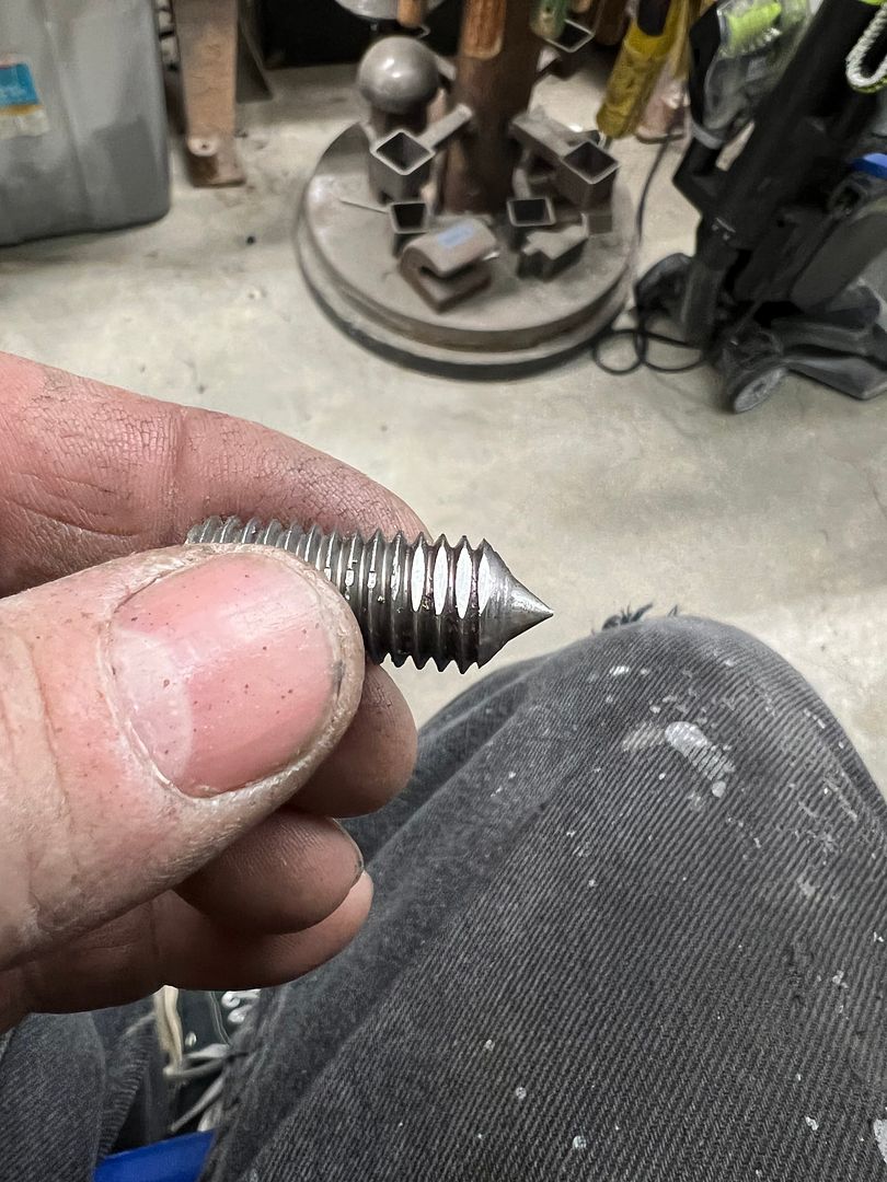
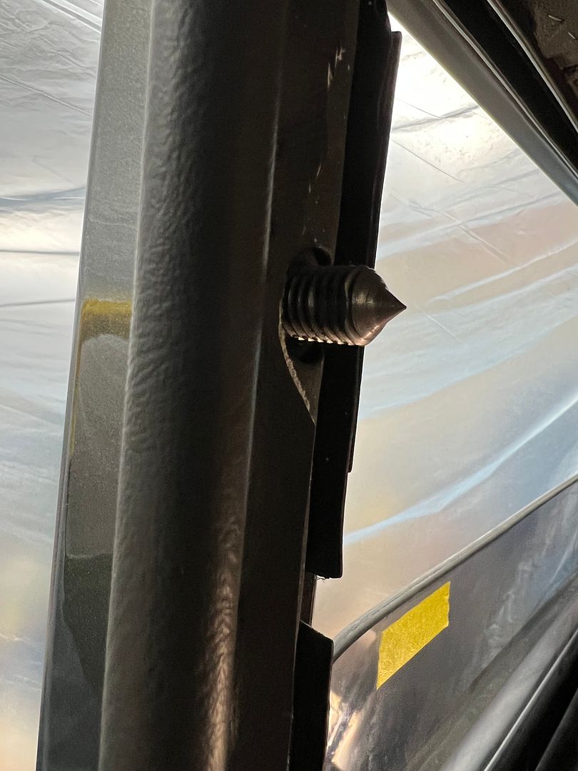
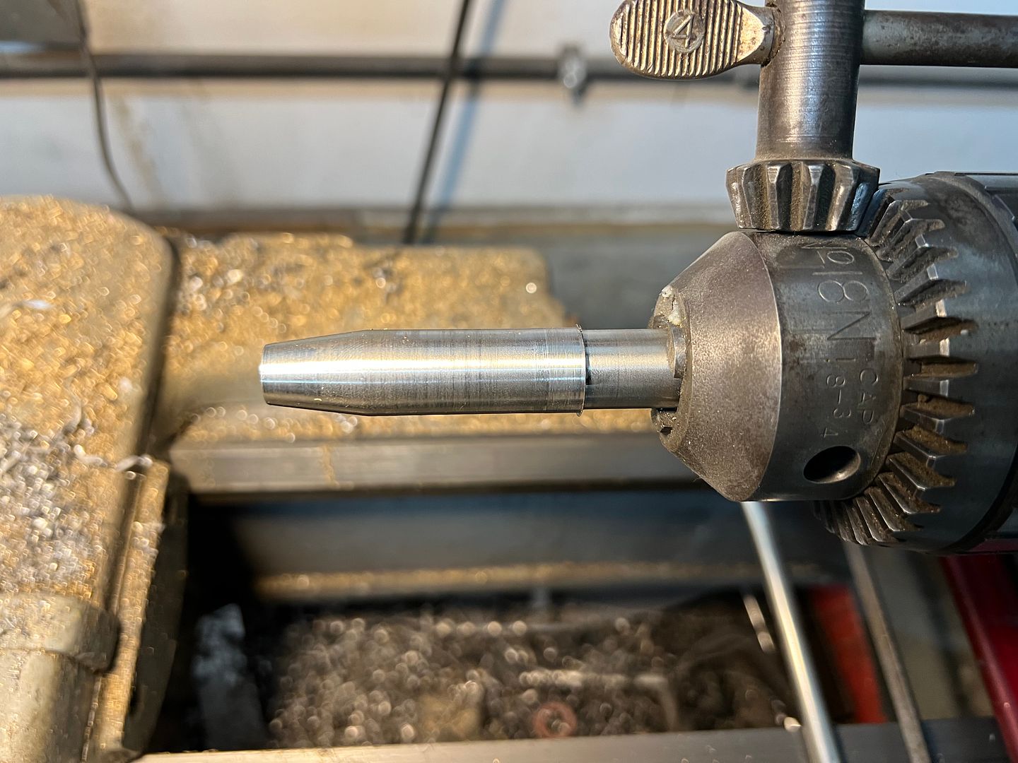
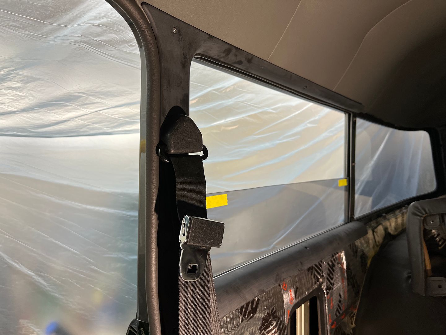
While here at the rear window, we still needed to drill mounting holes for the shoulder harness through the window garnish moldings. A 1/2-13 bolt was used to fabricate a threaded hole spotter on the lathe, complete with flats for wrench installation.


IMG_5435.JPG


IMG_5437.JPG


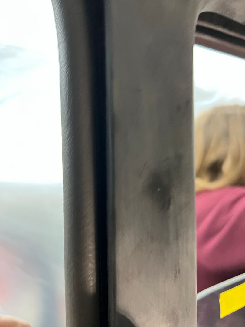
With garnish molding positioned, a quick tap of the dead blow hammer gives an exact location for the hole.


IMG_5439.JPG


IMG_5451.JPG


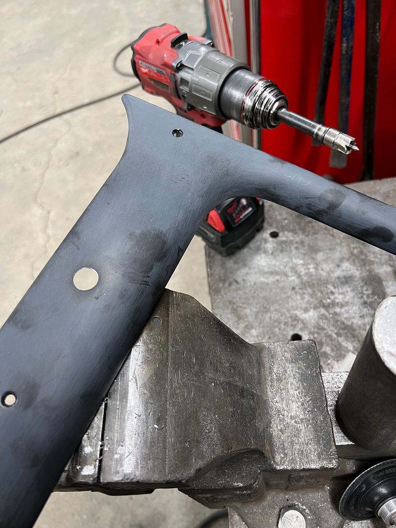
Next, in order that we don't leave an unfinished hole edge, a punch set was machined for the lathe, complete with stepped shoulders to prevent any movement in the jaws when pressure was applied. This will swage the hole edge for a nice inward flange...


IMG_5442.JPG


IMG_5455.JPG


IMG_5458.JPG


IMG_5459.JPG


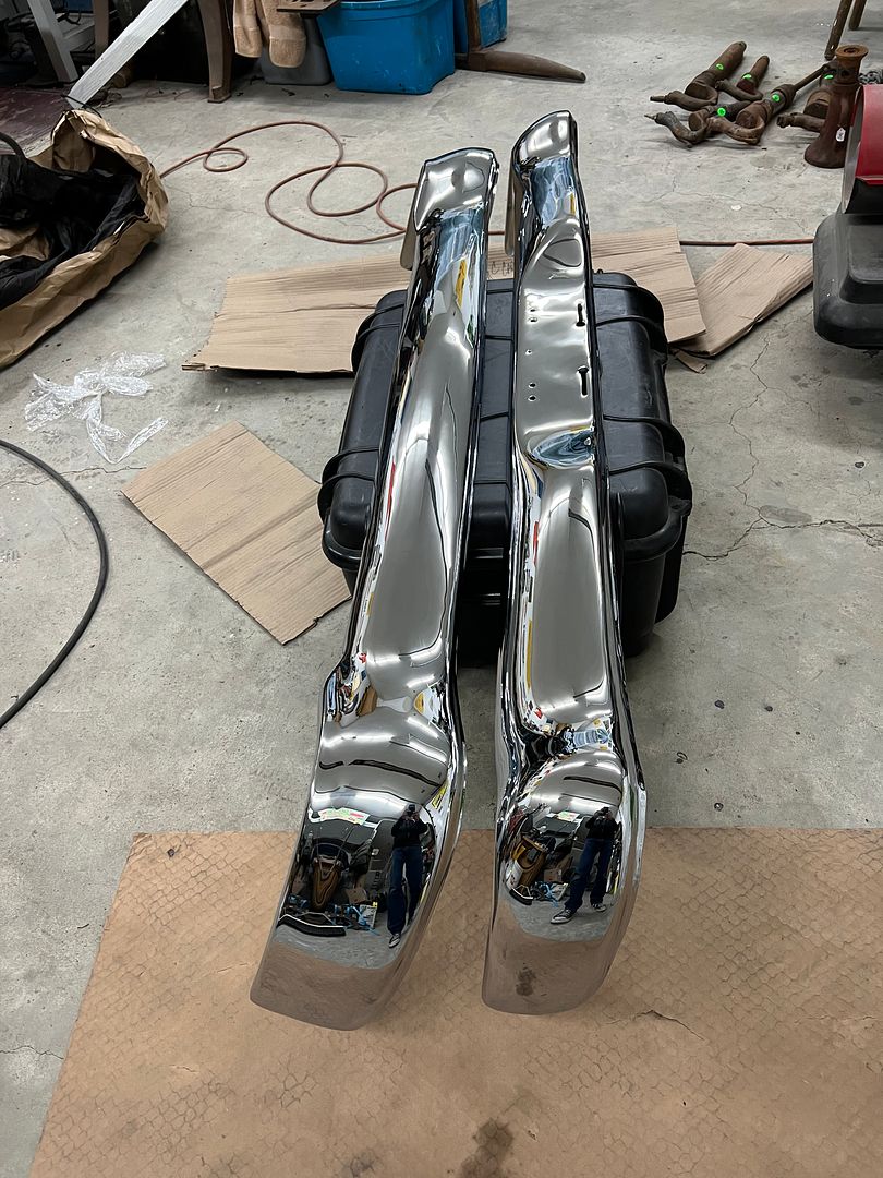
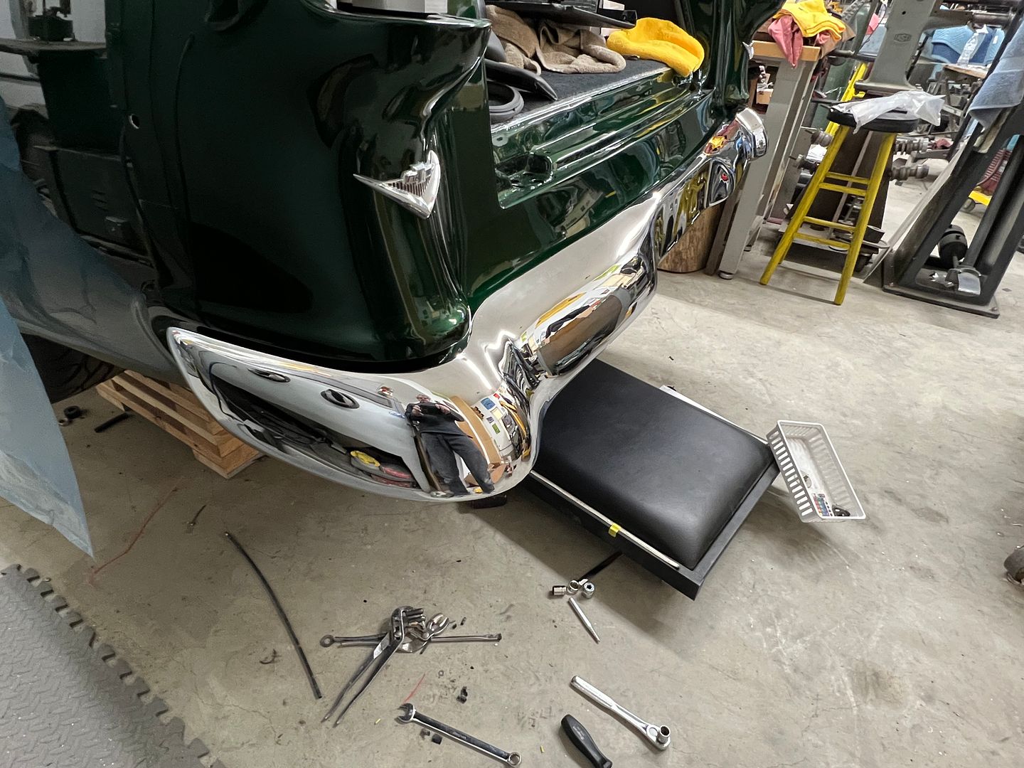
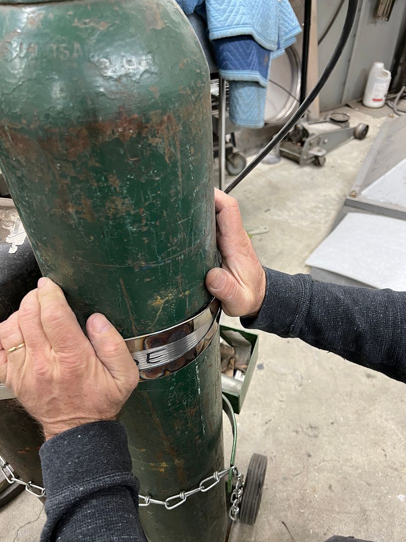
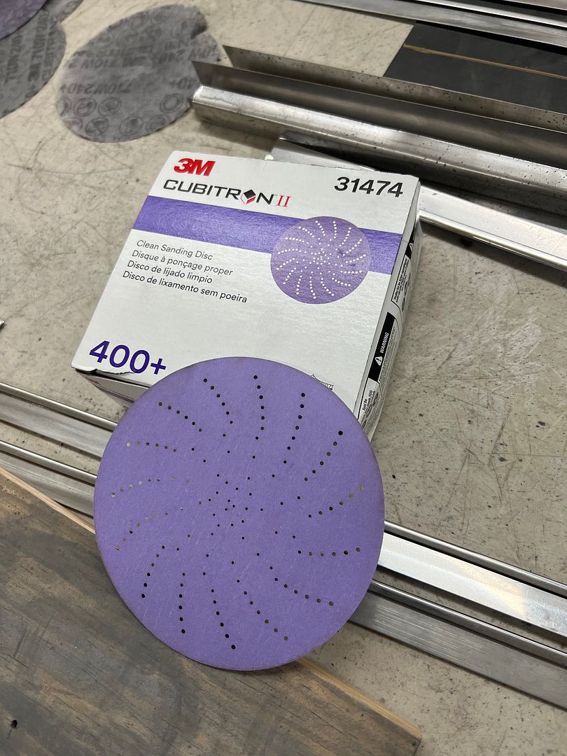
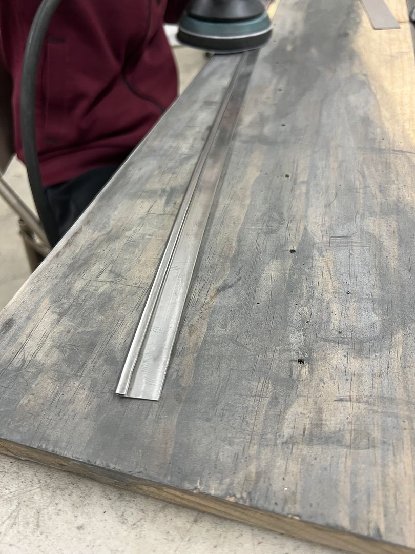
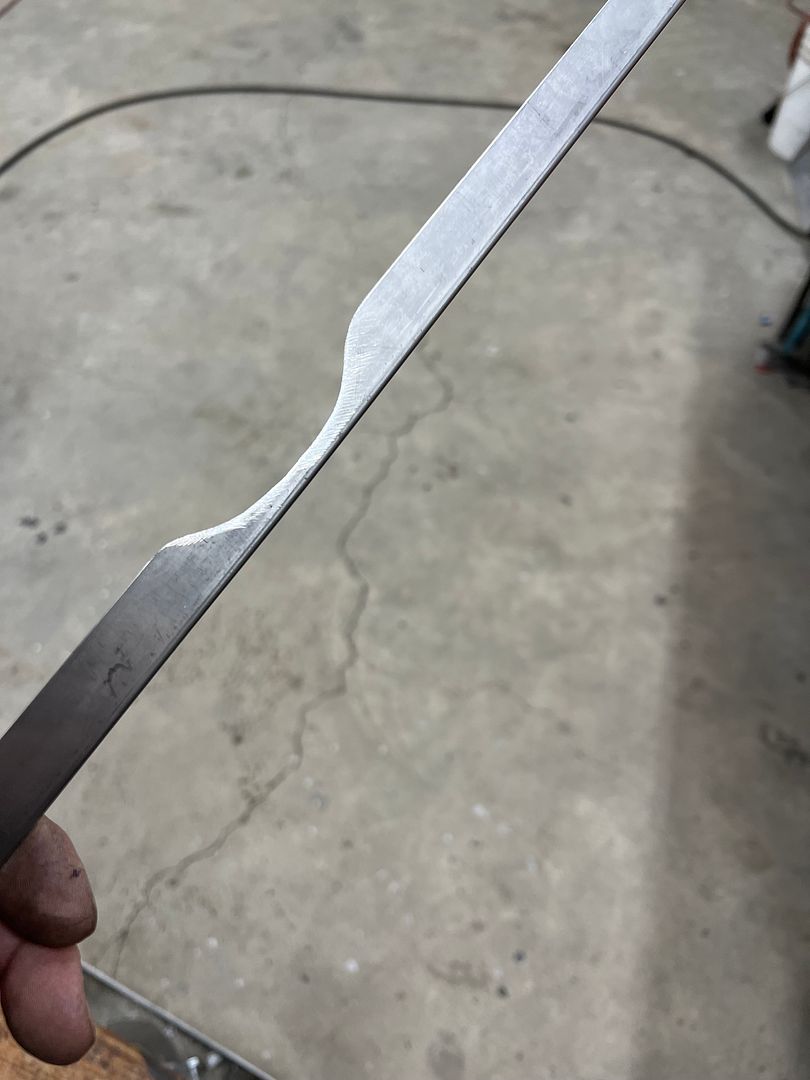
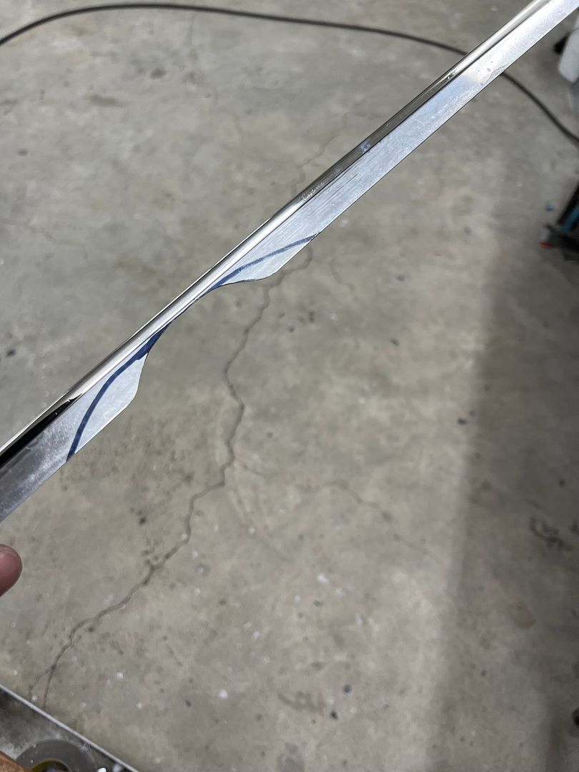
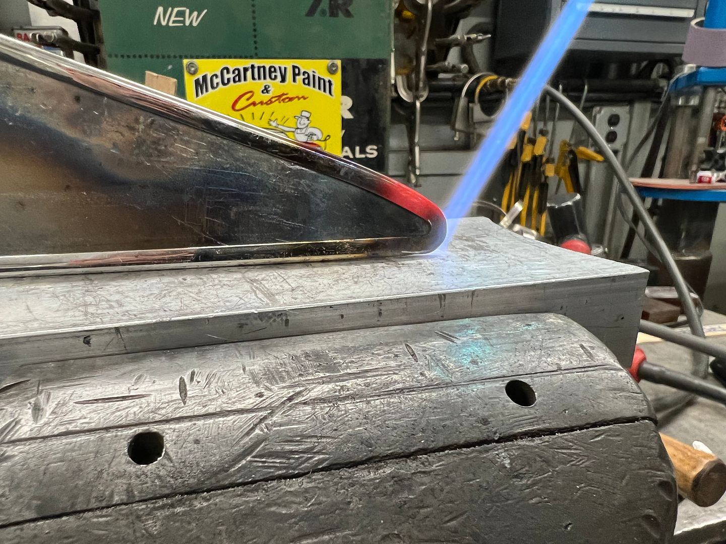
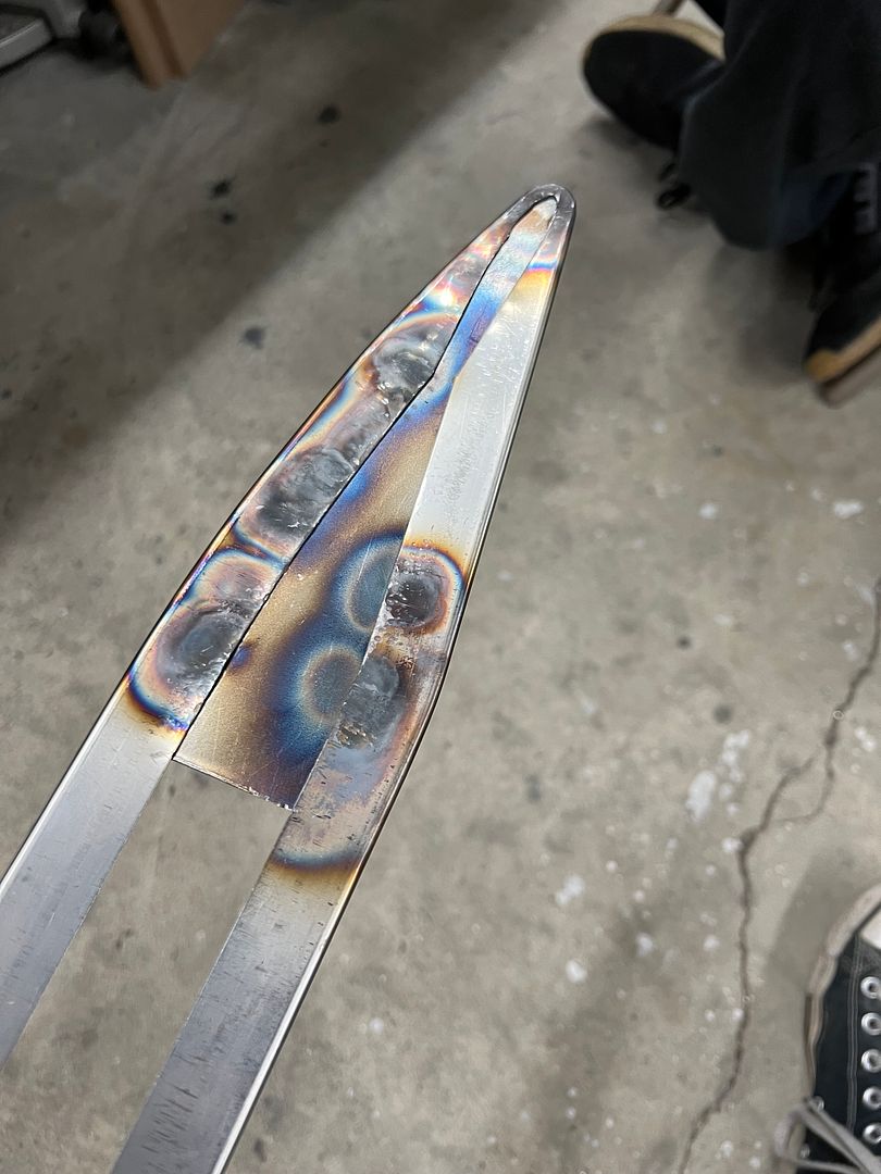
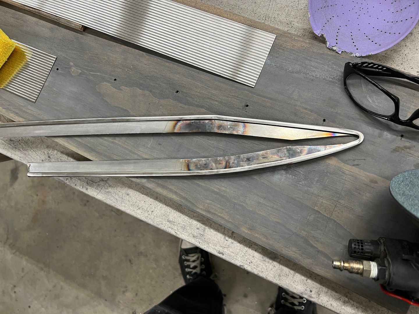
And we had received our new shipment of Cubitron H/L paper from Three Mules Welding Supply for dressing out stainless, so Jared continued prepping our edge trim parts.


IMG_5421.JPG


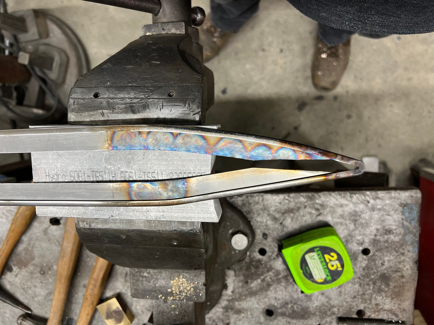
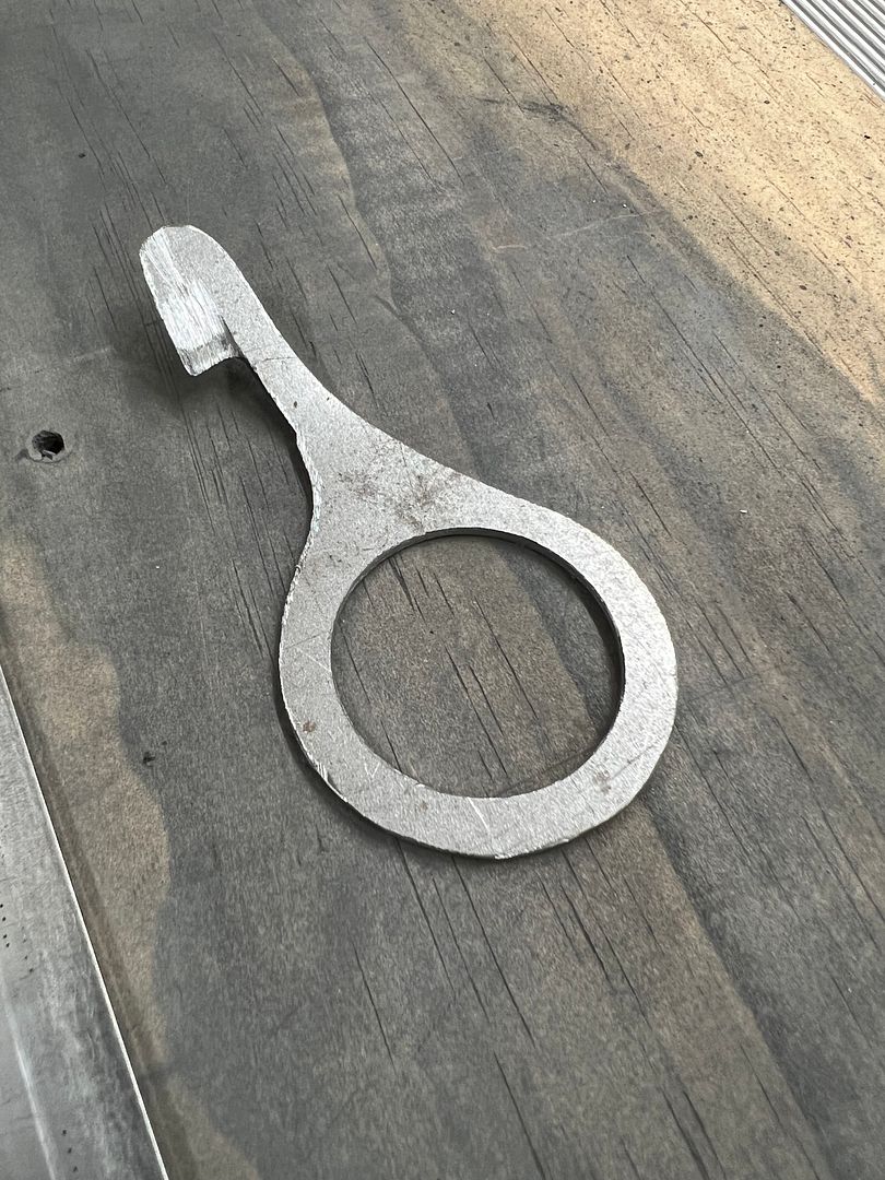
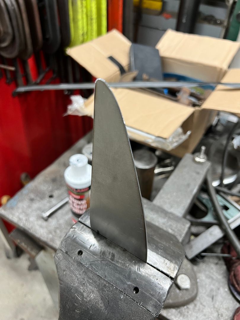
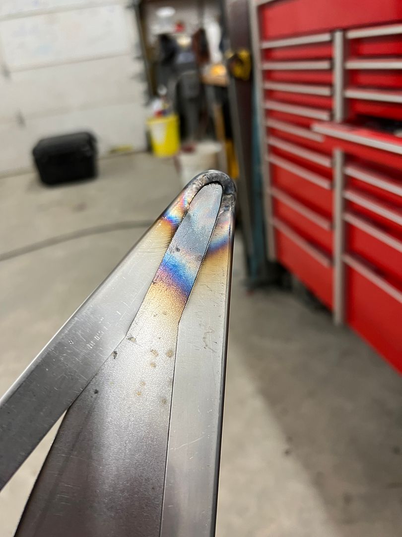
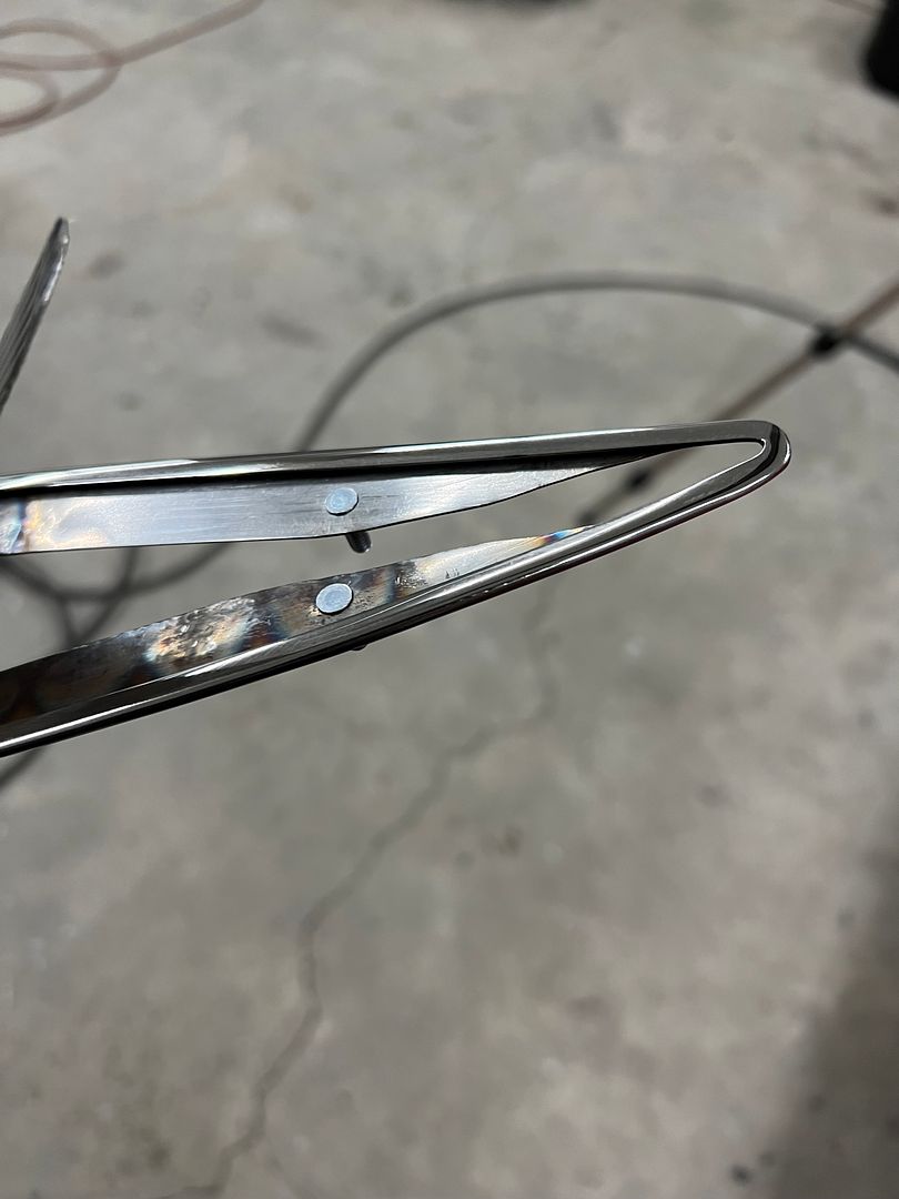
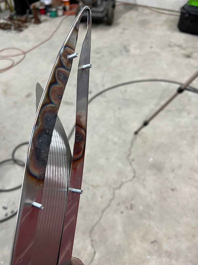
Where the hemming process we used with the bead roller isn't an exacting science, we did have some variance in the gap opening that made the prepping process a challenge. In order to get more consistency in gap width, (and thus flange flatness) a new widget tool was fabricated out of 16 gauge to open up those tight spots.


IMG_5416.JPG


IMG_5417.JPG


.
 
Thanks Pugsy!


More progress on the dash inset. In order to form the outer edge trim to fit, we made an "anvil" out of 19 gauge that match the dash inset. The excess flange was trimmed in the area of the sharp bend.


IMG_5530.JPG


IMG_5531.JPG


IMG_5532.JPG


Some heat was applied to the bend area, slight persuasion added to bend a few degrees, the area flattened to remove any puckers, and repeat.


IMG_5533.JPG


IMG_5545.JPG


Then we needed to shrink the flange on the insides to match the opening. This was accomplished by squeezing the two edge trim ends together, adding a patch of heat to form a tuck, and then flatten out the tucks to provide the shrink.


IMG_5536.JPG


IMG_5538.JPG


For attachment to the dash, 8-32 press studs were installed in the inner flanges where they are also out of sight. The ribbed stainless was installed in the edge trim, then wrapped around our oxygen bottle to provide the radius.


IMG_5555.JPG


IMG_5556.JPG


And a sneak peek at our trim fitted to the dash...


IMG_5558.JPG
 
More shiny stuff...


IMG_5579.JPG


IMG_5582.JPG


IMG_5574.JPG


IMG_5575.JPG


Since I was on a road trip Sunday, I popped in and visited the patent display that we made the hood for. The owner has it re-wired and reflectors installed. This video gives a better idea of what it was used for..


Back in the early 20's there were lights that would attach to the bumper and a cable driven mechanism attached to the front steering so that the light would follow the direction of travel. Advantageous for the limited brightness of the headlamps in those days. So this was likely a salesman's prop for selling such a lighting accessory.
 
Mikey like shiny. The dash panel inserts came out awesome. I take it those bumpers are triple coated? They look outstanding.
 
Yes, copper/Nickel/Chrome. It was quite a few repeated dips of copper and hand filing to straighten out the slight distortion from welding those brackets on the back side.
 
Very nice looking smothies!! NIce work on the dash too. McCartney's in Hiawatha KS? 1956 bumpers? Use to drive through there going to nationals in Topeka.

John
 
Very nice looking smothies!! NIce work on the dash too. McCartney's in Hiawatha KS? 1956 bumpers? Use to drive through there going to nationals in Topeka.

John
Thanks! We’re in Leonardtown MD. Someone mismarked the paper on two counts, actually for a 55, and McCartney Paint and Custom.
 
Last edited:
Before we could install the rear bumper we needed to install the rear bumper seal, this keeps exhaust fumes from sneaking through and getting sucked in the back tailgate. The seal sits in a channel which is then "crimped" with some rounded pliers. Only my rounded pliers did not work, we needed parallel jaw pliers. So these channel locks were modified by adding the round stock. Only that did not hold well enough, so a dimpler was added to the bottom jaw, as shown...


IMG_5624.JPG


IMG_5622.JPG


These dimples gave us enough grip, and any chips were removed and then recoated with a couple coats of epoxy primer.


IMG_5623.JPG


Here's the bumper added, and a video that better shows the hidden hardware...


IMG_5712.JPG


Here's a closer look at the forming of the edge trim for our dash inset trim. We had made a template out of 19 gauge steel to match the dash inset, and used it (and some heat) to form the point. This video shows the shrinking of the flange so the edge trim would match. The upper and lower edge trim was squeezed while applying heat to form a tuck for shrinking the flange and providing the radius.


All shaped, before polishing..


IMG_5696.JPG


Press studs installed...


IMG_5720.JPG


Ribbed stainless insert added and our green radius brake used to match the dash profile...


IMG_5700.JPG


One last touch-up to the polishing and installed in the dash.....


Question regarding the ribbed stainless steel insert. How much smaller should the hole be in comparison to the insert diameter so the ribs will fully bite and hold?........or is the hole the same size as the ribbed insert?

Also can the ribbed insert be found at McMastercar (sp) ?

Thank you,
 
So the ribbed stainless insert is referring to the shiny sheet stock in the middle. The press studs used were indeed McMaster items, FH-832-8 is the part we used. A number 8 screw is .164 diameter, the stud calls for a .161 hole. The sheet stock used for the edge trim was about 1/2 the thickness needed for adequate stud retention, so we added a couple tack welds each to persuade it to stay.
 
Last edited:
^^^ thank you for the correction of my misinterpretation of parts, and for providing the information of was looking for. Now I understand how you got the stud to stay in a fixed position with the use of a tac weld.

Thanks again,
 
Back
Top