Wagon Progress

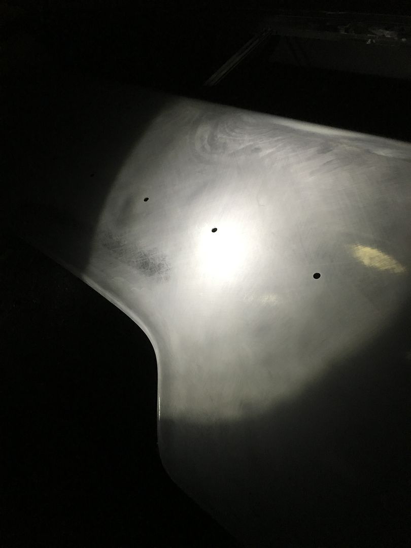
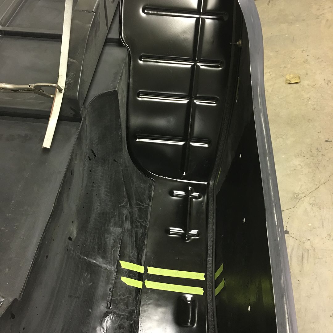
Well after block sanding the latest coat of epoxy....


Picture%204722.jpg


Picture%204743.jpg


Picture%204745.jpg


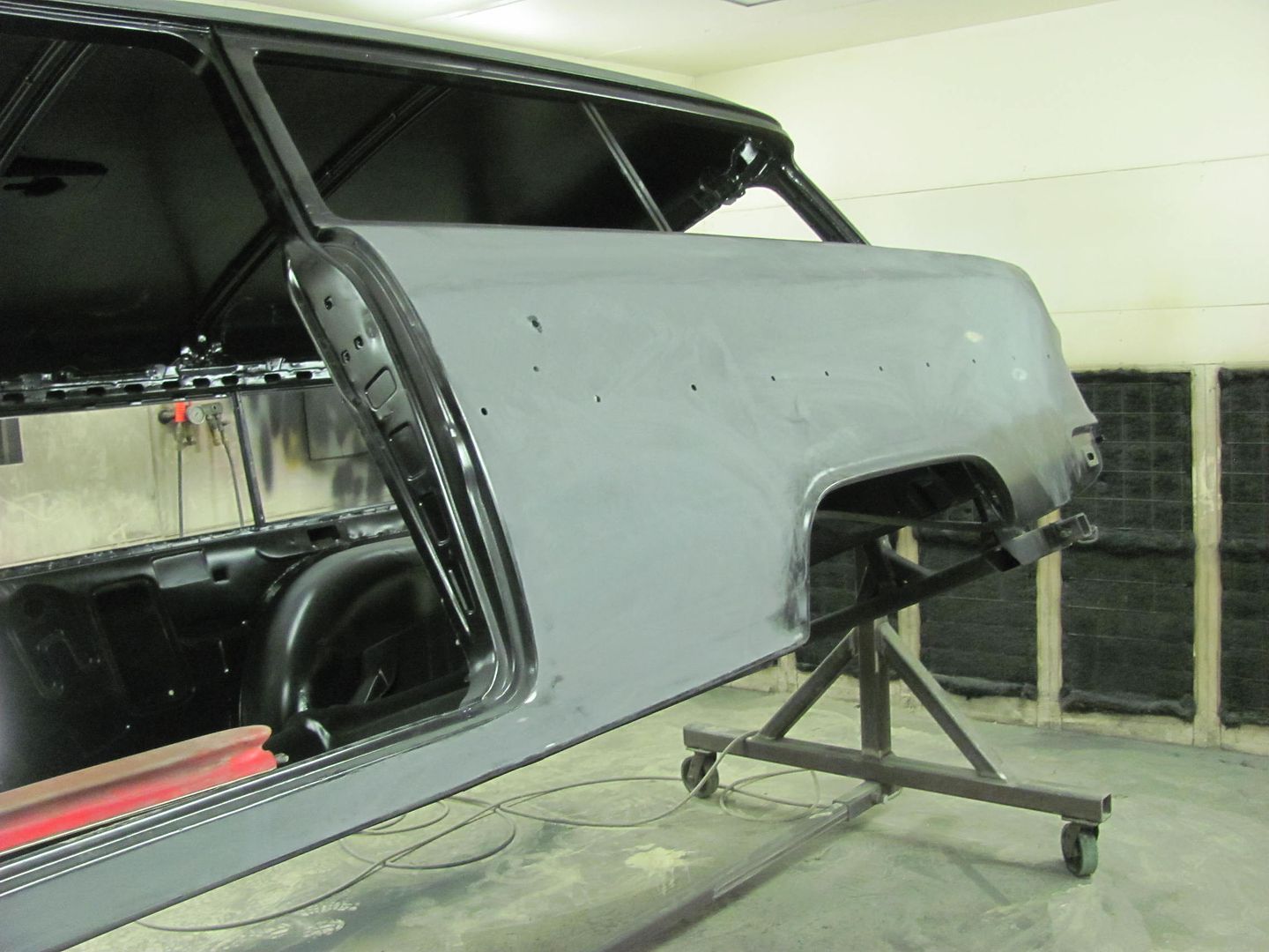
We had a local car show we could attend, but didn't know whether to take the body or the frame...

Picture%204250.jpg


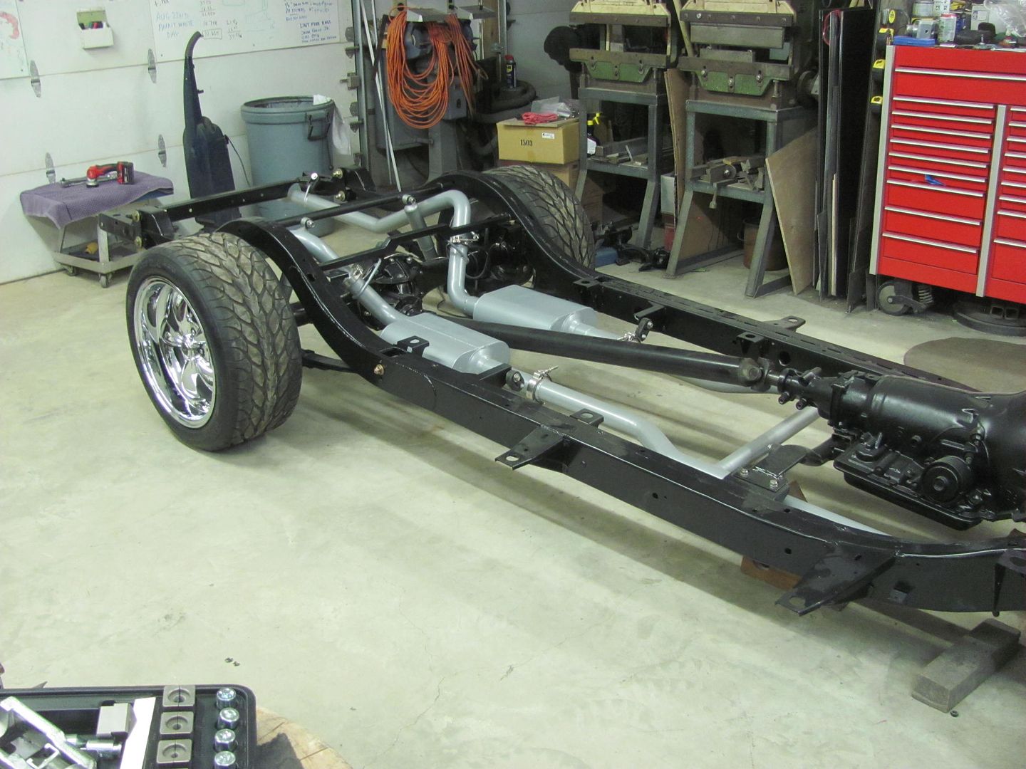
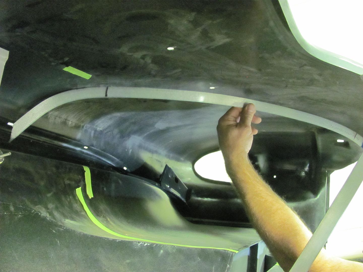
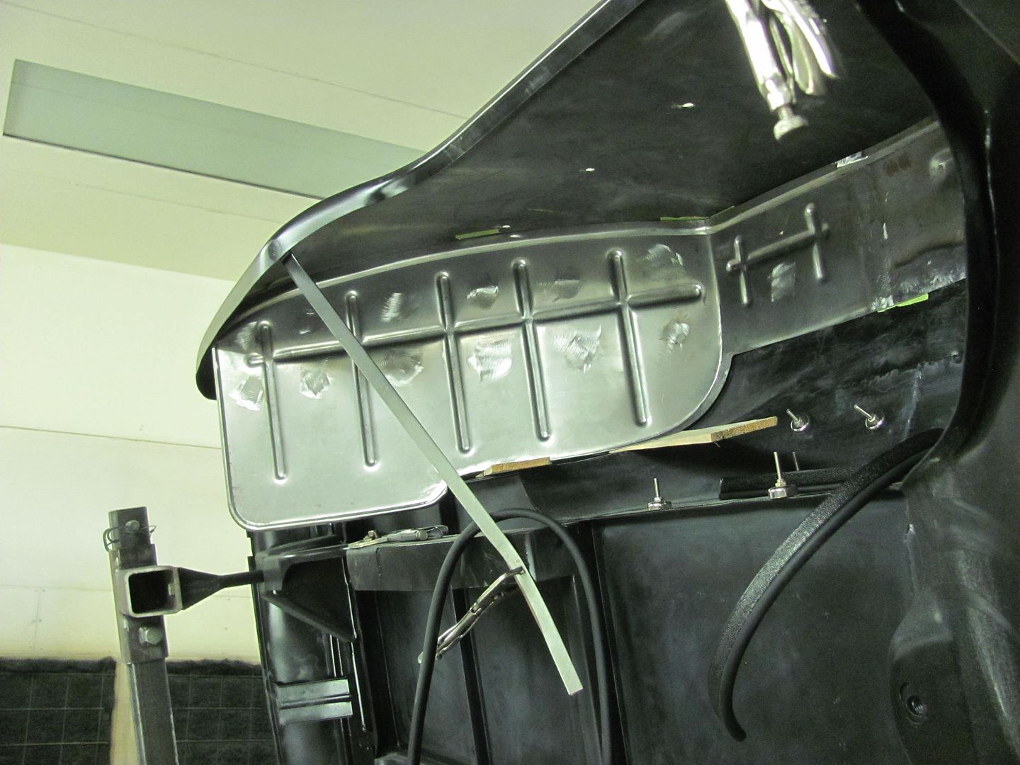
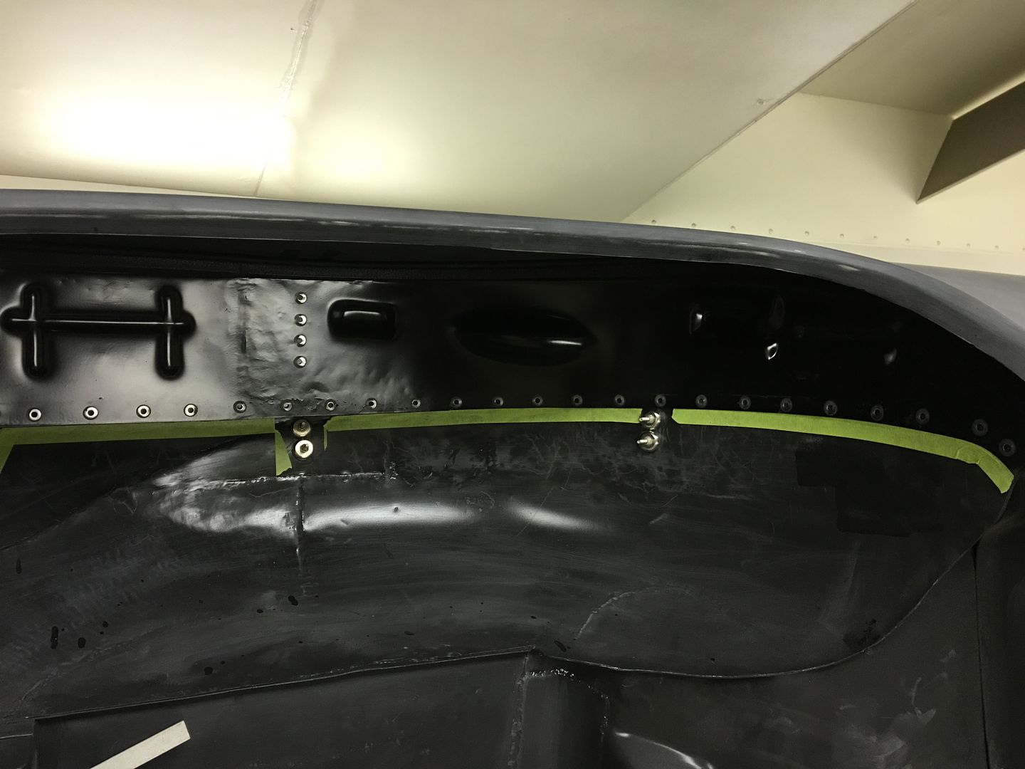
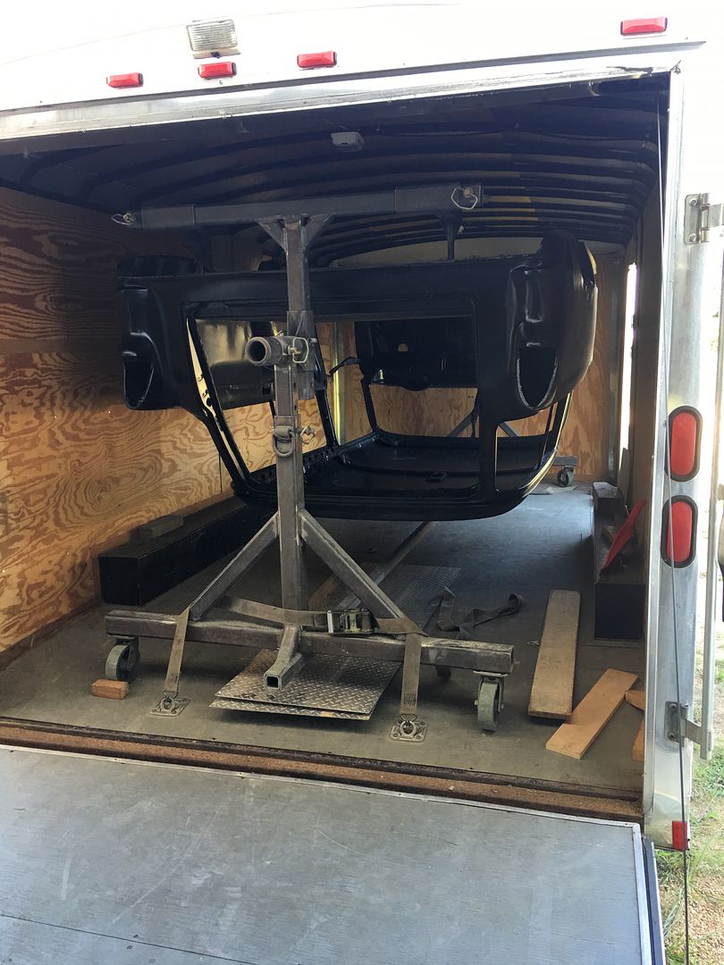
I didn't think the rotisserie would fit in my 16' trailer for some reason, but another measurement proved otherwise. Since it showed more of our metal fabrication, we opted for the body.. All loaded up, height limitations on the ceiling do require inverted travel...

IMG_1562.jpg


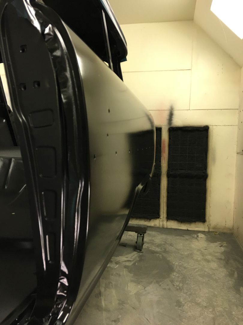
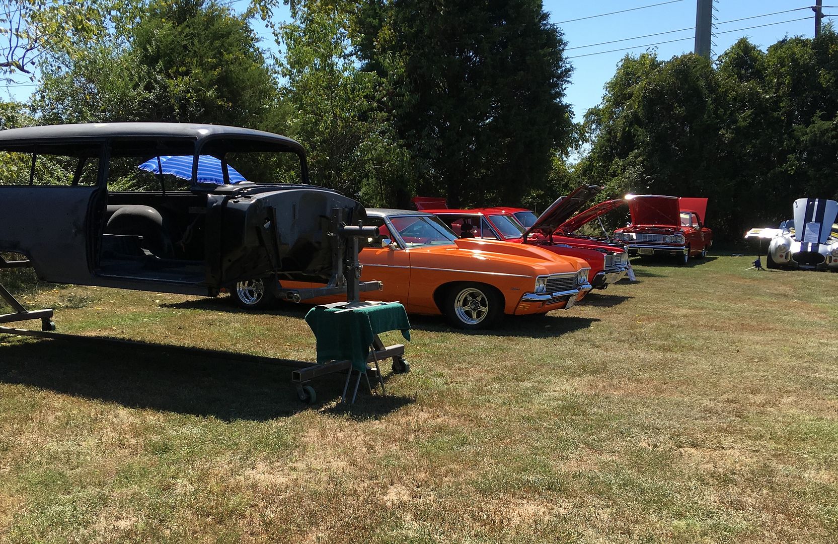
At the show with the "trailer queen"

IMG_1563.jpg
 
Working today on fitting up the wheel wells. The front half is re-popped and uses the same part as the sedans, the rear part is not available. Fitting the front, notice the right lower corner (as shown) tapers up with less overlap for plug/spot welding.


Picture%204793.jpg


The rear section has a notch to clear where the leaf springs used to be attached outside the frame. As the leafs are now suspended inside/under the frame, these notches aren't needed. So we'll make a new set that fills that in...


Picture%204794.jpg


To fix our front repop, a piece of 18 gauge is TIG welded to give us a square corner...


Picture%204804.jpg


Picture%204815.jpg


To make the new piece for the rear, we'll need a method to add beads that cross each other. This will entail a small table to use on the Lennox, an upper punch, and two pieces of matched MDF. Slots will be cut into the MDF, the top used as a guide for the punch, the bottom acts as our bottom die as it "rests" on the table..

The table will be supported in the lower tool holder using a 3/4 shank. The end is turned down to 1/2" to mate into a 1/2" hole in the 4 x 12 table, which is then plug welded.


Picture%204788.jpg


Picture%204789.jpg


Picture%204790.jpg


Picture%204791.jpg


Picture%204792.jpg


For an upper punch, we'll use some 3/4 oil hardening 4140, making it less pointed than the original just in case we want to use it for something besides the 55.


Picture%204801.jpg


Picture%204802.jpg


Picture%204812.jpg


For a bead guide we first need to get a good template of the inside of the quarter. The adjustable spline comes in handy...


Picture%204798.jpg


Picture%204799.jpg


Picture%204800.jpg


MDF is screwed together and then the edge profile cut..


Picture%204803.jpg


Cutting our bead pattern..


Picture%204810.jpg


Picture%204811.jpg


The offset of the original for the quarter seal is added using a tipping die in the Lennox, slight modification on the backstop for the correct width..


Picture%204805.jpg
 
New matches the repop....


Picture%204807.jpg


Picture%204808.jpg


This seal will be used against the inside of the quarter..


Picture%204822.jpg


Running a test pattern... The table height is adjusted to set the punch depth...


Picture%204813.jpg


Picture%204814.jpg


Picture%204816.jpg


Picture%204817.jpg


All clamped up, ready to go. Kyle has already left for the day so we'll finish up next time..


Picture%204820.jpg


Picture%204821.jpg
 
Made our table slightly larger to better hold the panel level for punch depth consistency..


Picture%204823.jpg


More holes for screws added to keep things snug


Picture%204824.jpg


A few holes to fill, we'll get the other side done and weld them all in one sitting.


Picture%204828.jpg


Picture%204825.jpg


Motion picture version:


.
 
Thanks!

Last night we used the poster board template to check the fit of our pattern to the passenger side. Only a slight shave in the middle for a good snug fit. Then we test fit the repop front section of wheel well, which was horrendous. if we were to trim it to fit there wouldn't be enough step flange left over for the seal. So, Kyle added a 1/2" strip of 18 gauge cold rolled to the outside so we will have enough to trim for a proper fit. Still needs to add that corner on this side as well.


https://www.youtube.com/watch?v=DNiSM9Oyp2s


While he was welding away, I trimmed the second panel for the passenger rear wheel well, used the Lennox with the tipping die to add the step flange for the seal, and got it prepped for the bead detail work, which we'll get to on Saturday.
 
Here's a test fit of the reproduction wheel well for the 55, this is the front section. Note the poor fit to the rear side of the quarter panel. I don't know if these are an EXACT reproduction of OEM, but have heard others having similar "gaping hole" issues with their original cars.

This is the driver's side:


Picture%204832.jpg


Picture%204833.jpg


video version....


This is the passenger side we modified Thursday, adding a 1/2" filler strip and then trimming to fit to the quarter panel....


Picture%204831.jpg


.......and shown here with seal in place...


Picture%204835.jpg


Here Kyle is adding the 1/2" filler strip to the driver's side reproduction wheel well.


With the rear section not available in reproduction (blessing in disguise), here is the final layout and trim of our version..


Picture%204836.jpg


Flanges are tipped using the Fasti swaging machine..


Picture%204837.jpg


Test fit of the driver's side wheel wells. The front reproduction piece has the filler strip added but still needs trimming, the rear section is a much better fit than what came out from the factory..


Picture%204838.jpg


Picture%204839.jpg


Picture%204840.jpg


Picture%204844.jpg


Video version:


Once the front section has been trimmed for proper fit, we will butt weld the front and rear section together to eliminate another overlap rust trap.
 
Finishing up on our drivers side wheel well today. The front "modified" reproduction is trimmed and fitted. A light is put behind it to check for gaps...


Picture%204848.jpg


The baffle that sits above the wheel well is made differently as well, this time using a piece of 16 ga cold rolled steel, and trimmed to fill the void. We left a slight gap that we plan on sealing with seam sealer.


Picture%204851.jpg


Shown here with bulb seal against the quarter....


Picture%204850.jpg


The trouble with the factory version of sealing above the baffle is that the expanding foam encapsulates the surrounding area, to include surrounding the slot for trim hardware. It is here that water intrudes, and is held against the quarter causing rust.


Picture%204853.jpg


Our version will leave this hole unobstructed so that any water intrusion that may occur will pass on through.


Now to fill in our screw holes that held together the "MDF Sandwich" that we used for beading the panel. A piece of 1/4" thick X 1" copper flat bar is used as a backer, I find it leaves the back side of the weld much cleaner than using flattened copper pipe.


Picture%204855.jpg


Picture%204856.jpg


Video version:


Picture%204857.jpg


With the front and rear sections having been fitted and trimmed for a butt weld, next we tack the panels together with the TIG..


Picture%204858.jpg


Picture%204859.jpg


Picture%204860.jpg


Now we have a one piece wheel well, no overlap joints to trap moisture and start rust, as the originals had done.


Picture%204861.jpg


Picture%204862.jpg


One piece wheel well test fitted using the bulb seal....


Moving on to the passenger side, both front and back are trimmed and test fitted. Some minor tweaks and we will be ready to trim for a butt weld and TIG these together next time..


Picture%204863.jpg


Picture%204864.jpg
 
Progress from this past week.. Kyle got started on media blasting the drivers side wheel well and I "assembled" the two components for the passenger side..


Picture%204869.jpg


Picture%204876.jpg


Picture%204877.jpg


We plan on epoxy primer on these prior to installation, so the media blasted surface will give a good bite for the primer.

Here's the test fit of the assembled passenger side wheel well...


Picture%204878.jpg


Picture%204879.jpg


Next, the road trip on Friday.. To preface, a couple weeks ago someone had posted a link showing a Baileigh English wheel on eBay (the big one). In the background was one of the Baileigh power hammers. So I called the contact number in the ad, asked if the hammer was available, which he said yes. He gave me a price, asked for a deposit, and this past Friday was the pick up day. I left the house at 1:45 am, picked up my nephew Chris, and drove to CT. Got it loaded up, made it back to the house by 10 pm, quite a long day. Wait....it's supposed to rain tomorrow, let's unload! So we got it off the trailer and inside by 11. Saturday, after sleeping in, was spent locating a spot for the machine, hooking up power, and trying it out on some scrap metal..


Picture%204882.jpg


Excited to have this additional capability in the shop.
 
And I thought my little kent white air power hammer was cool!
Nice purchase, but now you have to find the time to become proficient on it.

Looks like lots of space for dies, did any come with it?
 
It came with planishing, shrinking, and linear stretch dies.. but yes, plenty of storage room for buying more.. That's marketing strategy there...
 
Was working on finishing blocking roof and quarters Saturday when the high winds took out the power for a couple hours.. Not to be deterred, the Milwaukee flashlight comes to the rescue...


Picture%204886.jpg


Power came back on just after lunch and we got the next dose of Epoxy applied. These sure are some long quarters, I think I'll try a Yugo for the next project, shouldn't need anywhere near the paint prep...


Picture%204883.jpg


Picture%204885.jpg


or the video version:


.
 
This is the first sprayout sample... we'll view these again tomorrow in the sunlight to see the true colors...

Chrysler pewter over H/K organic green.


Here's our paint sample with some sunlight added. The incremental lines to make the radius really show up, but quite a bit of pop in the sunlight..

 
Started the evening off with some TIG practice, here tacking two panels together....


Next, to use our fancy dancy paint rollers, getting epoxy inside the rocker panels and inner quarter in prep for installing the wheel wells... Had some SPI epoxy mixed up, poured a small amount in the inner quarter and used the long narrow roller to push paint all the way to the front of the rocker. Lather, rinse, repeat.

Picture%204775.jpg


Picture%204779.jpg


Picture%204781.jpg


IMG_1942.jpg


...and used a brush to cover the bare metal that was above the quarter panel's baffle..

IMG_1944.jpg


There was a bit of overflow, or dust control shall we say.

IMG_1945.jpg


One rocker down, one to go..
 
With the rockers and inner quarters covered with some SPI epoxy primer, tonight we'll get the quarter panel baffles welded in place so we can install the wheel wells.


IMG_1943.jpg


Here's our home-made baffles:


IMG_2009.jpg


Primer cleaned off for the plug weld holes..


IMG_2010.jpg


IMG_2012.jpg


Kyle plug welding:


Now plug welded in, we'll clean up these welds tomorrow evening, epoxy prime and seam seal around the top profile of the baffle inside the window extrusion area.


IMG_2015.jpg


IMG_2016.jpg
 
Amazing craftsmanship! Always enjoy watching and learning from you, thanks!
 
Thanks!

When we fabricated the quarter panel baffles we trimmed the upper profile to leave about a 1/16" gap, so that any possible body flex would be less likely to rub paint..


IMG_2016.jpg


Plus, it gives a good anchor for the seam sealer....


IMG_2026.jpg


Then we used masking tape to mark off the edges of the flange so we could transpose these to the wheel well for drilling plug weld holes...


IMG_2027.jpg


IMG_2029.jpg


IMG_2031.jpg


Next, we have another yellow vehicle to work on. A new driver at a local high school missed seeing the bright yellow oversized vehicle as it passed, and backed into the side of it..


IMG_2022.jpg


New filler panel was made out of 18 gauge steel, ready for some SPI epoxy..


IMG_2025.jpg
 
Fitting up the one piece wheel well into the passenger side quarter. Once fitted, the edge is marked with tape, wheel well removed, and the width available beneath for plug welds is noted. Then holes are punched in the wheel well to match, and it gets refitted. We started at the front so we could use vise grips to clamp, and worked progressively toward the back.


IMG_2073.jpg


IMG_2074.jpg


IMG_2075.jpg


We did have a few plug welds that were contaminated from the epoxy primer, so we'll grind everything smooth, fix those areas, redress the welds and finish any bare areas with epoxy primer. One step closer to the Line-x coating on the underside...


Here we are all tacked in place:


.
 
Back
Top