Wagon Progress

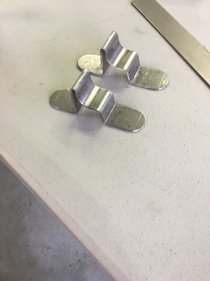
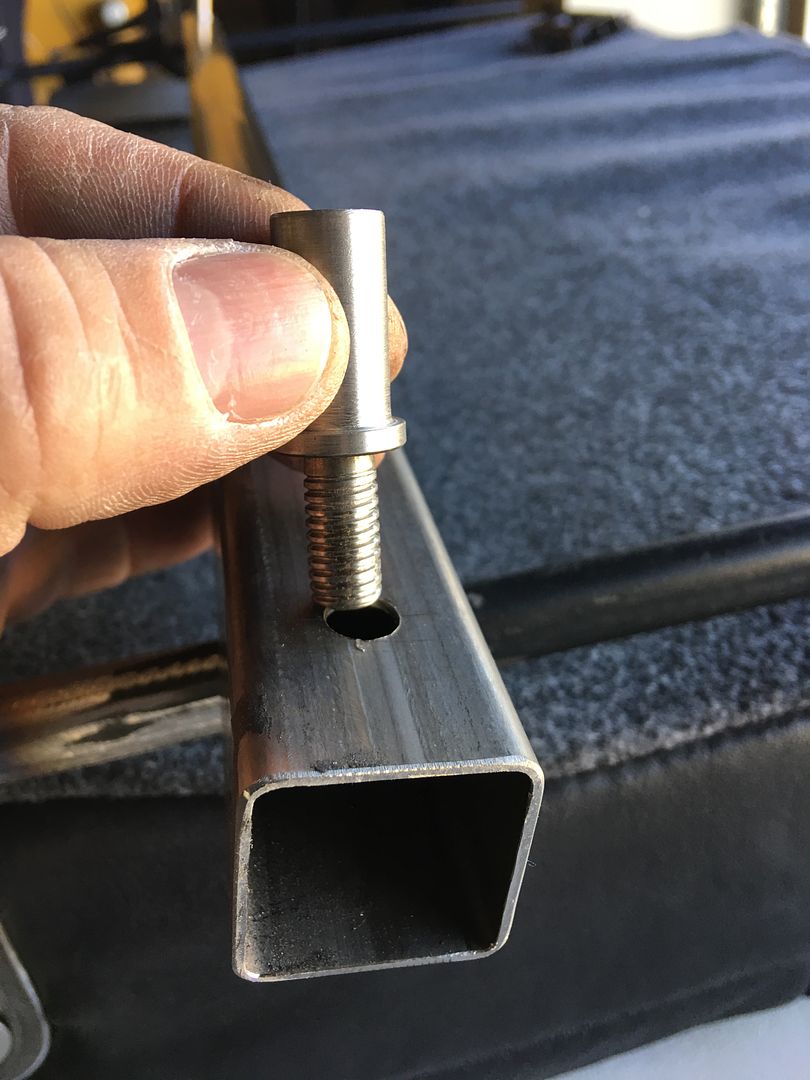
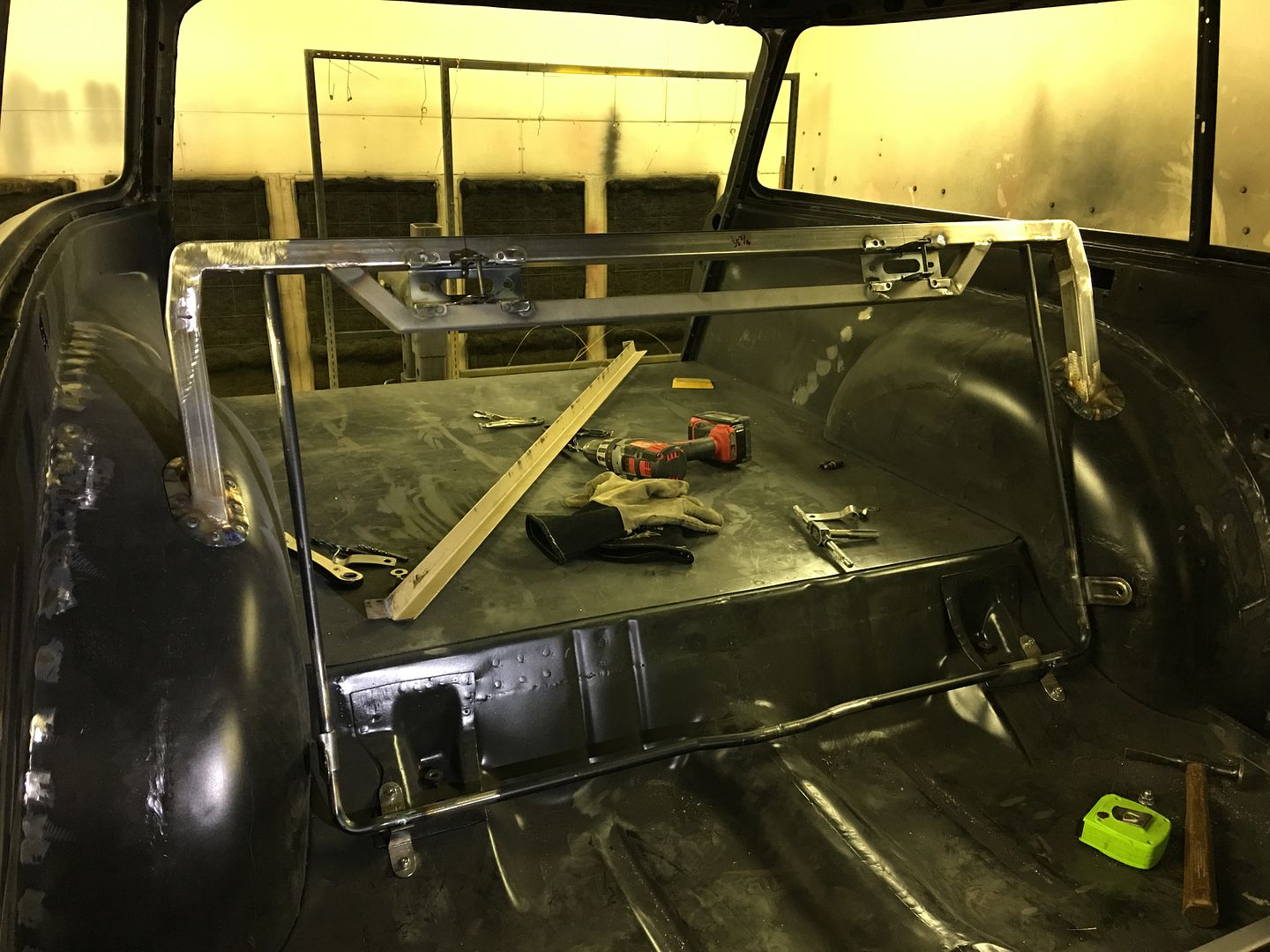
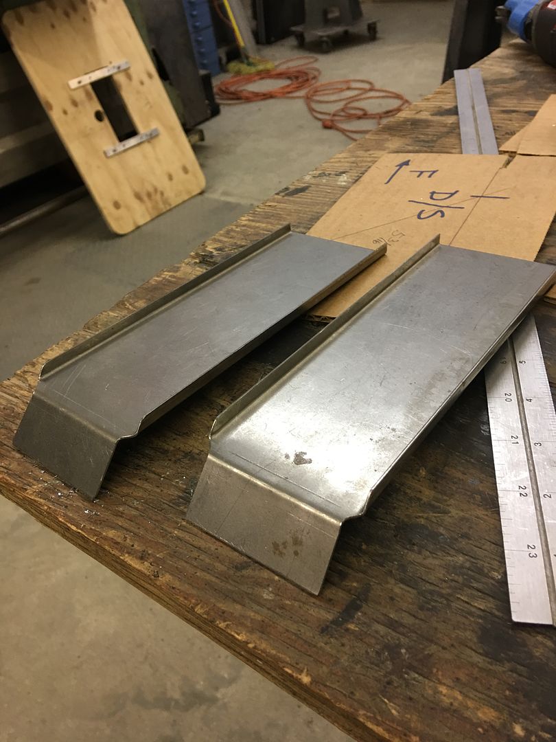
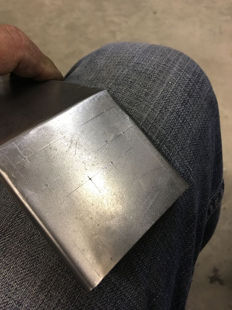
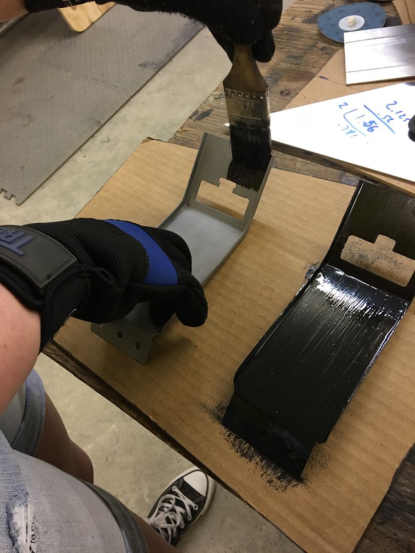
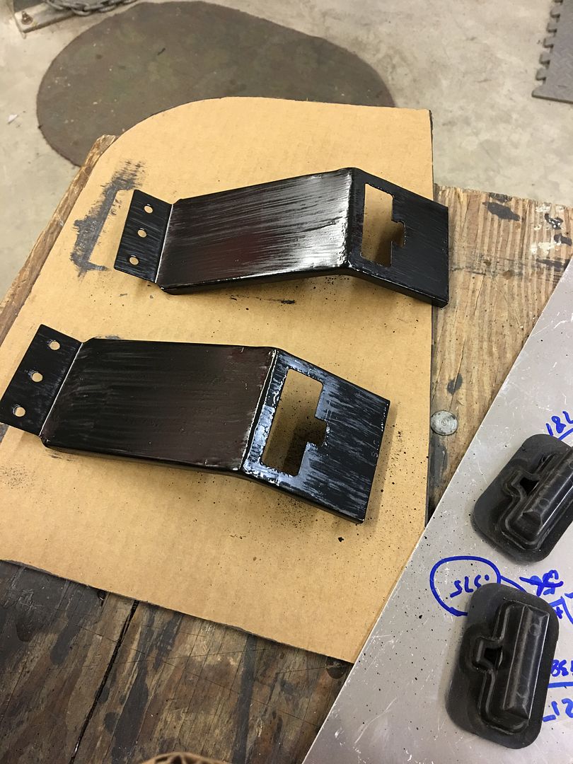
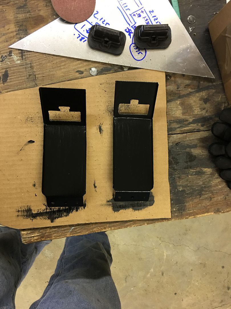
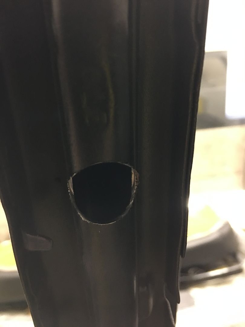
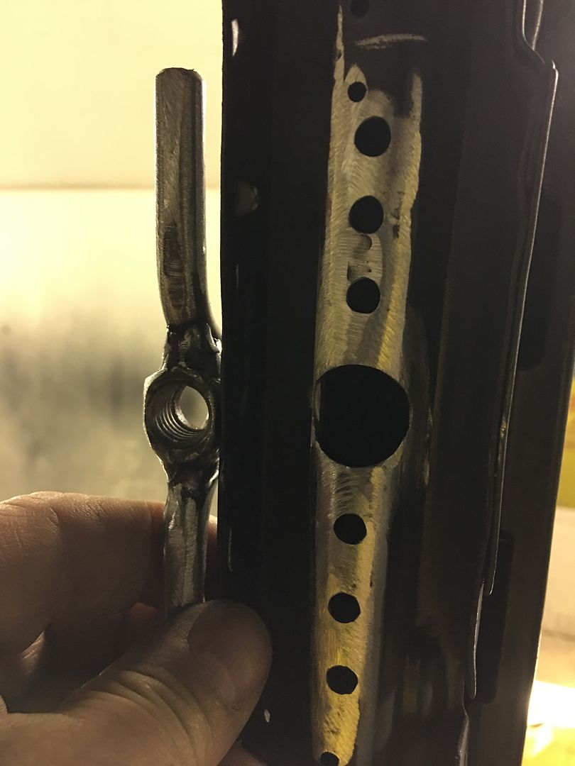
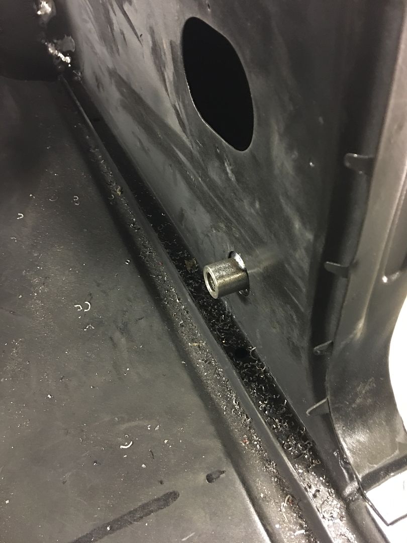
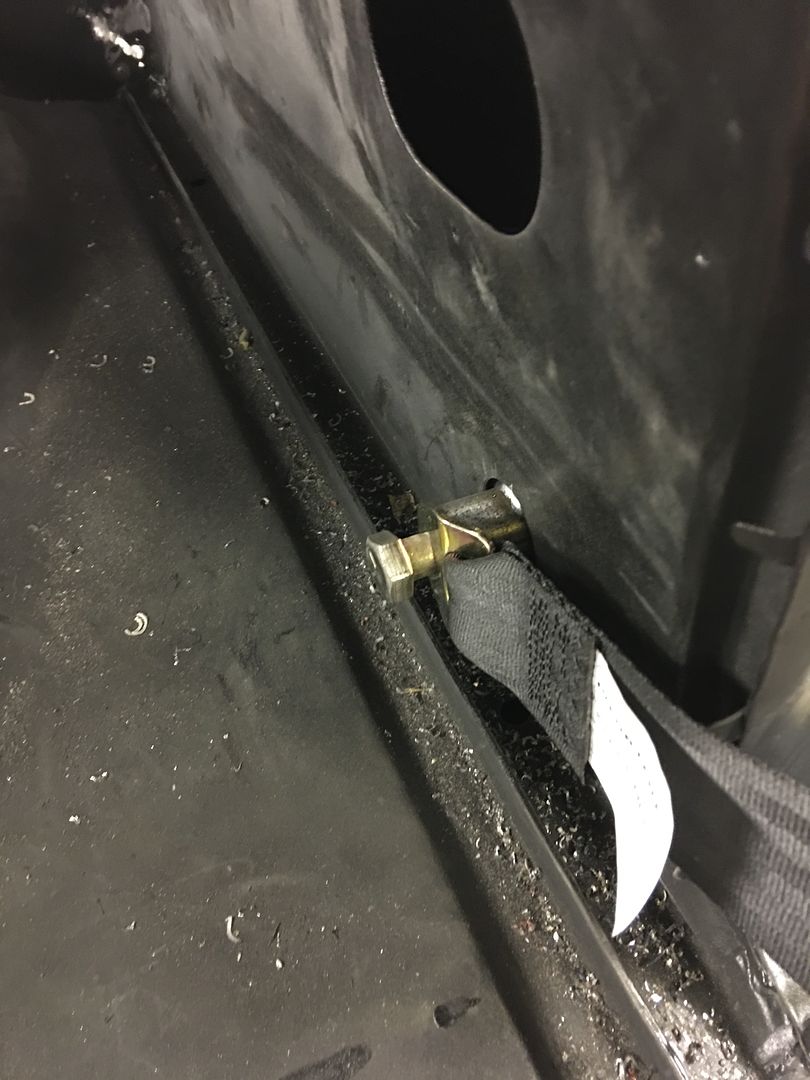
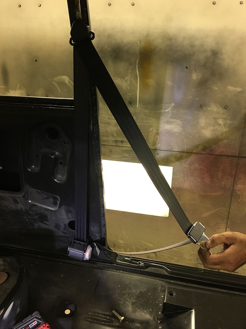
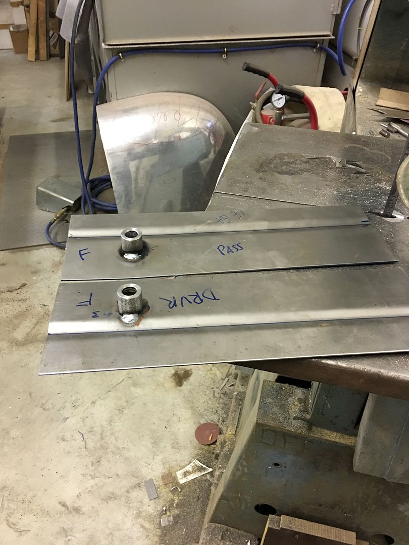
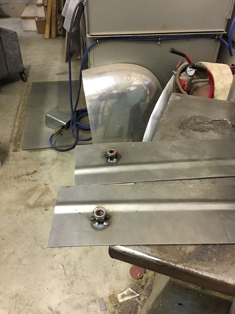
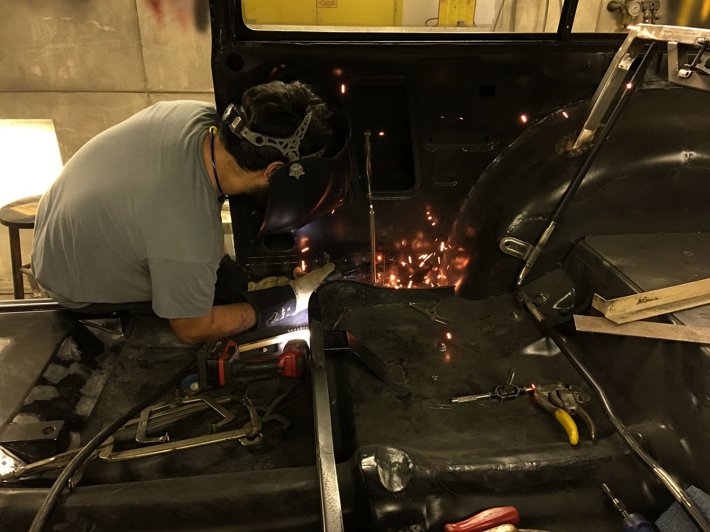
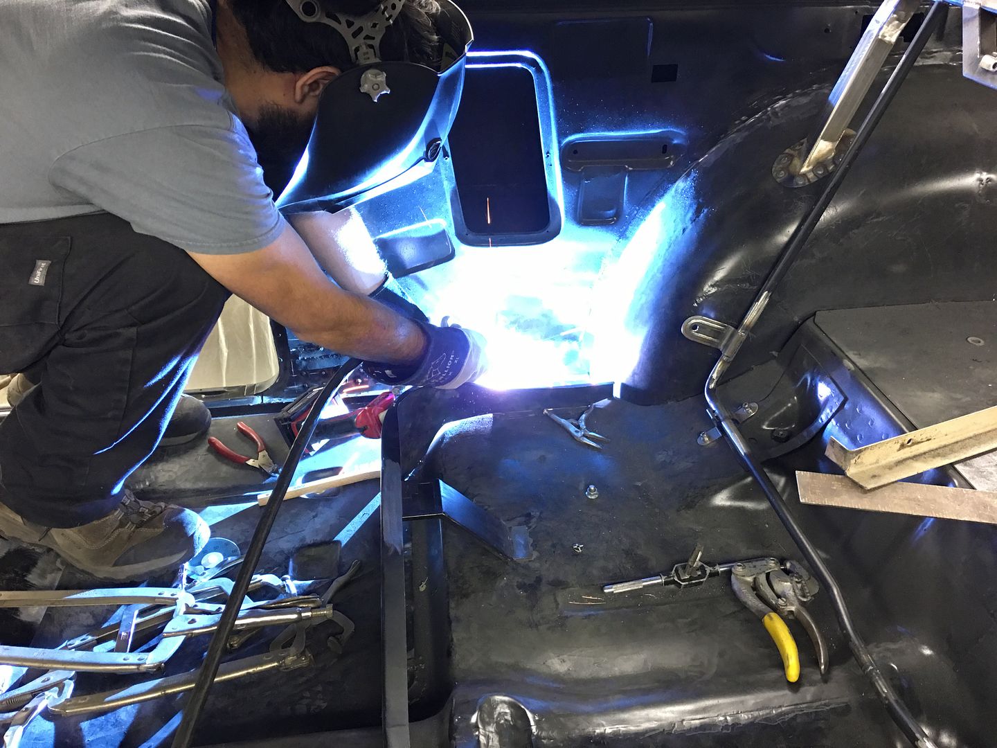
Getting some seat brackets welded in...
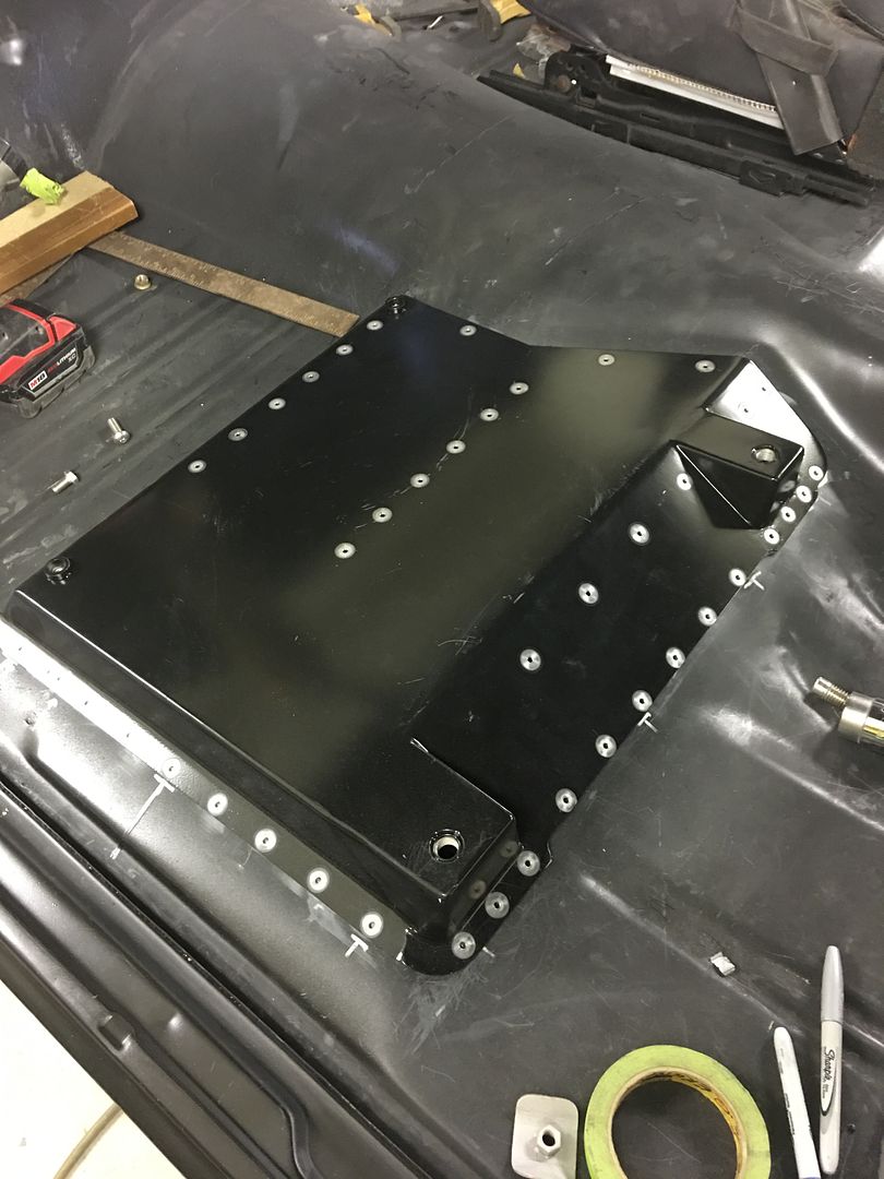
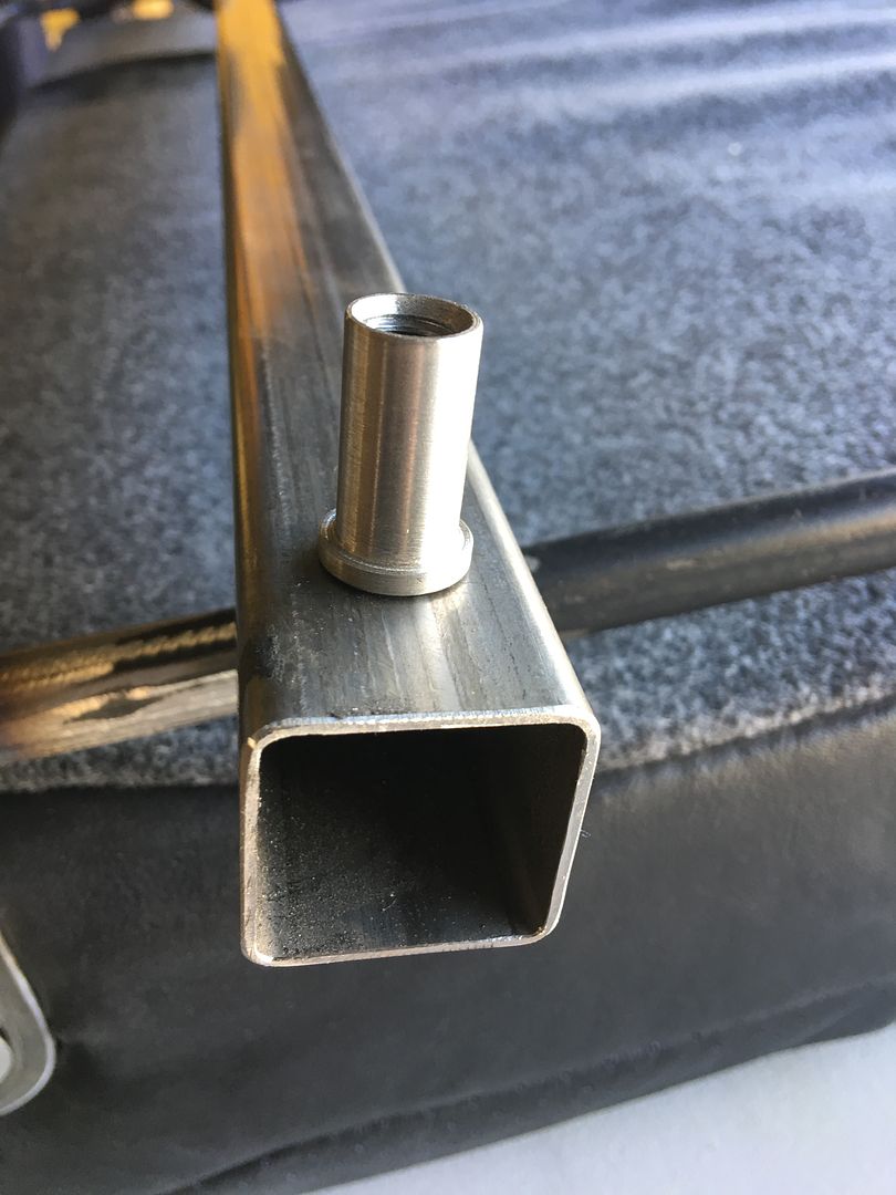
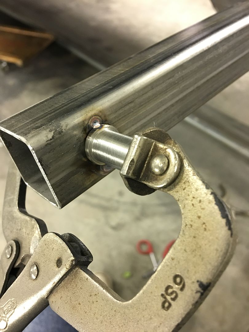
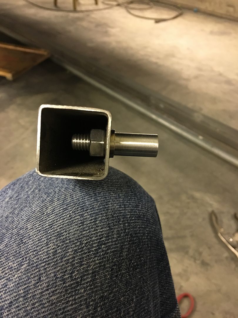
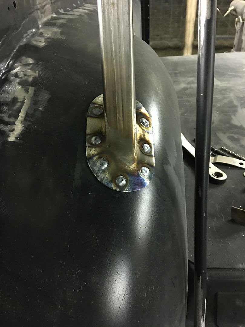
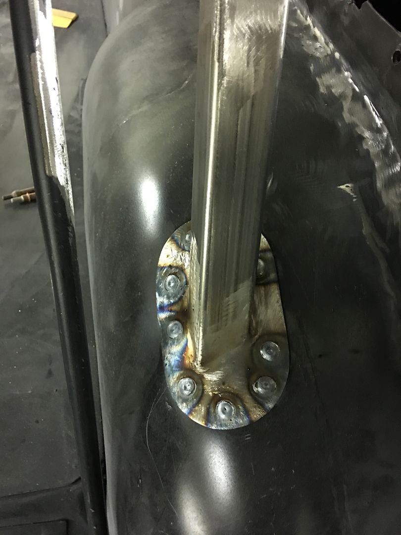
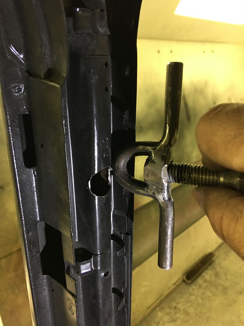
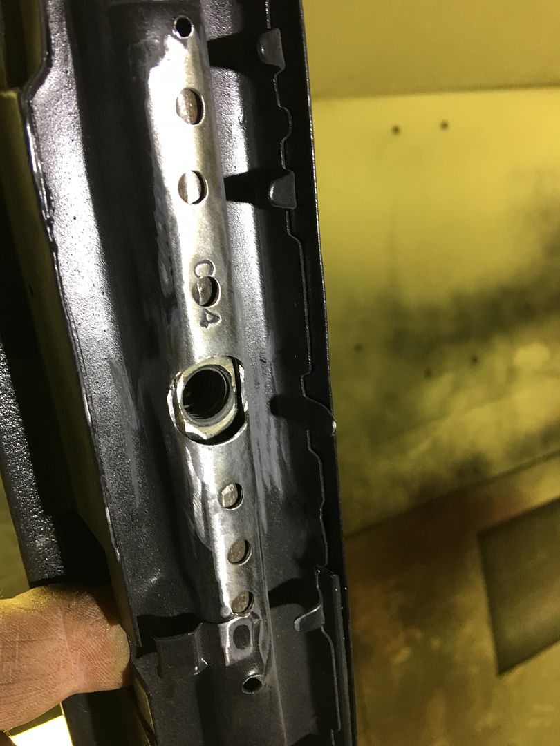
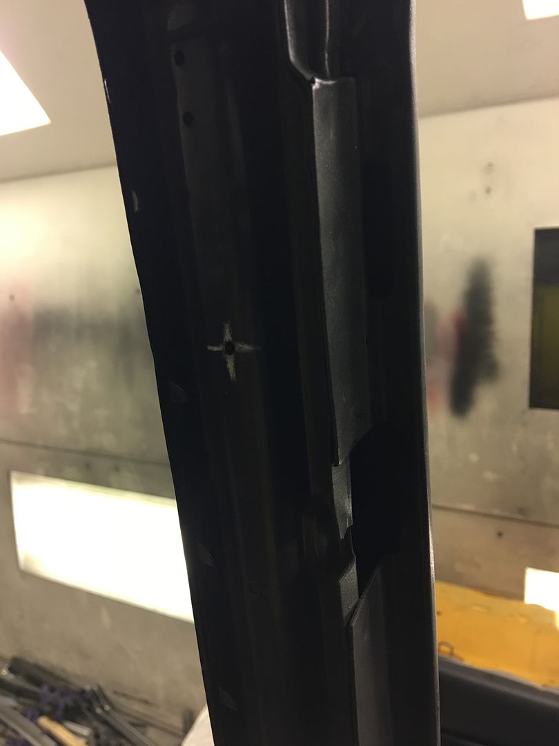
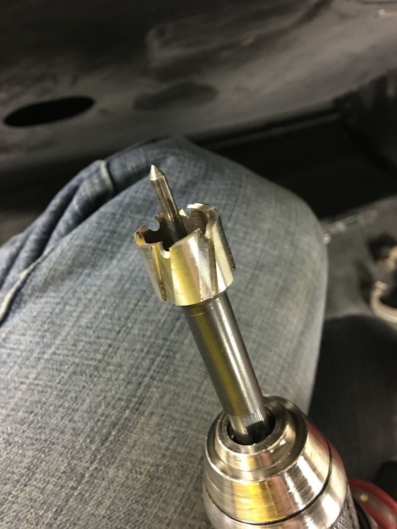
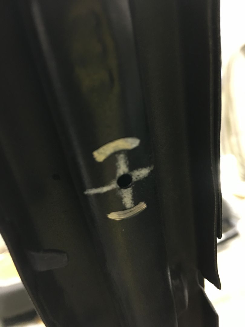
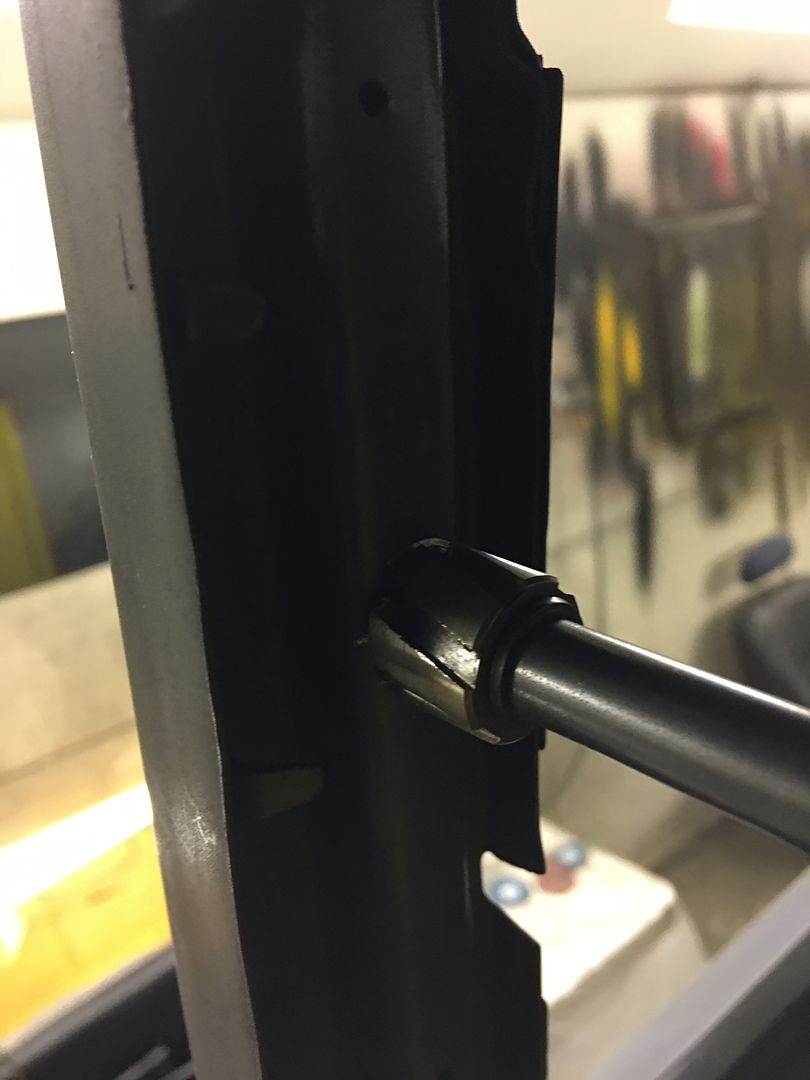
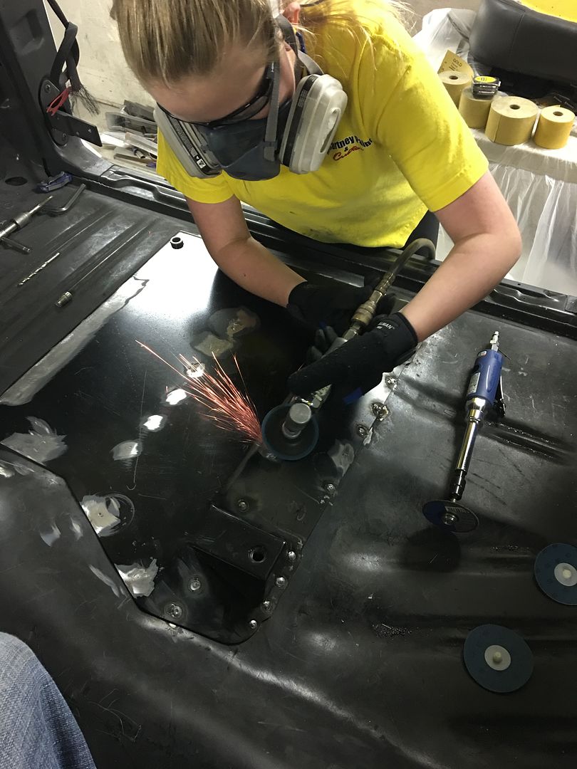
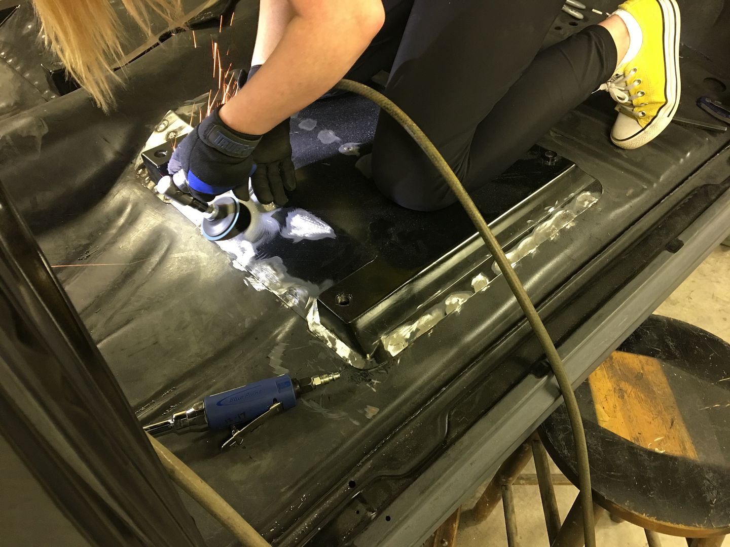
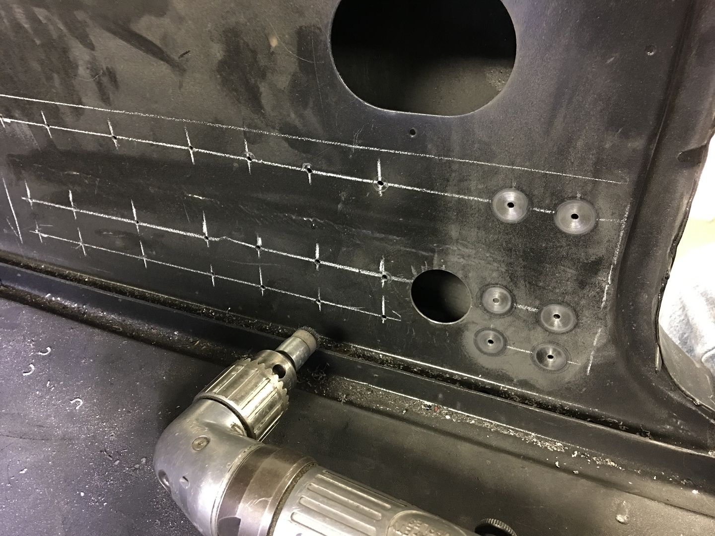
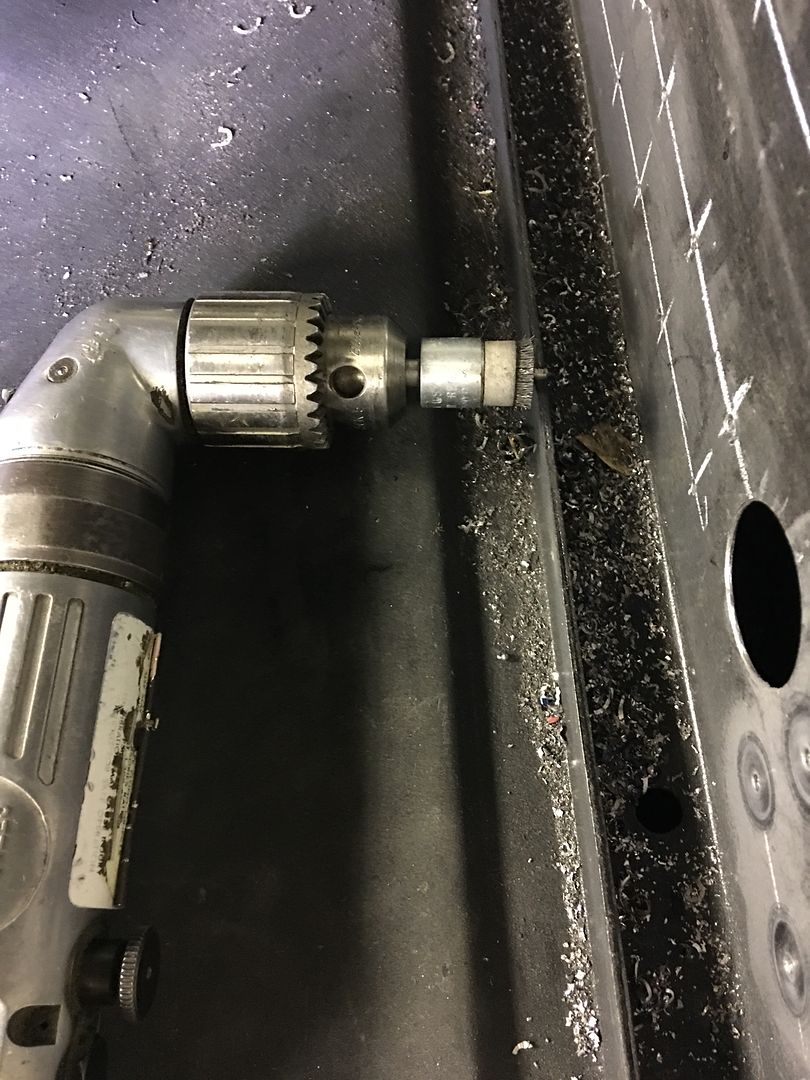
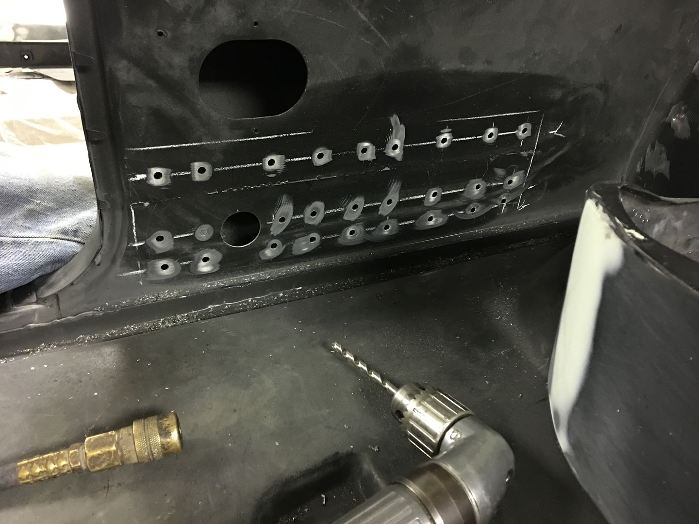
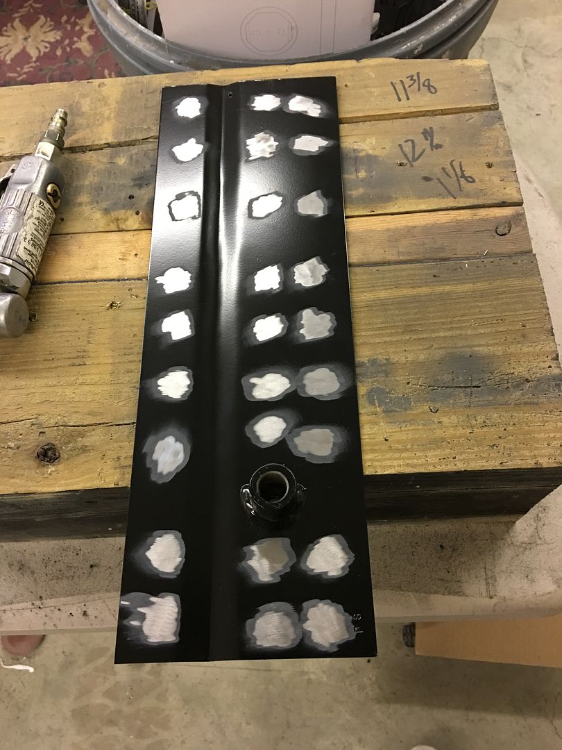
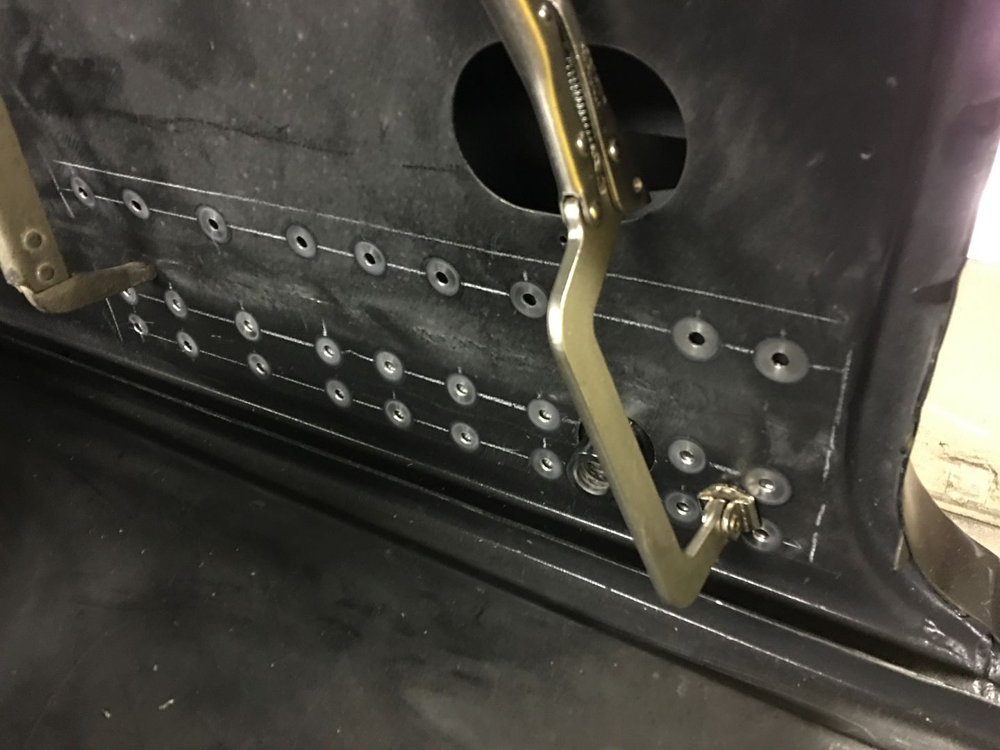

IMG_2593.jpg


Plug welding...


IMG_2613.jpg


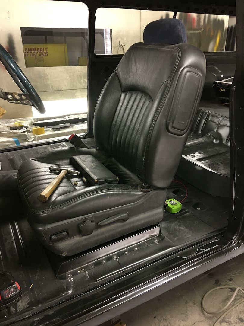
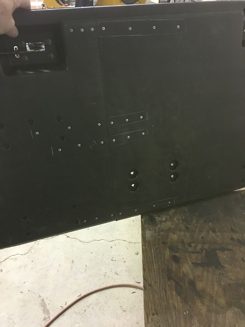
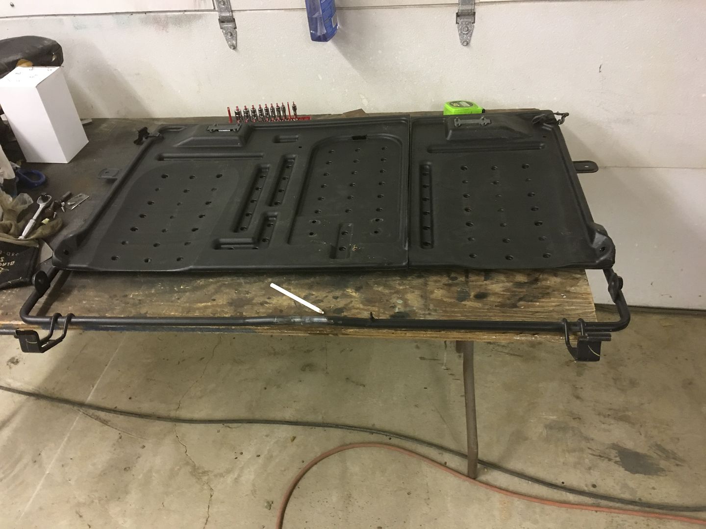
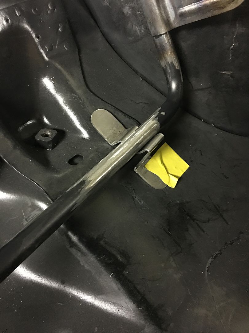
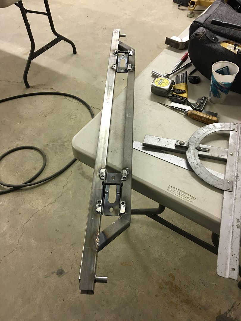
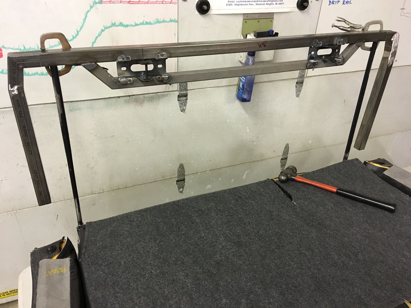
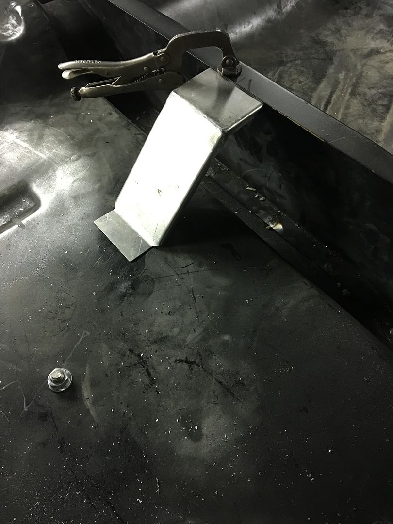
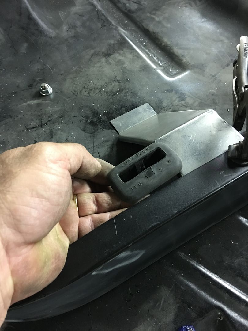
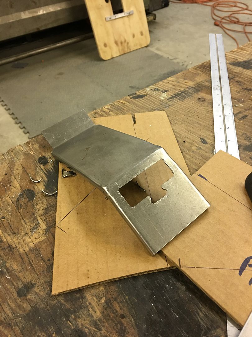
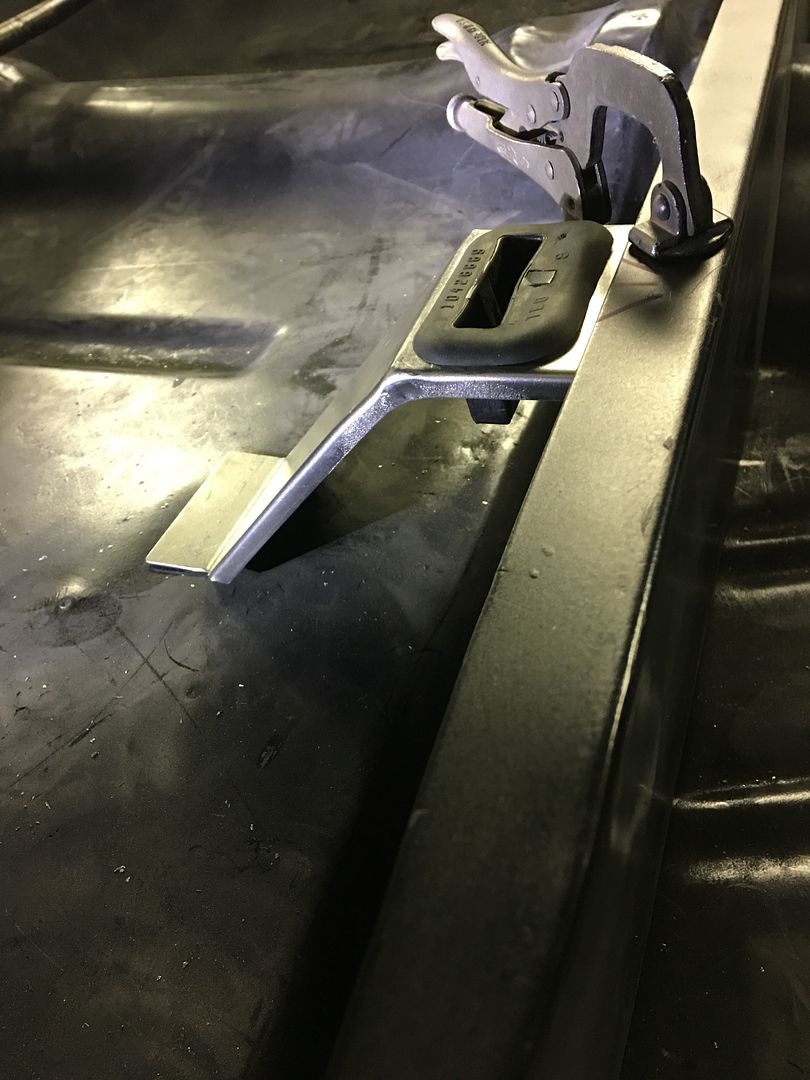
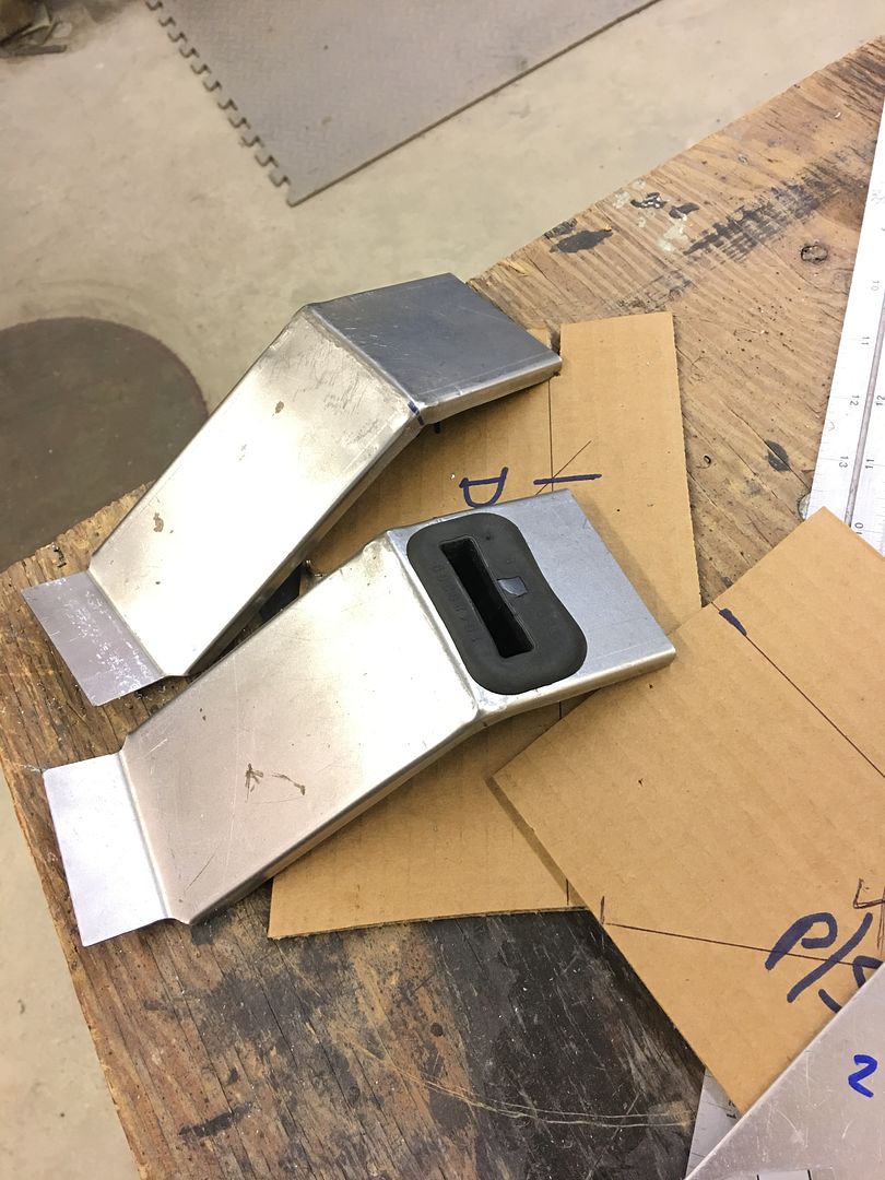
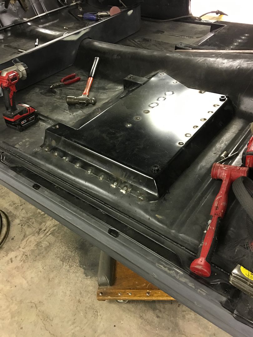
But before we get all the front seats in and make it harder to access the back, lets get the seat riser plug welded in for the back seat...


IMG_2615.jpg


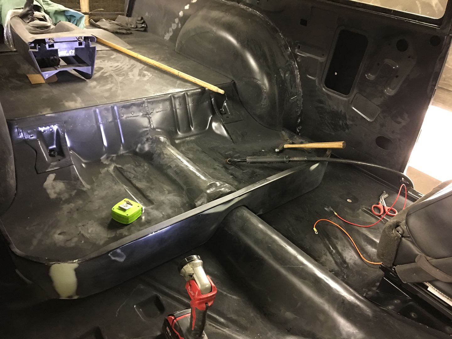
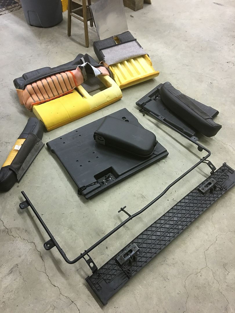
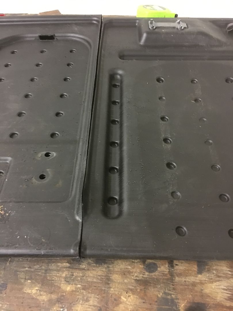
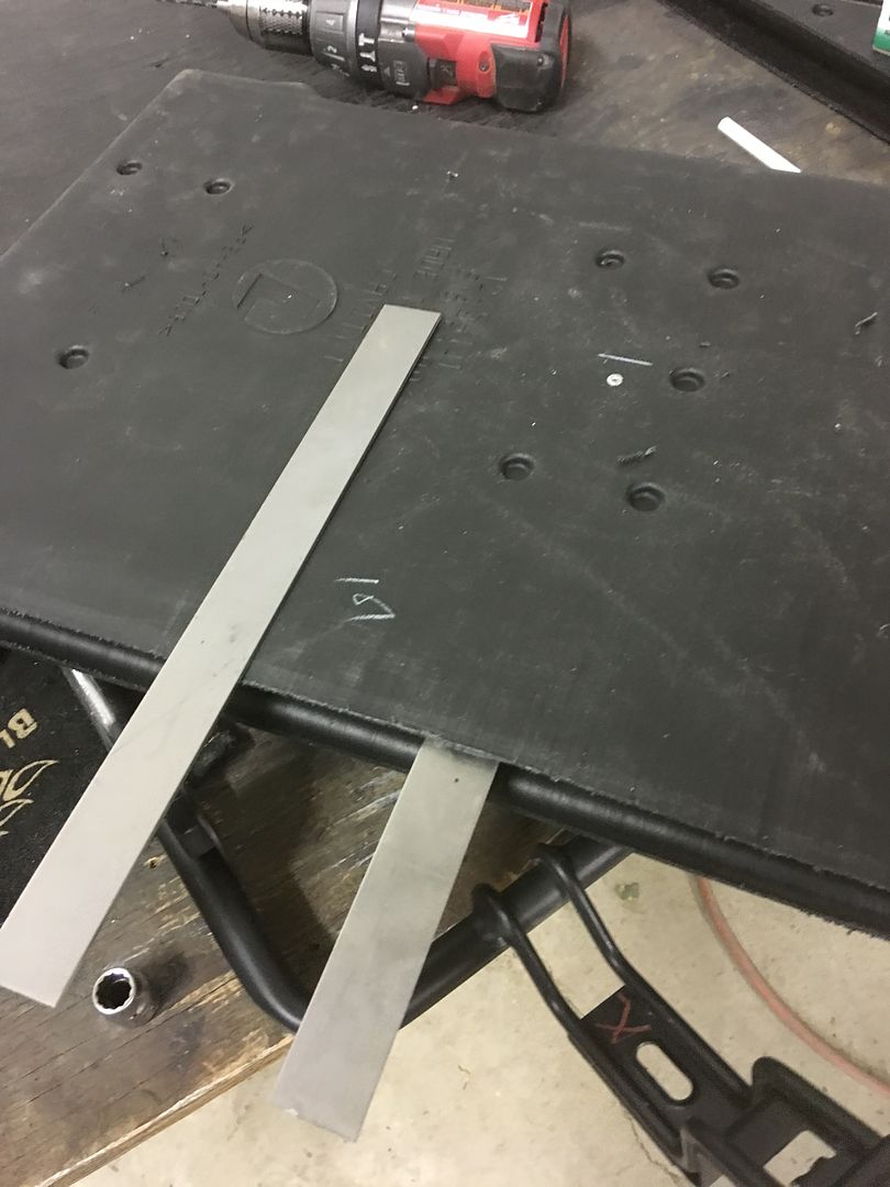
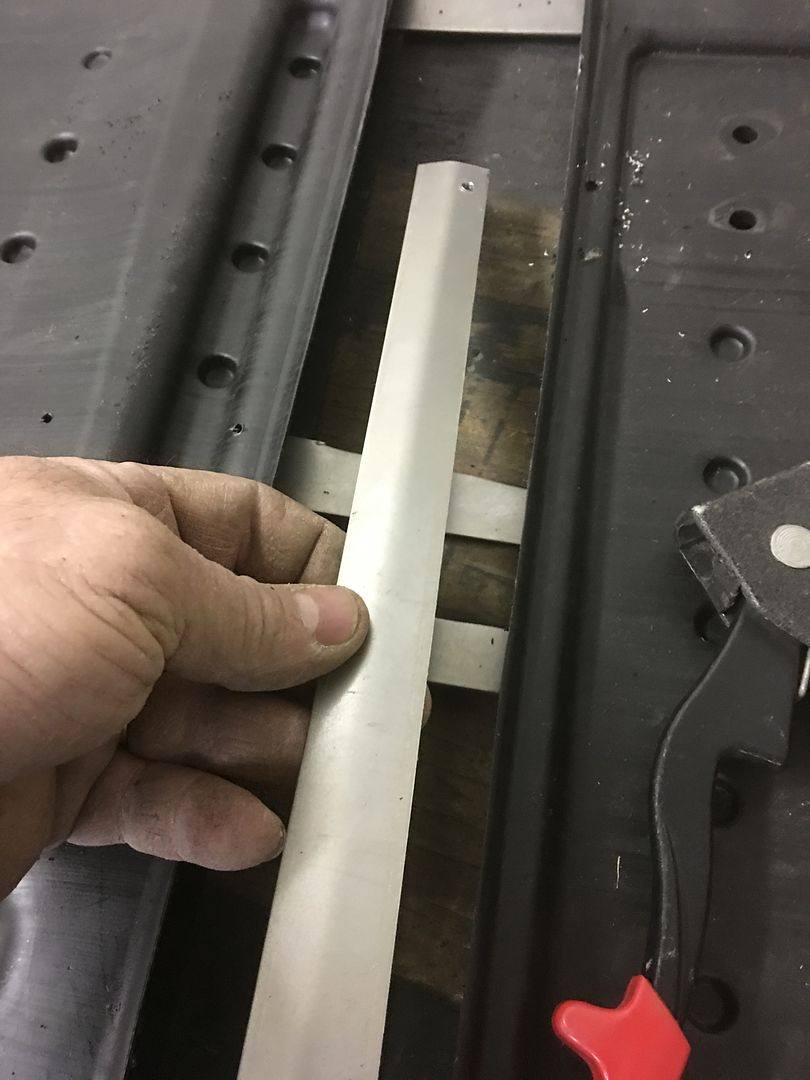
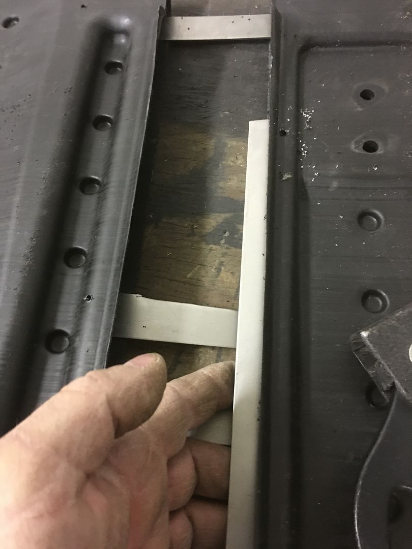
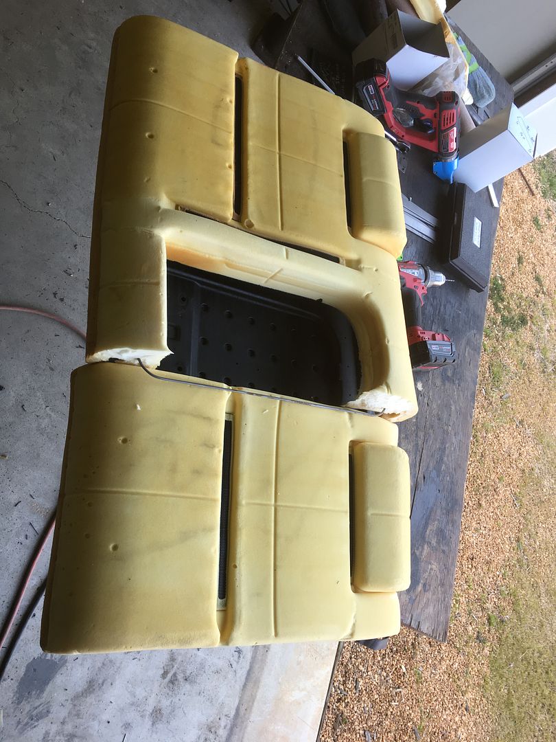
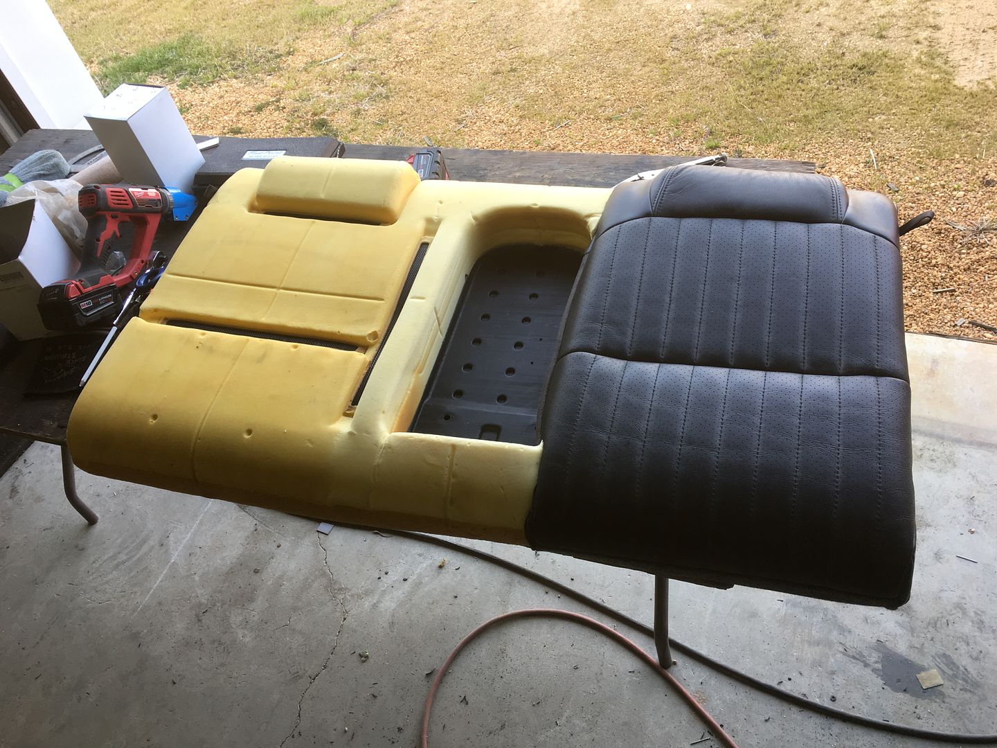
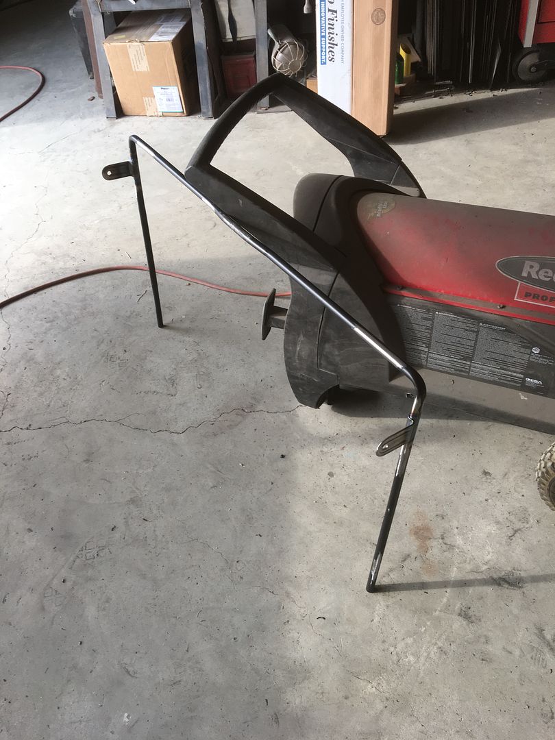
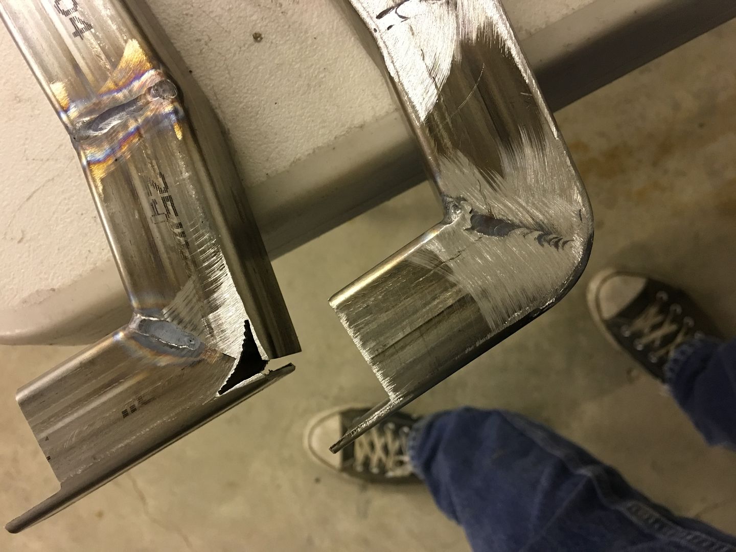
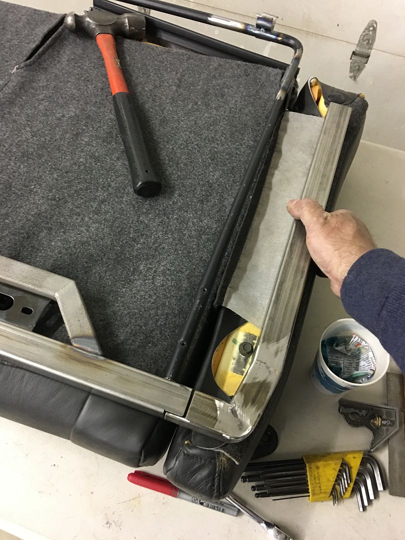
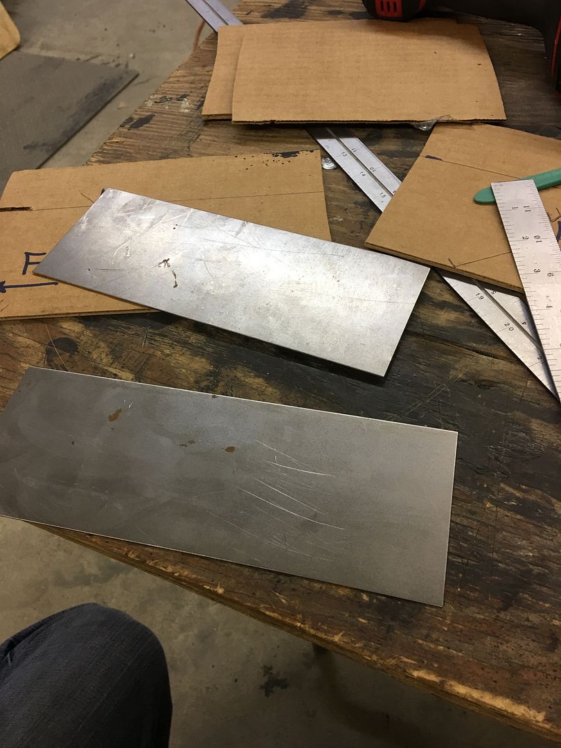
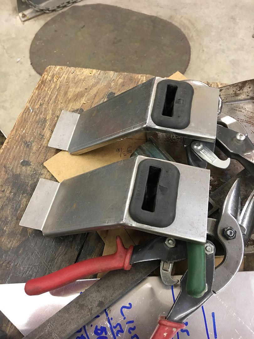
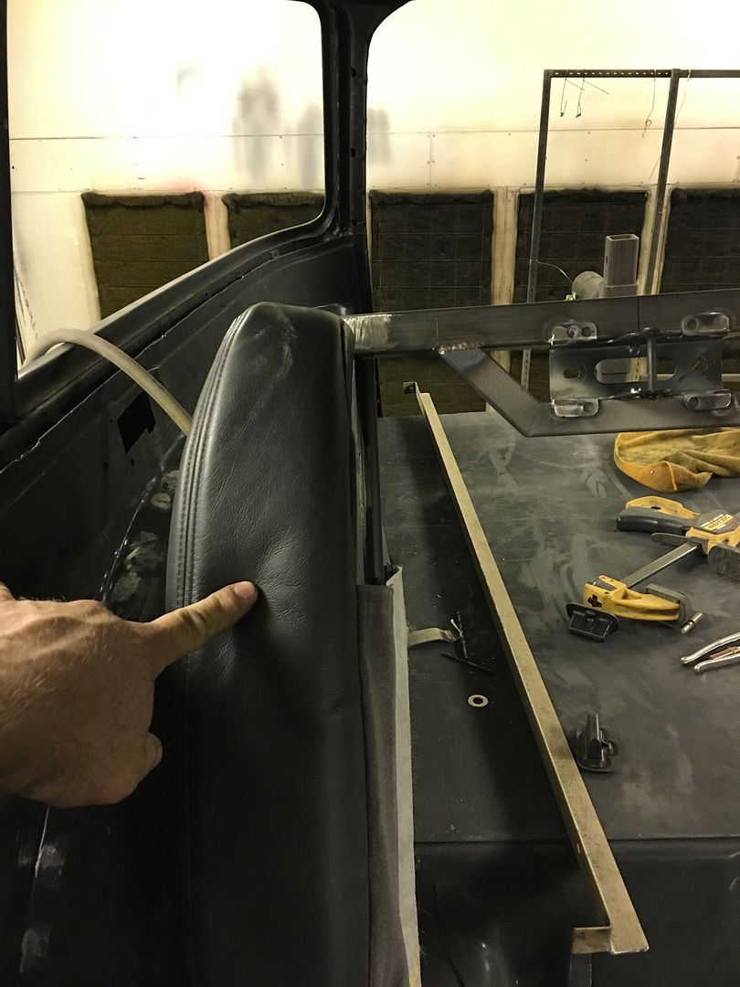
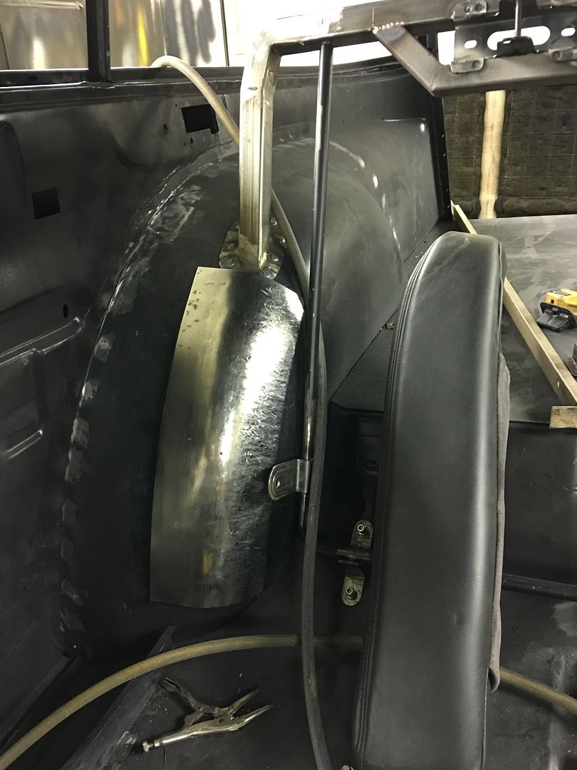
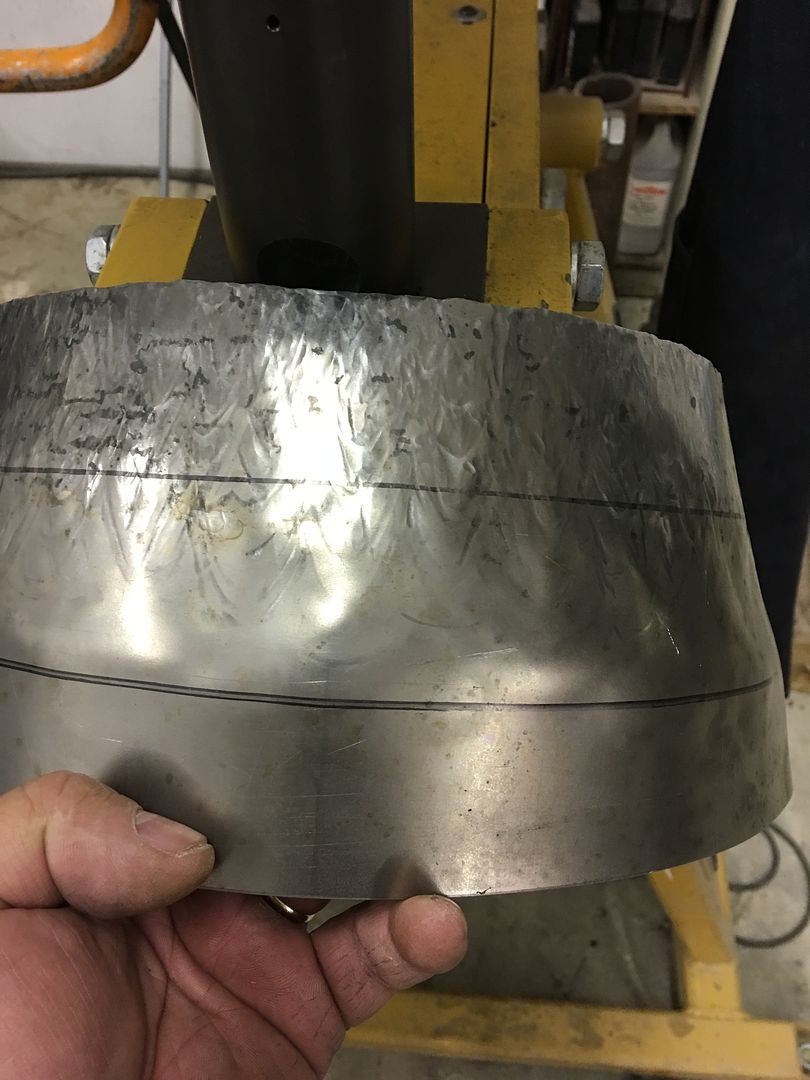
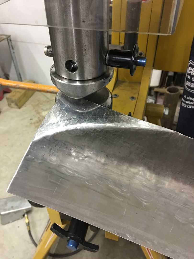
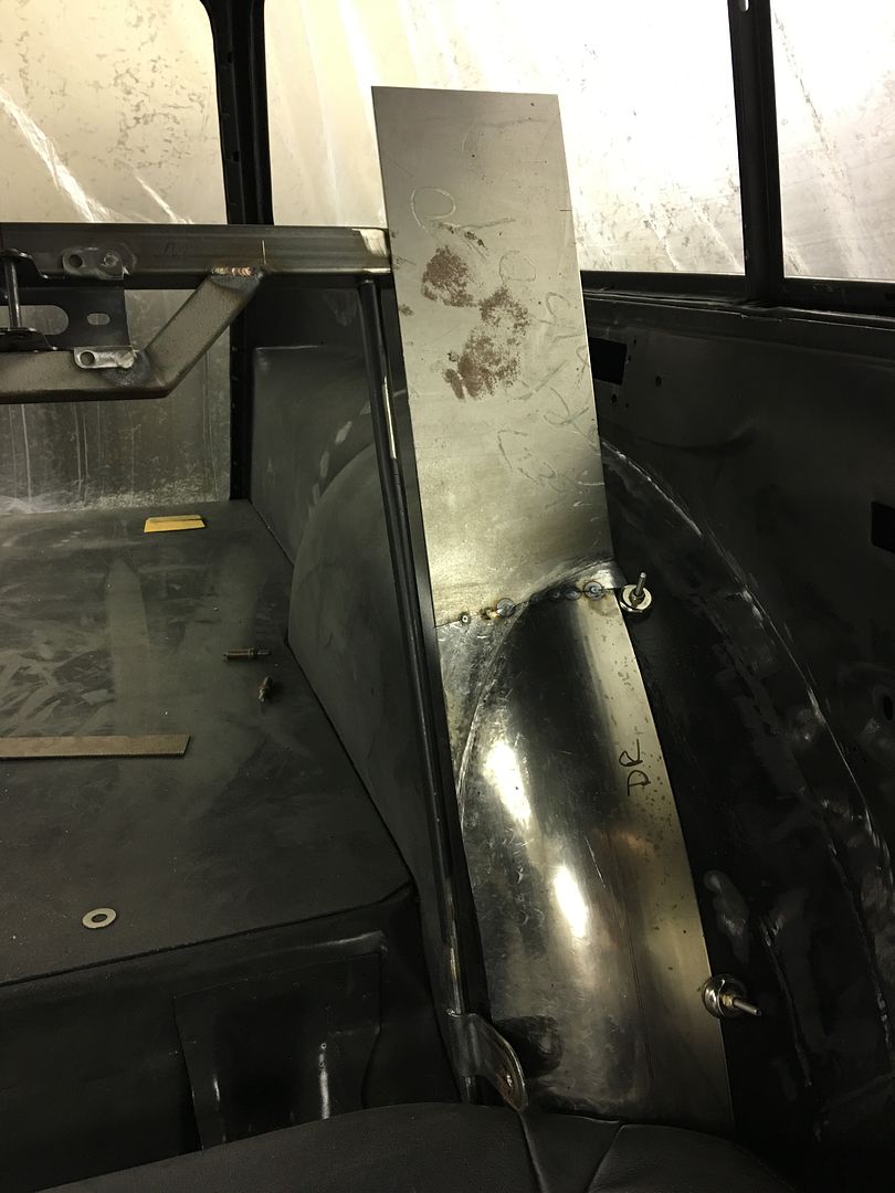
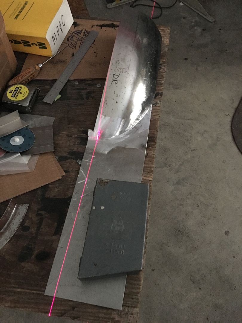
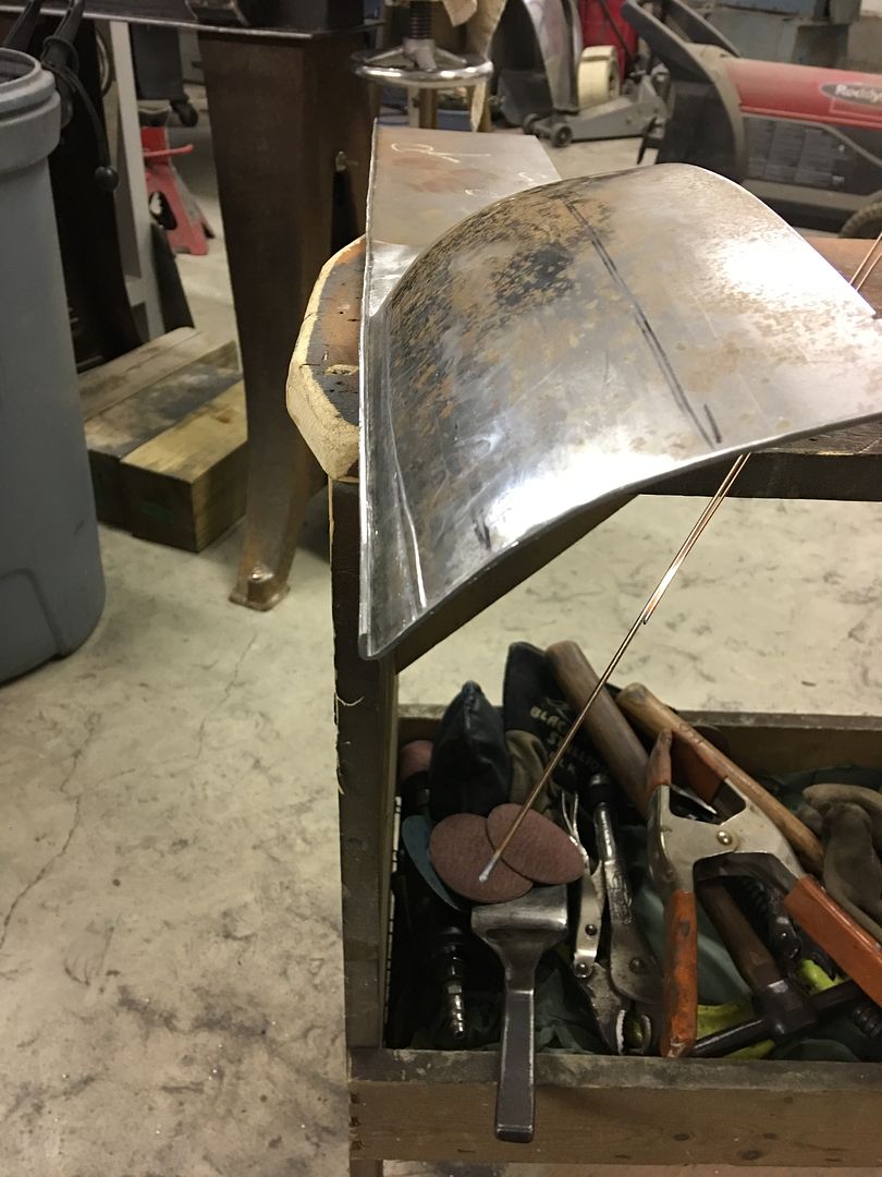
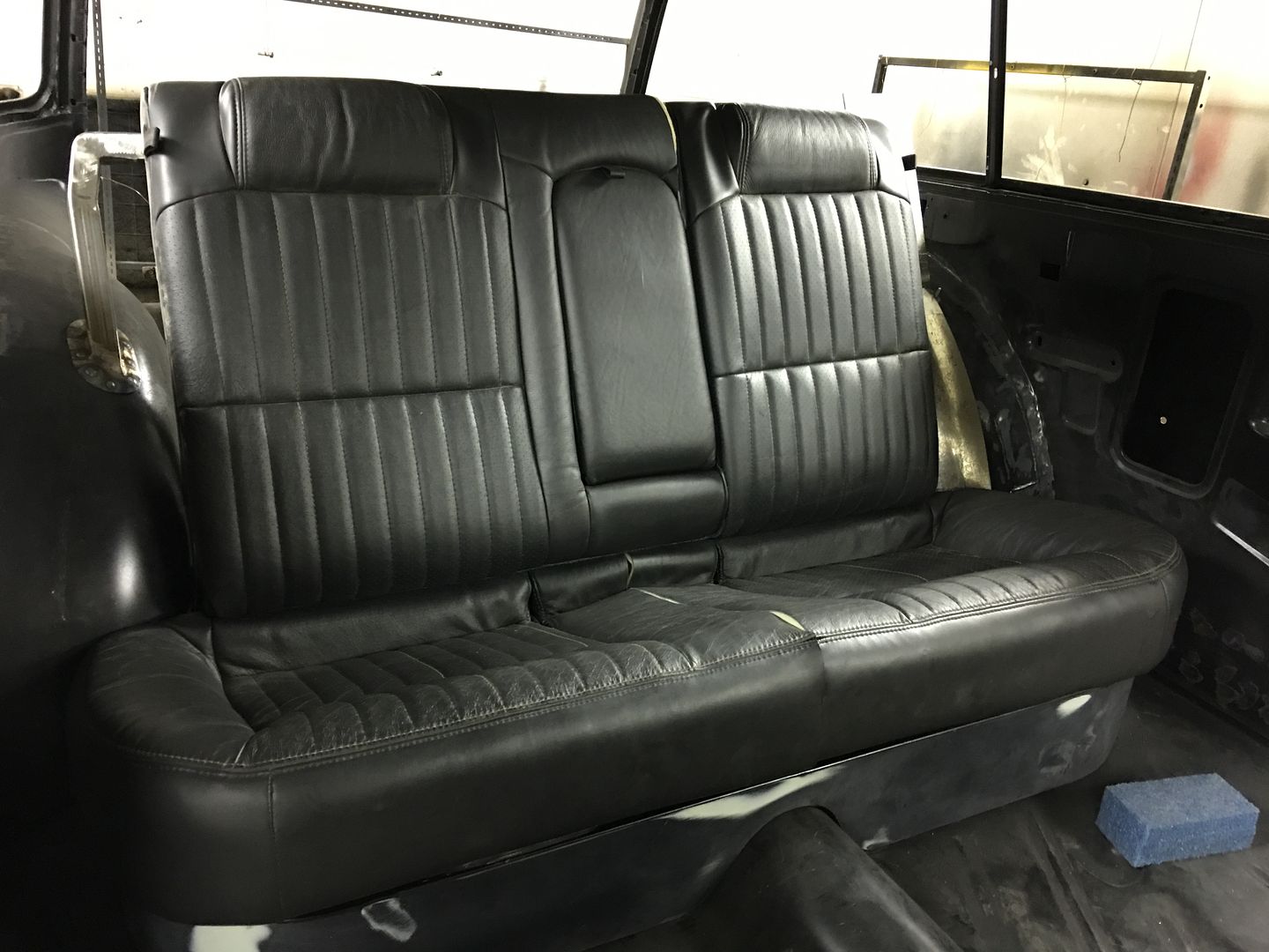
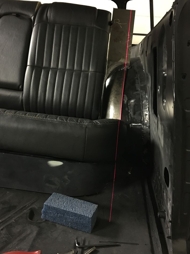
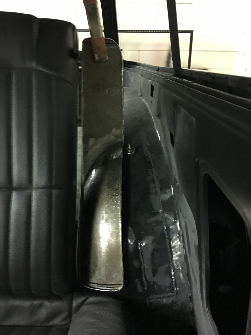
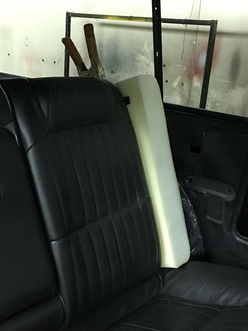
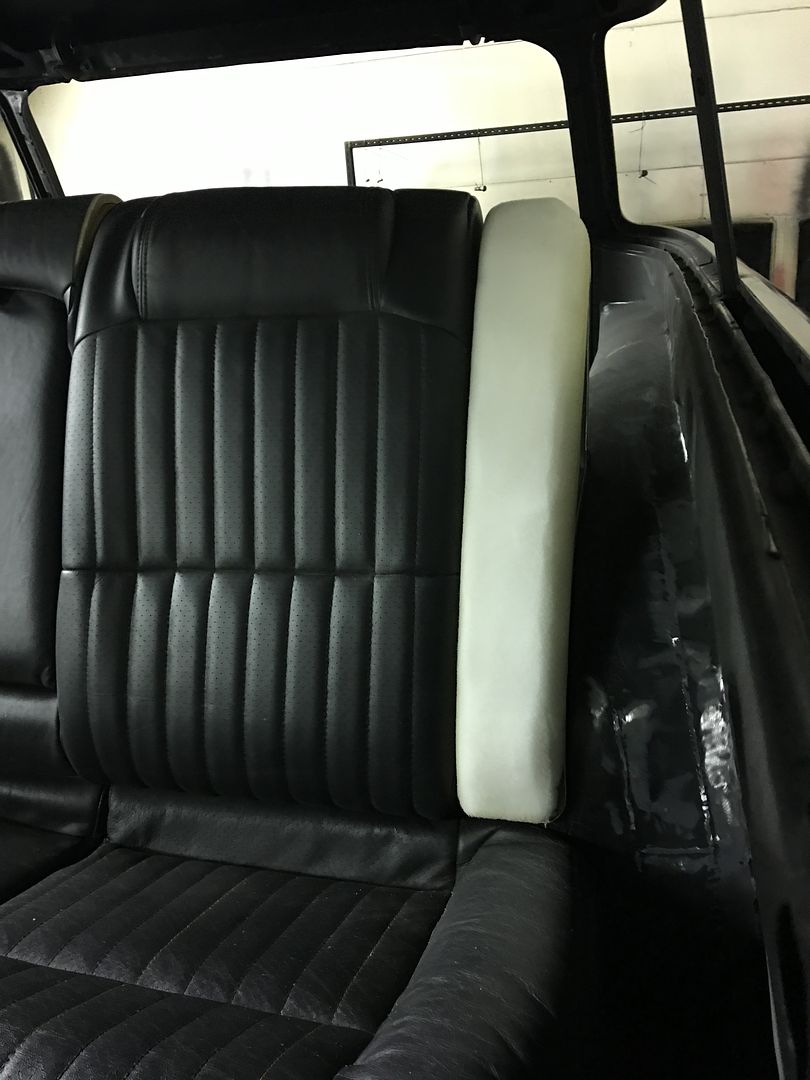
Next, our rear seat that came with the buckets was slightly oversize for our widened wheel wells. Some quick measurements showed we need to lose about 2" in width..


IMG_2616.jpg


IMG_2618.jpg


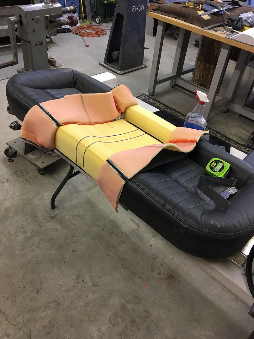
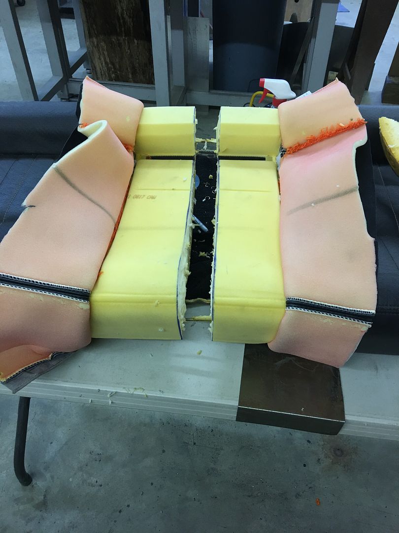
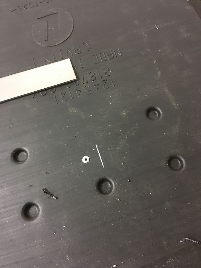
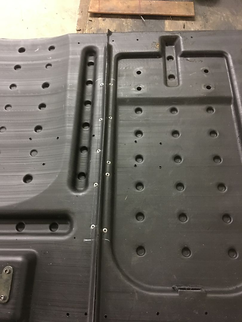
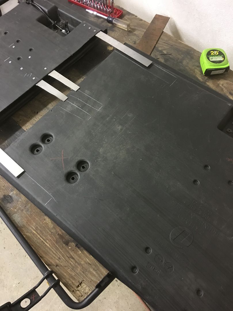
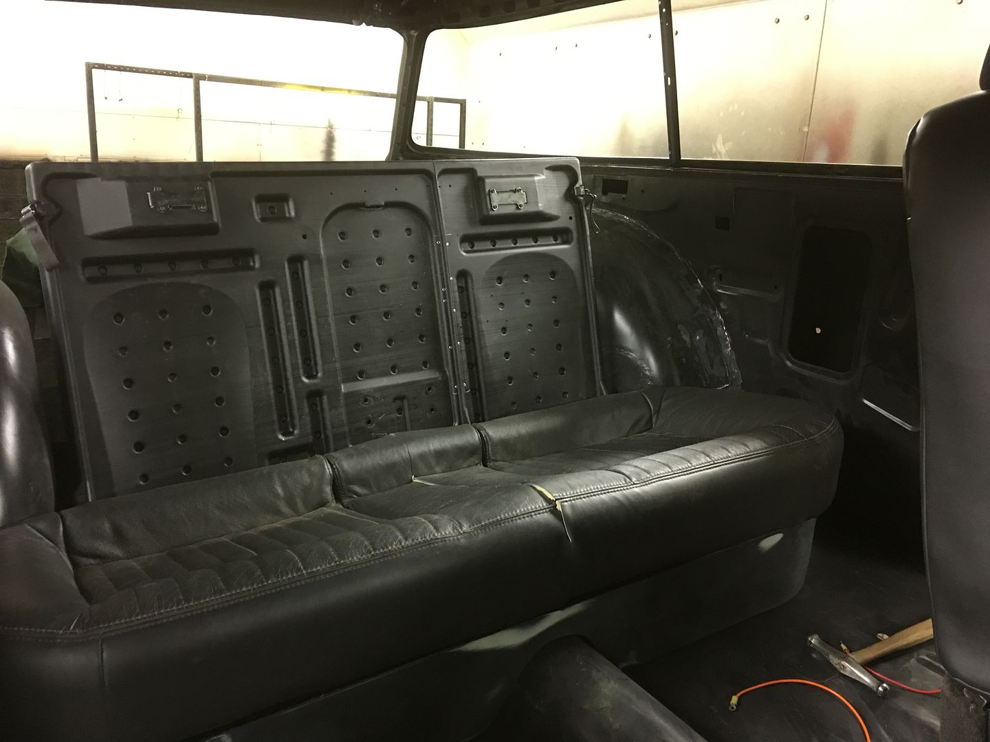
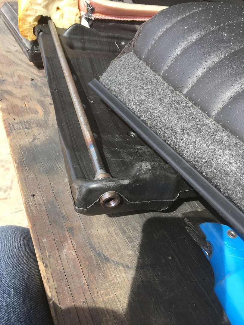
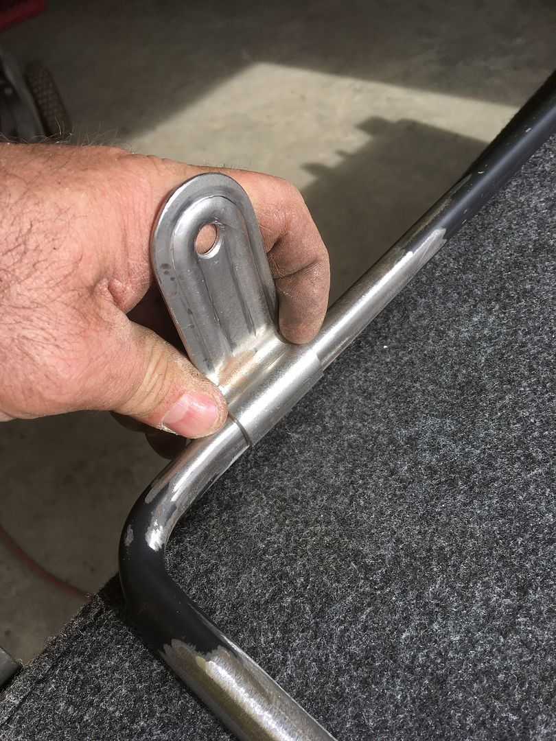
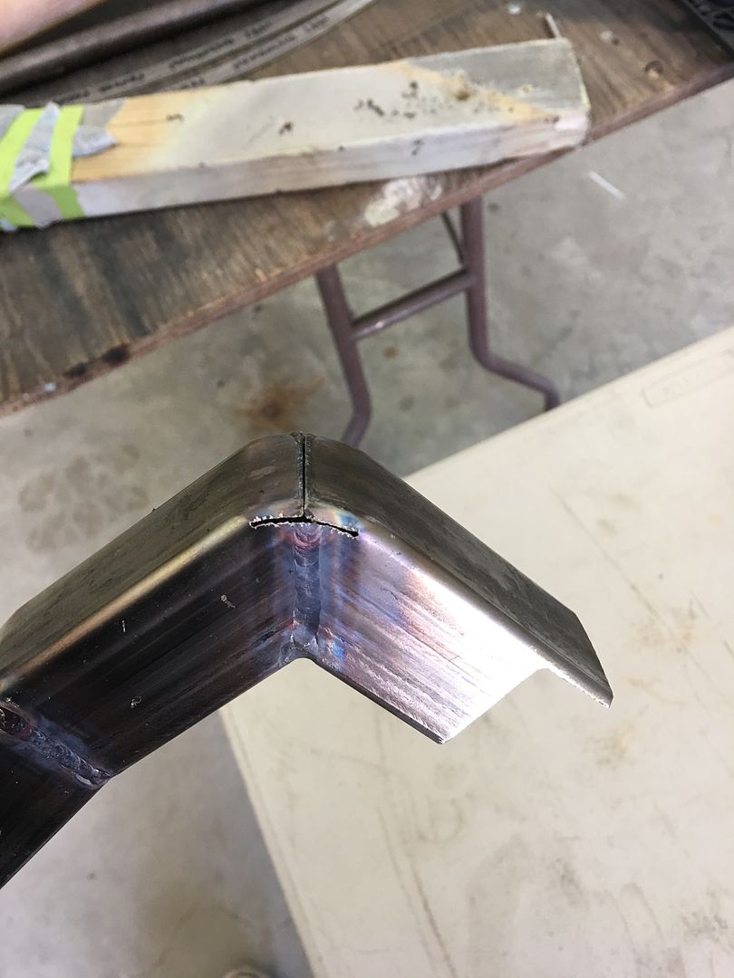
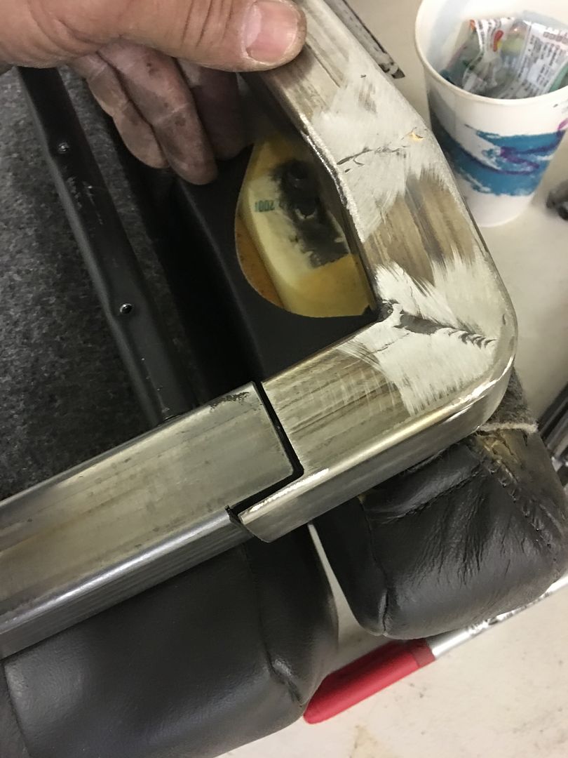
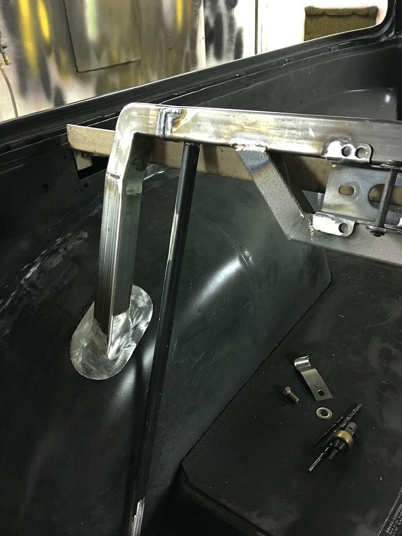
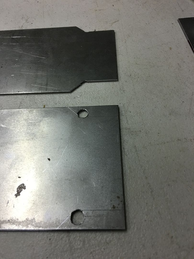
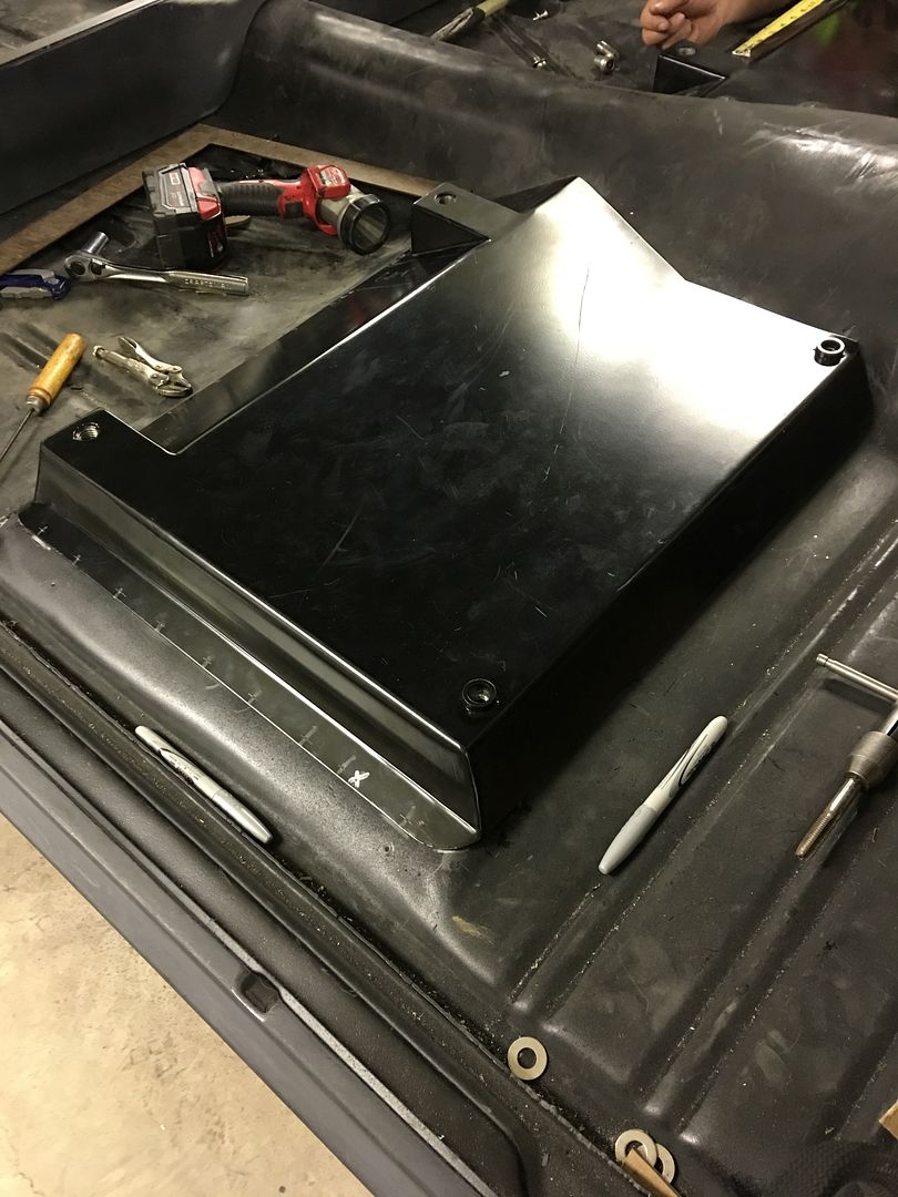
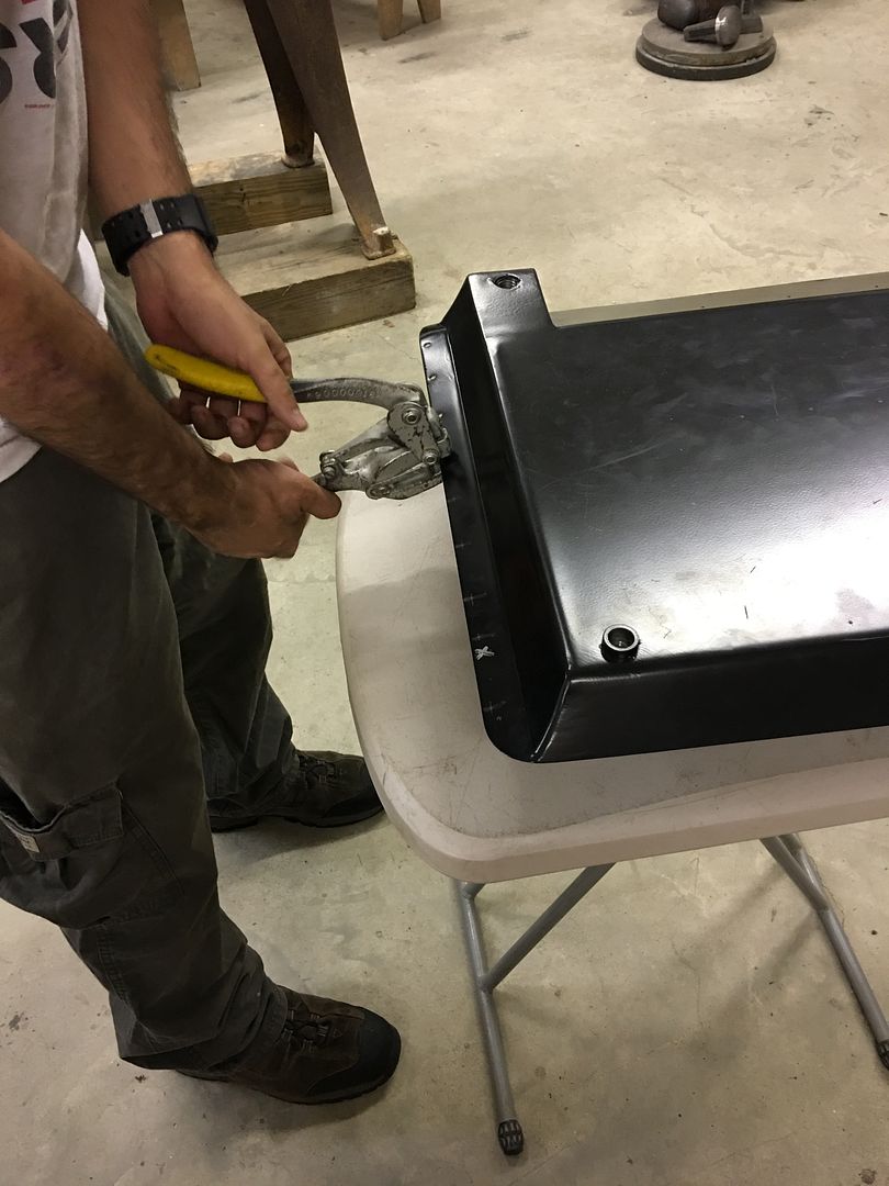
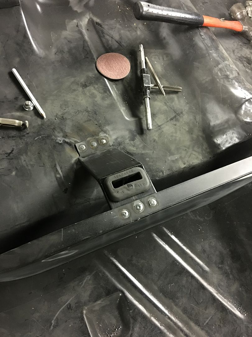
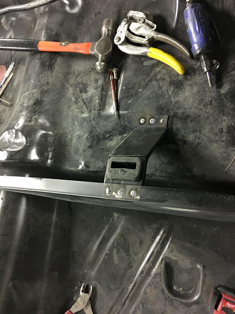
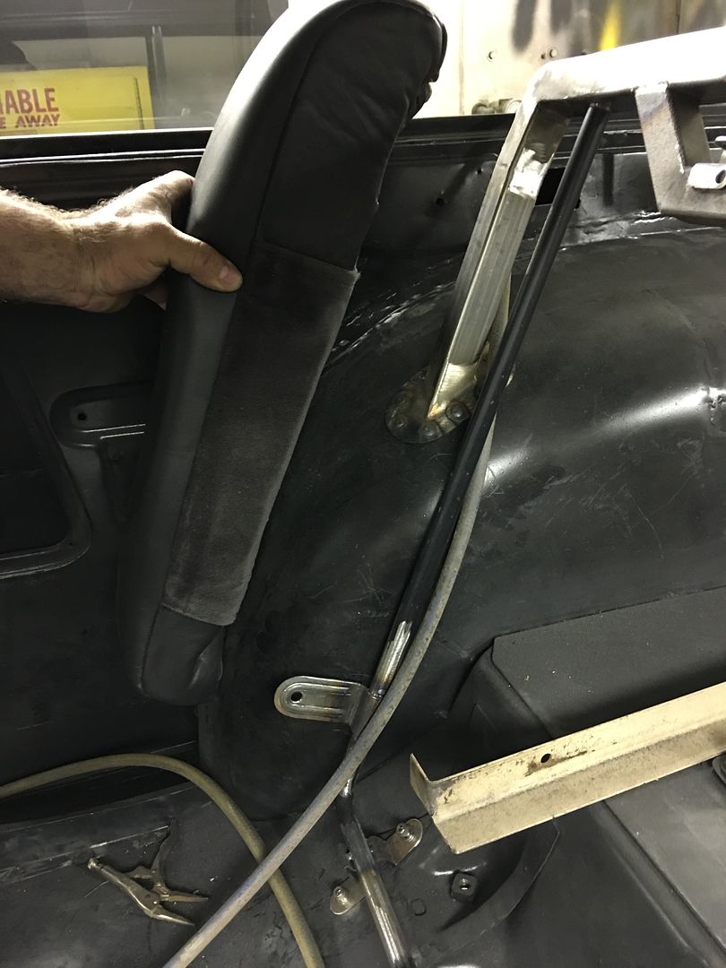
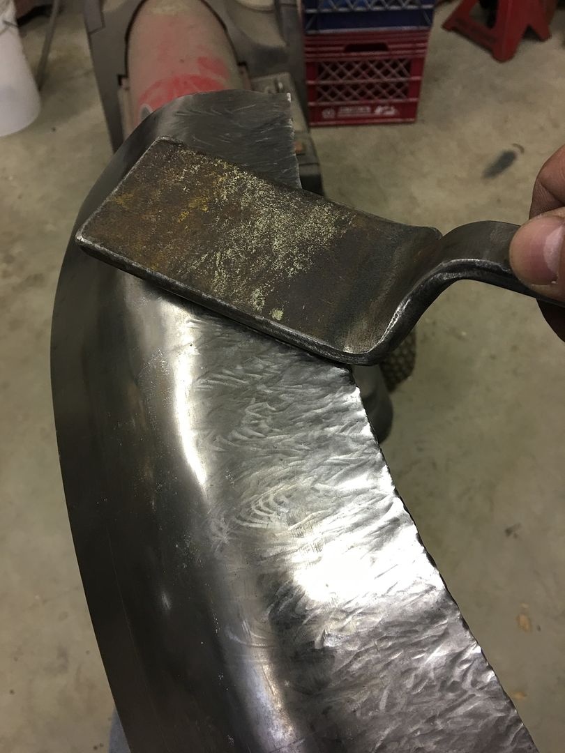
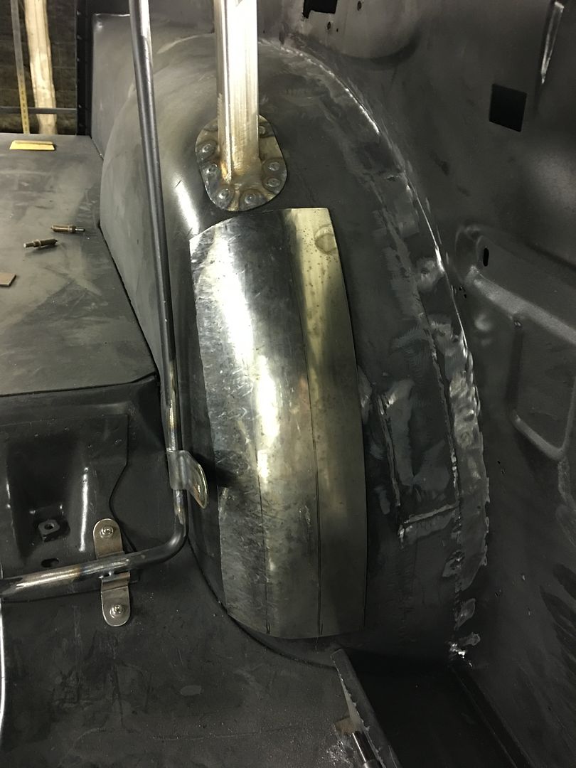
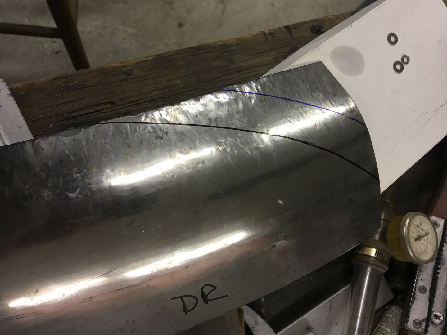
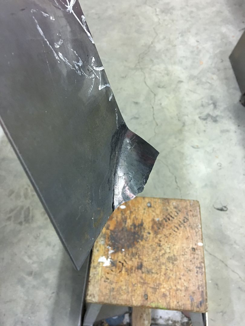
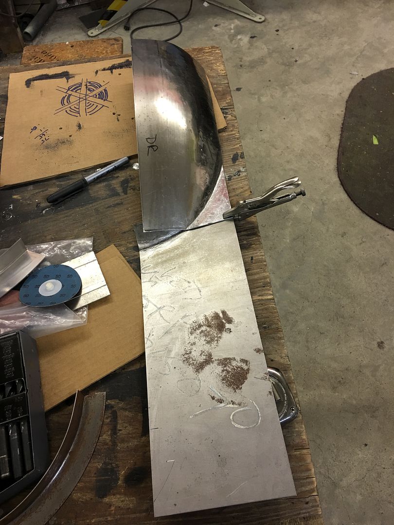
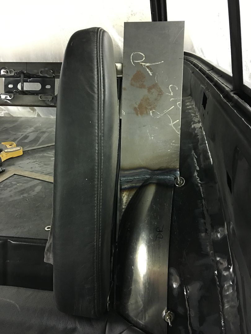
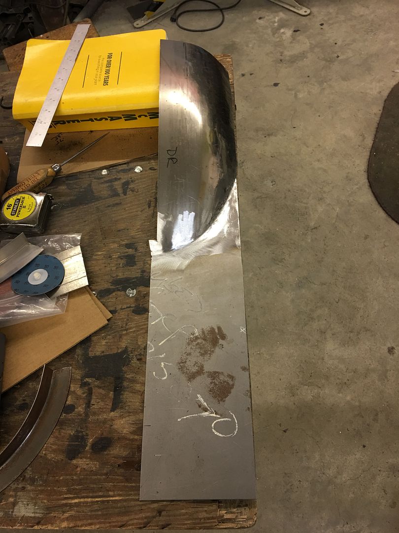
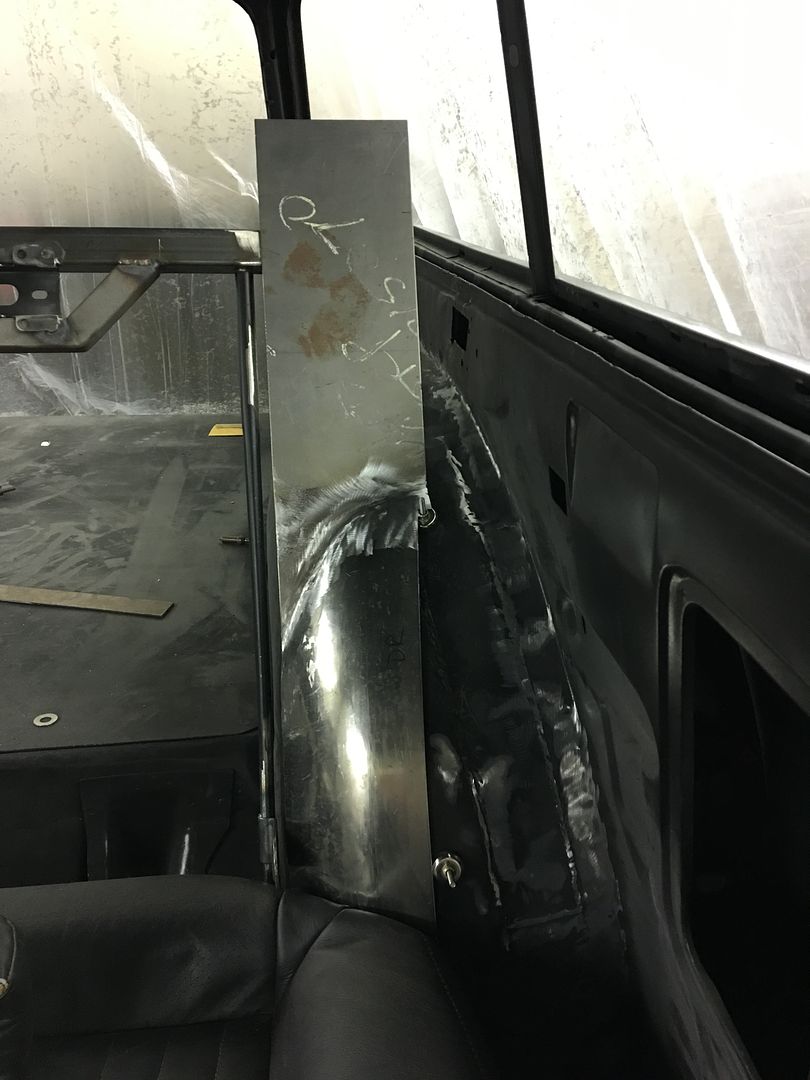
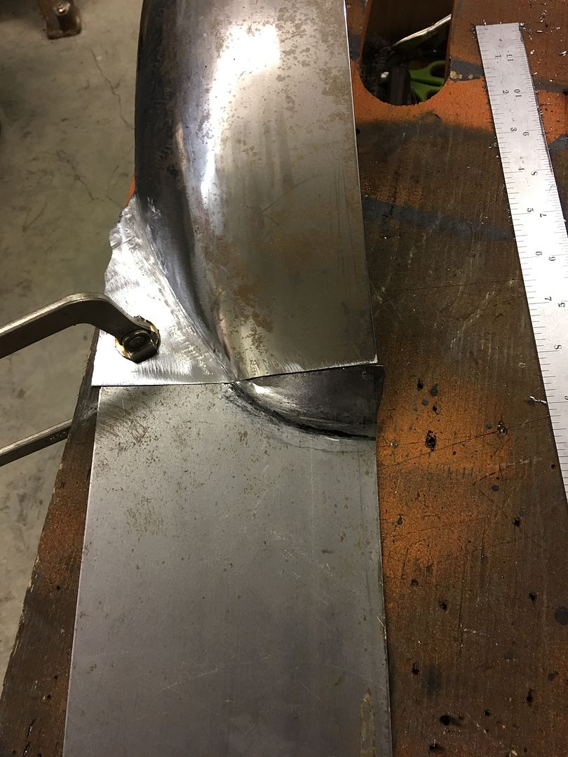
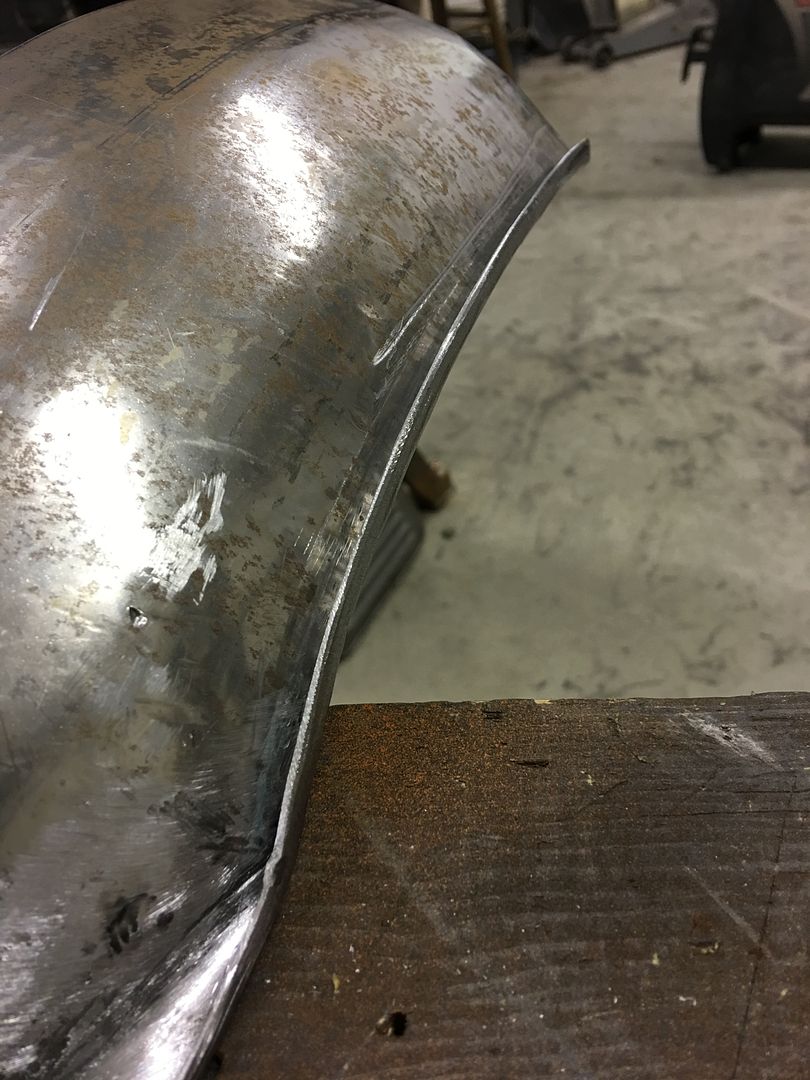
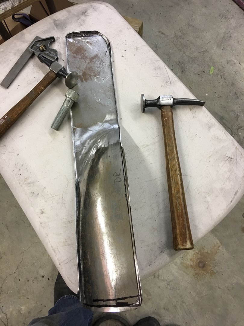
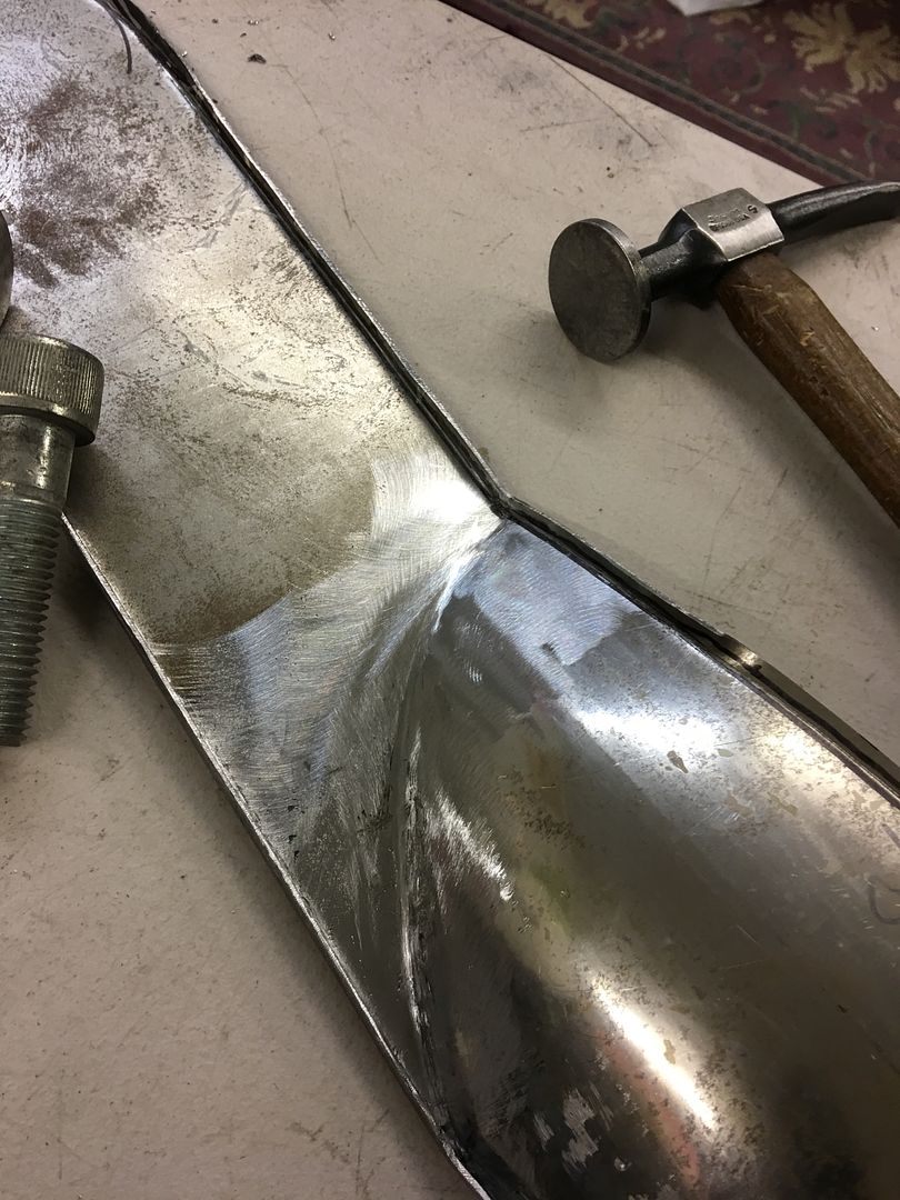
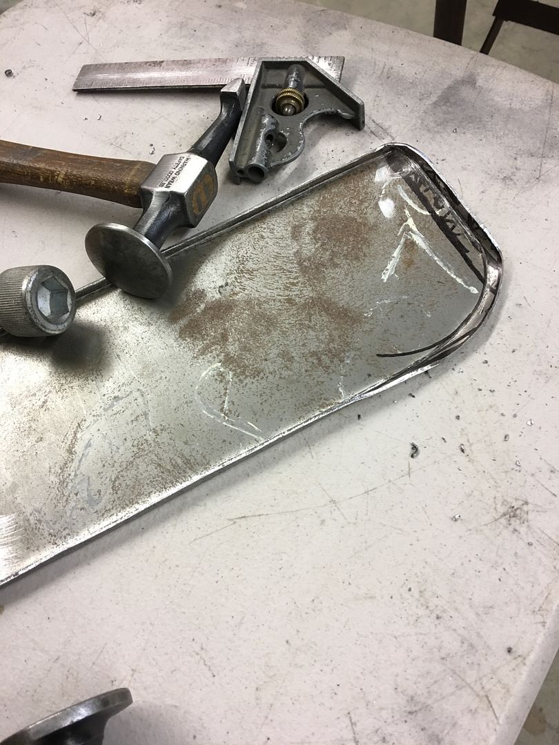
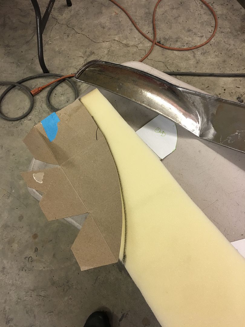
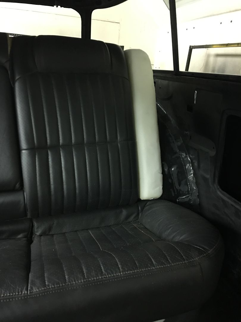
Then the rear corners needed relieving for the wheel tubs.....


IMG_2619.jpg


IMG_2621.jpg


IMG_2622.jpg


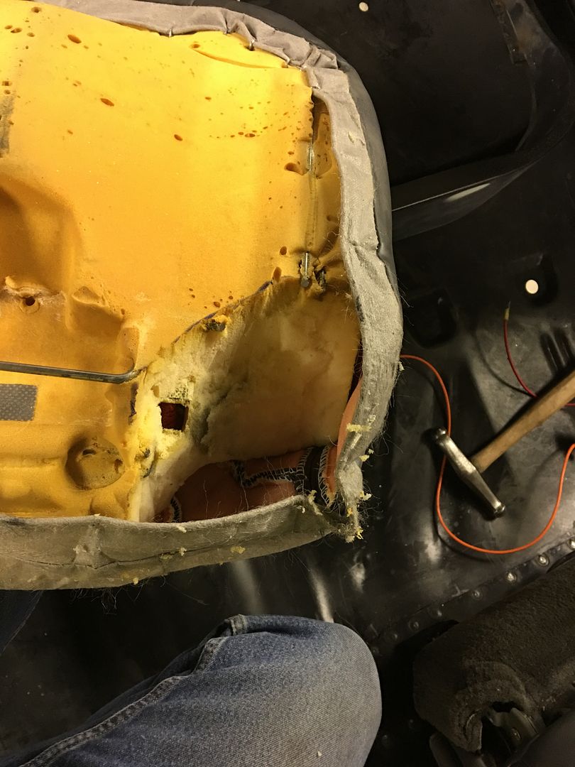
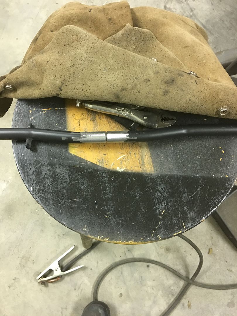
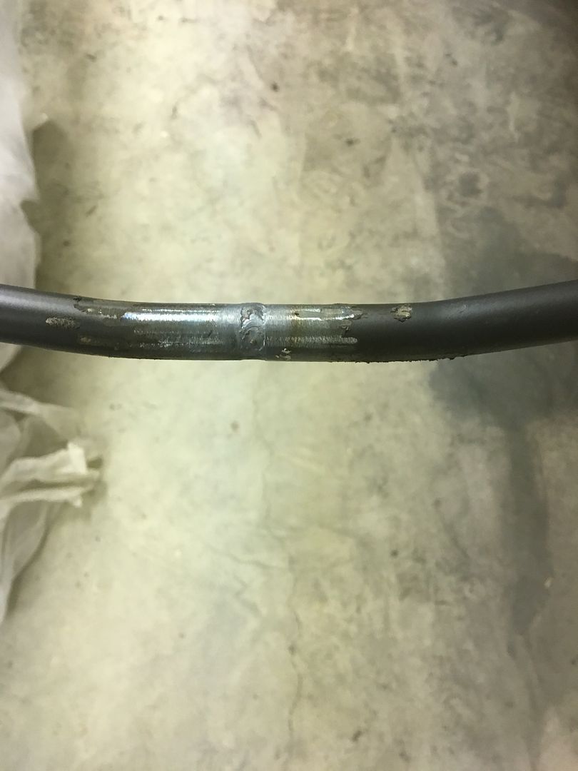
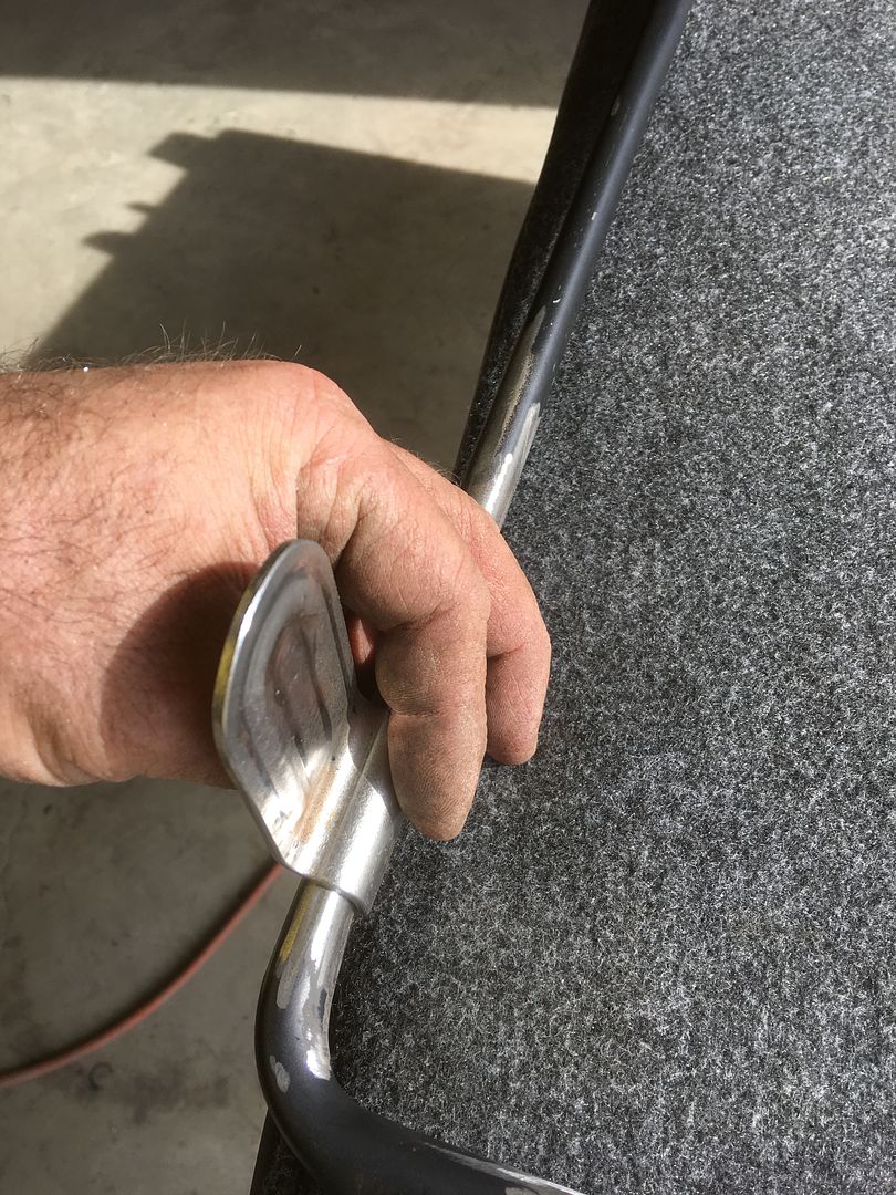
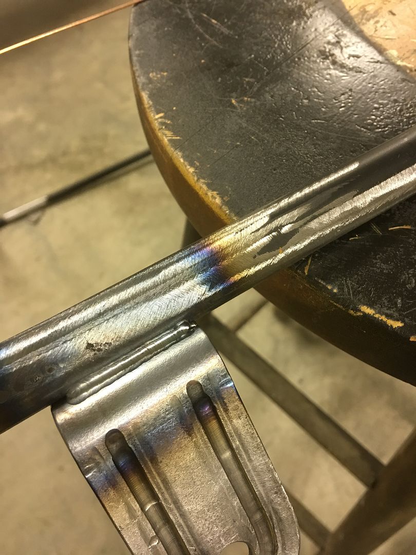
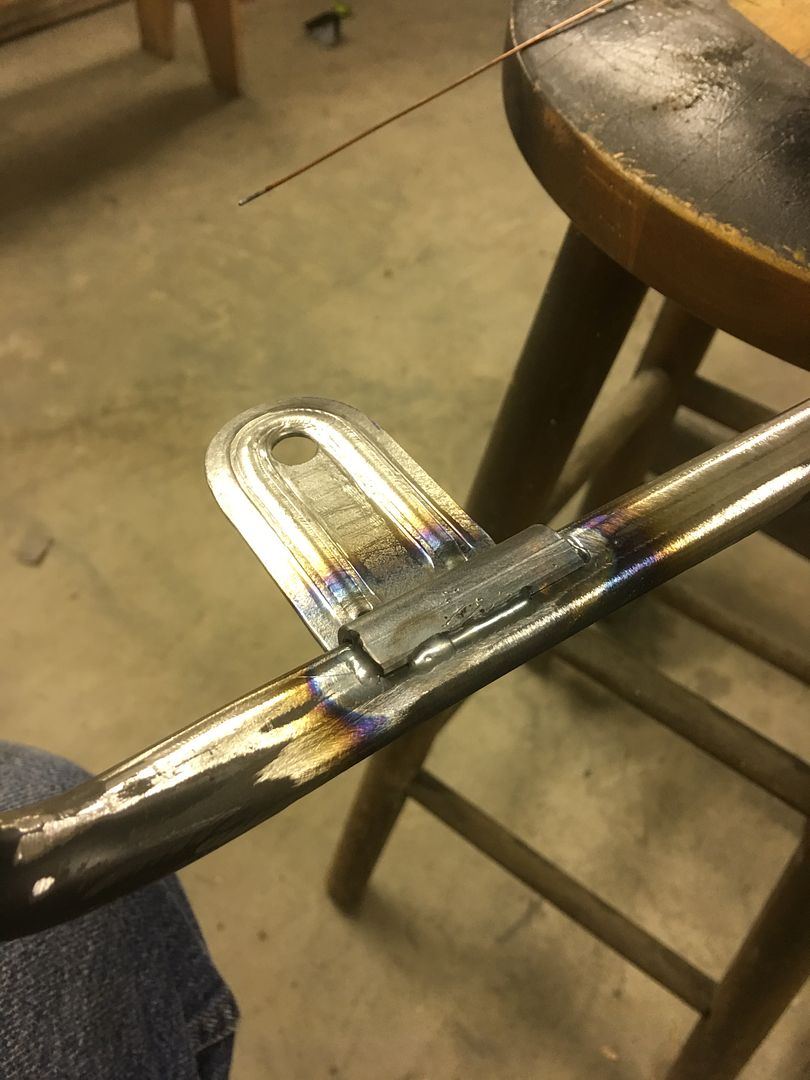
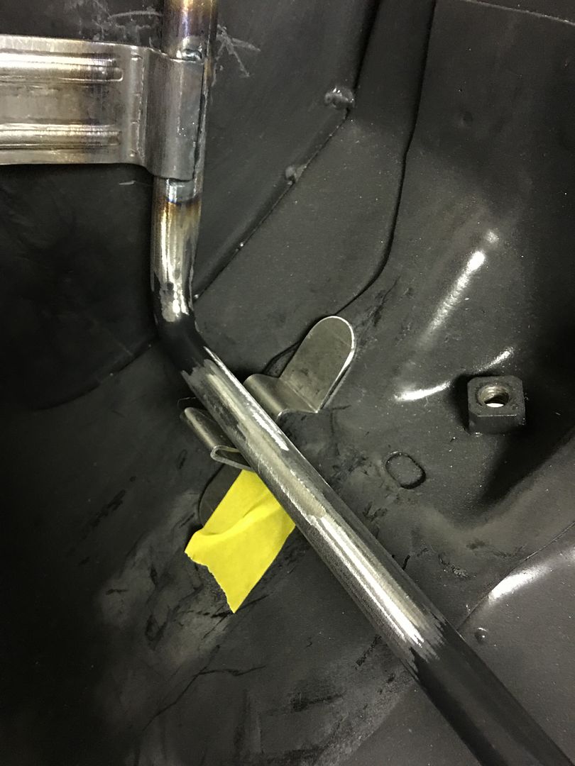
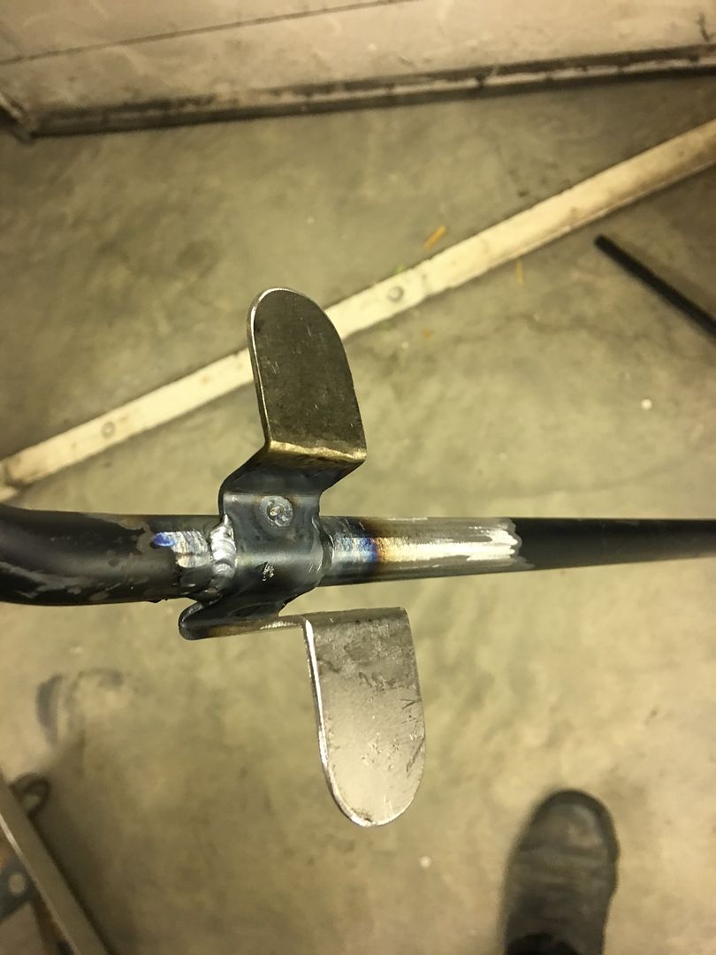
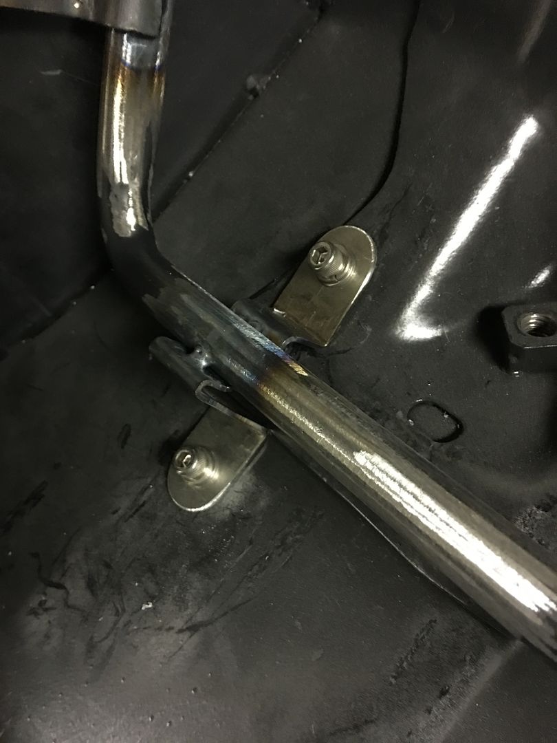
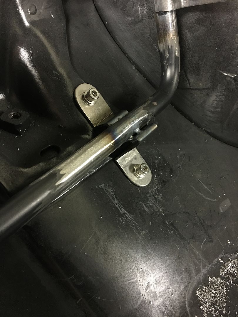
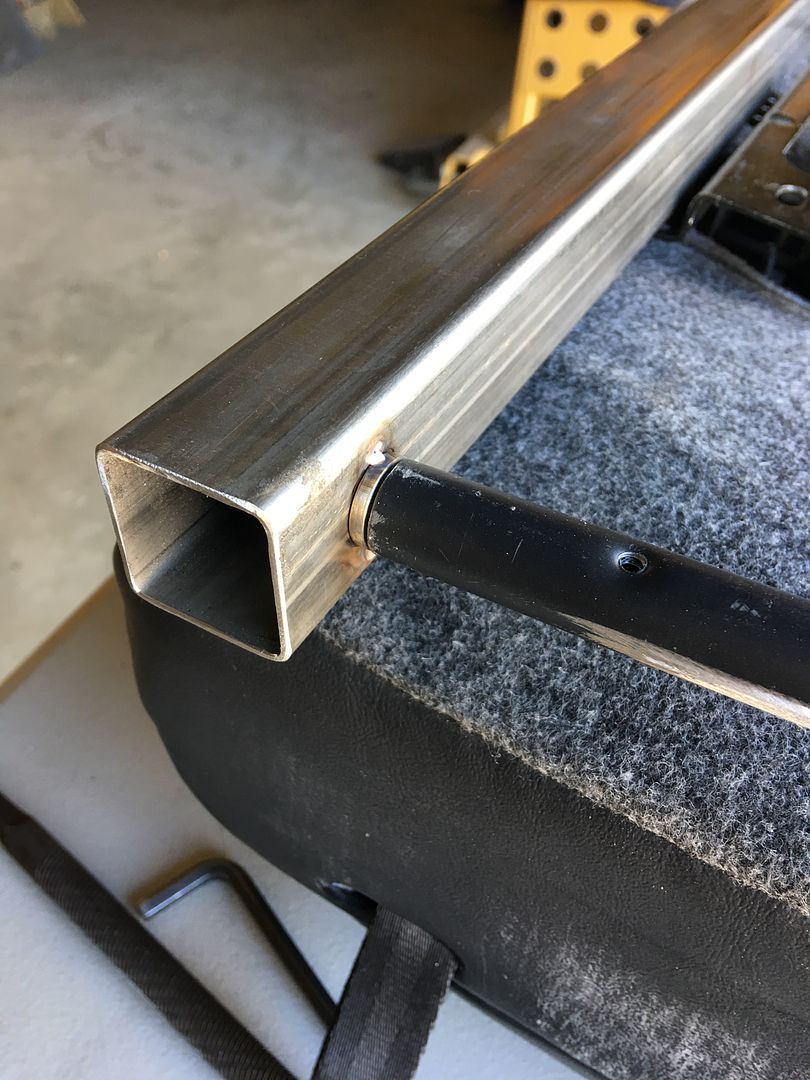
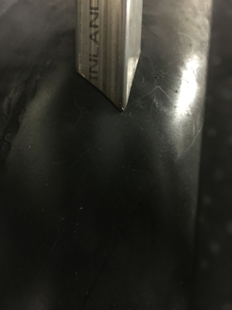
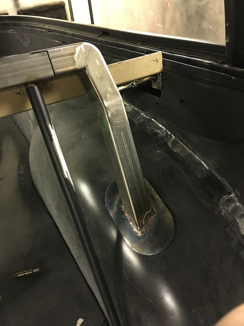
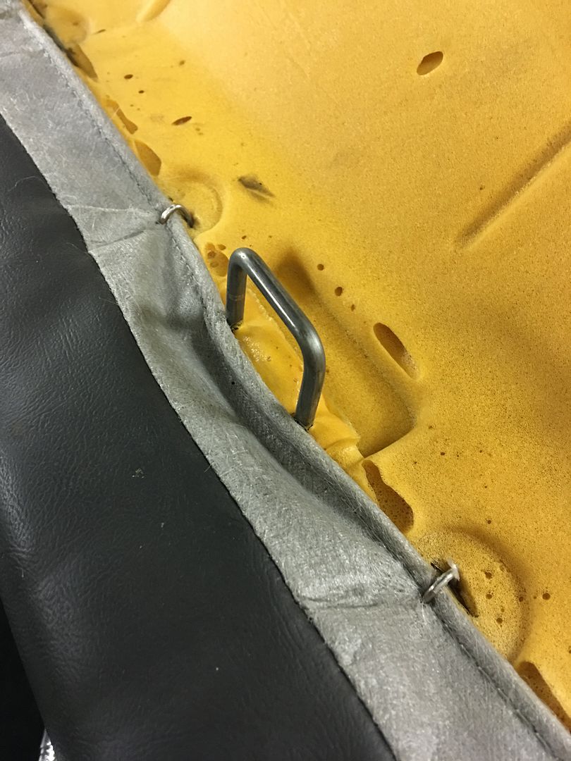
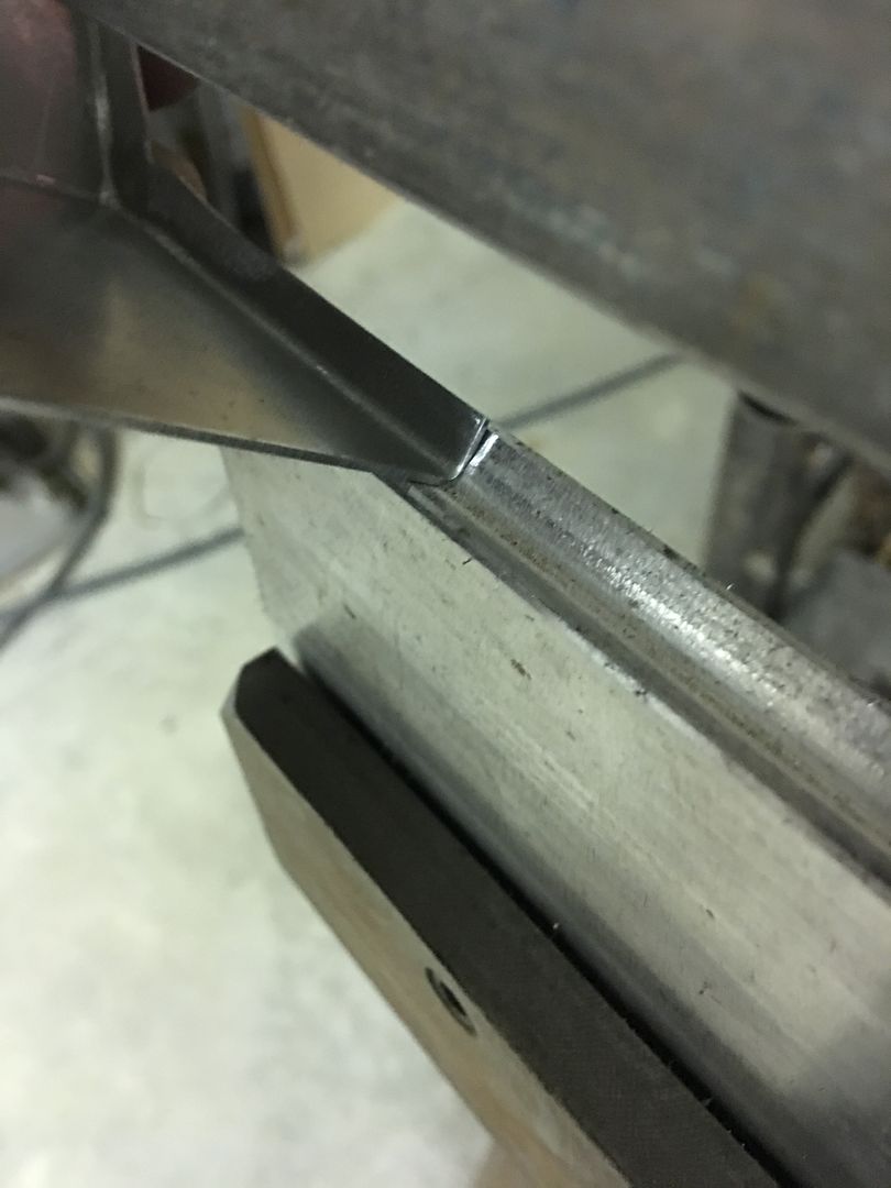
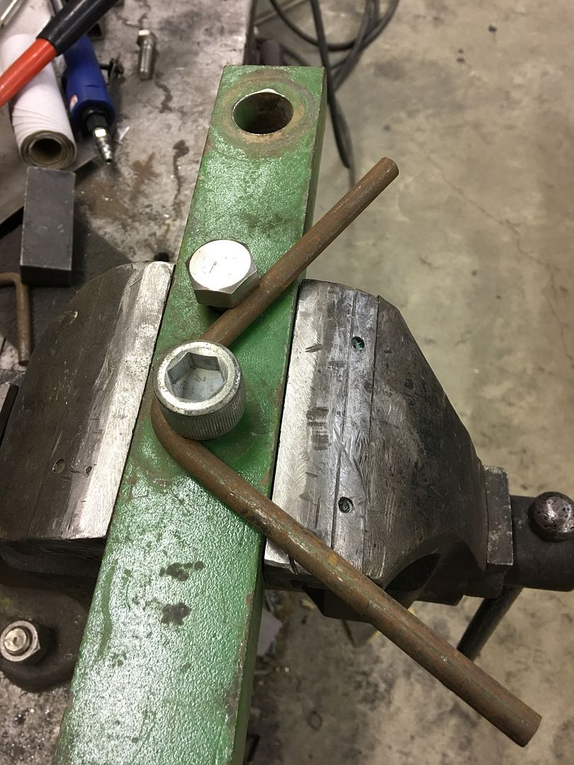
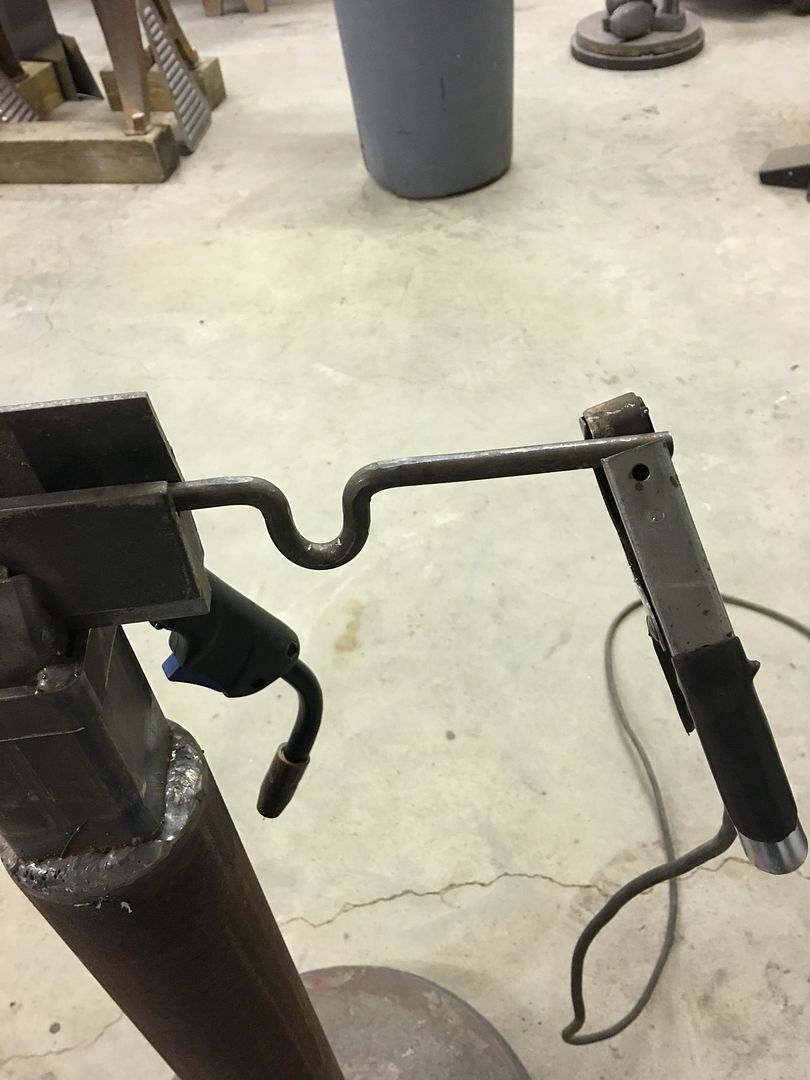
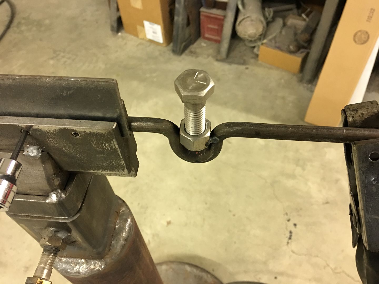
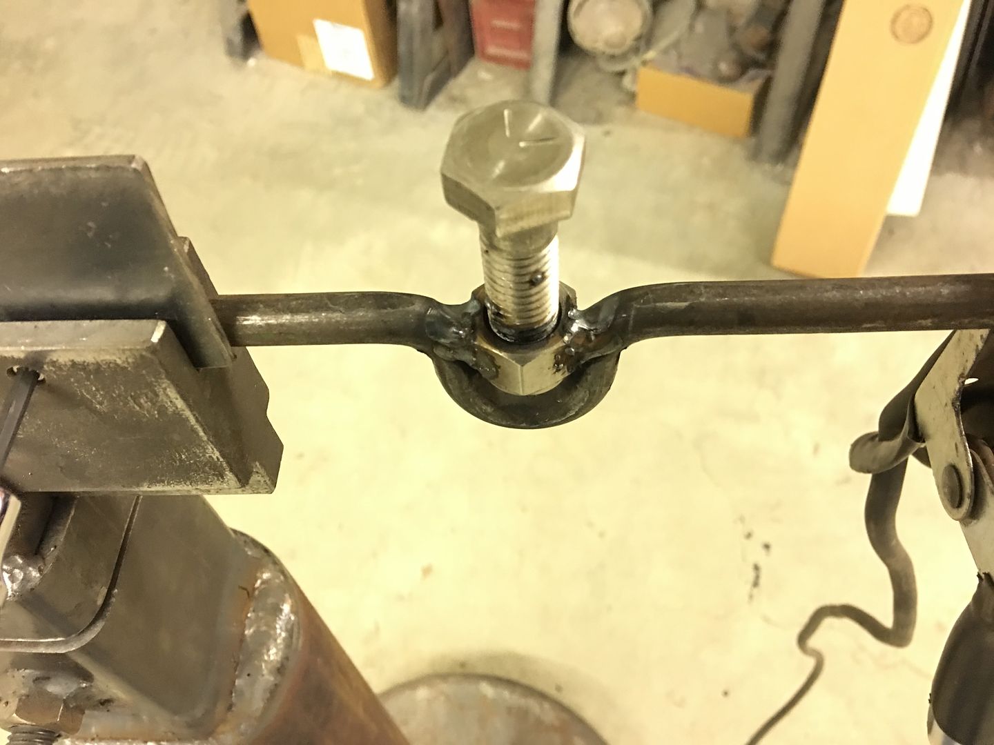
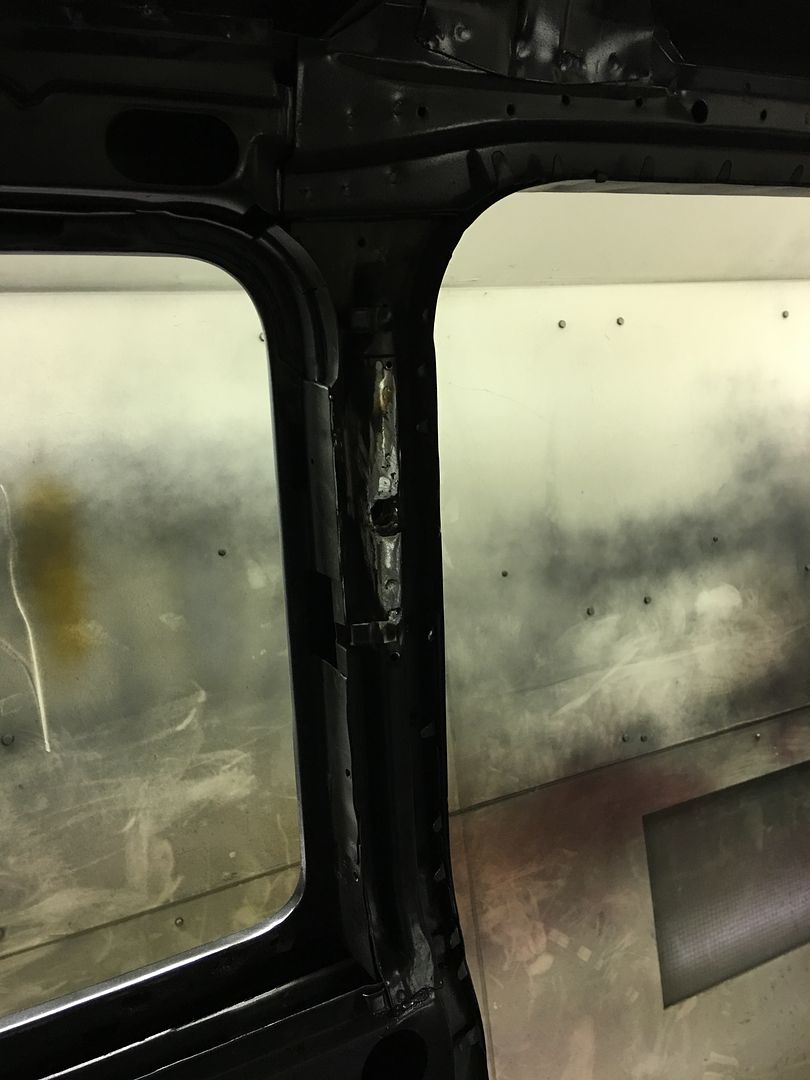
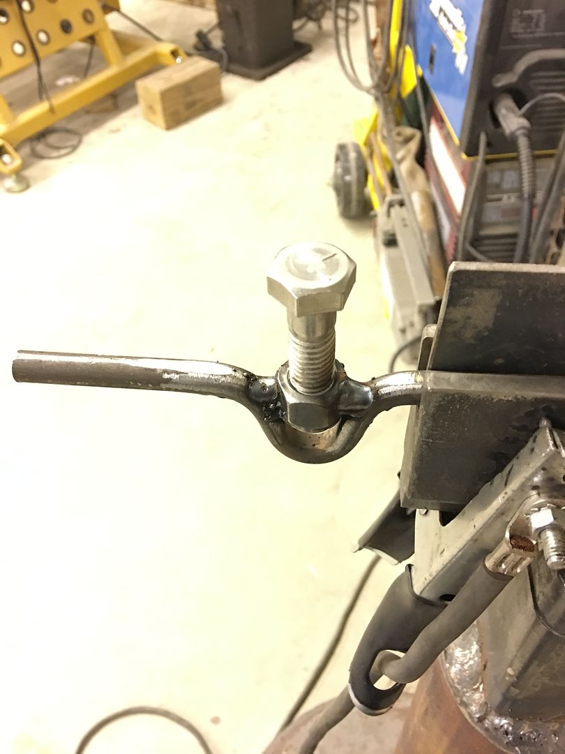
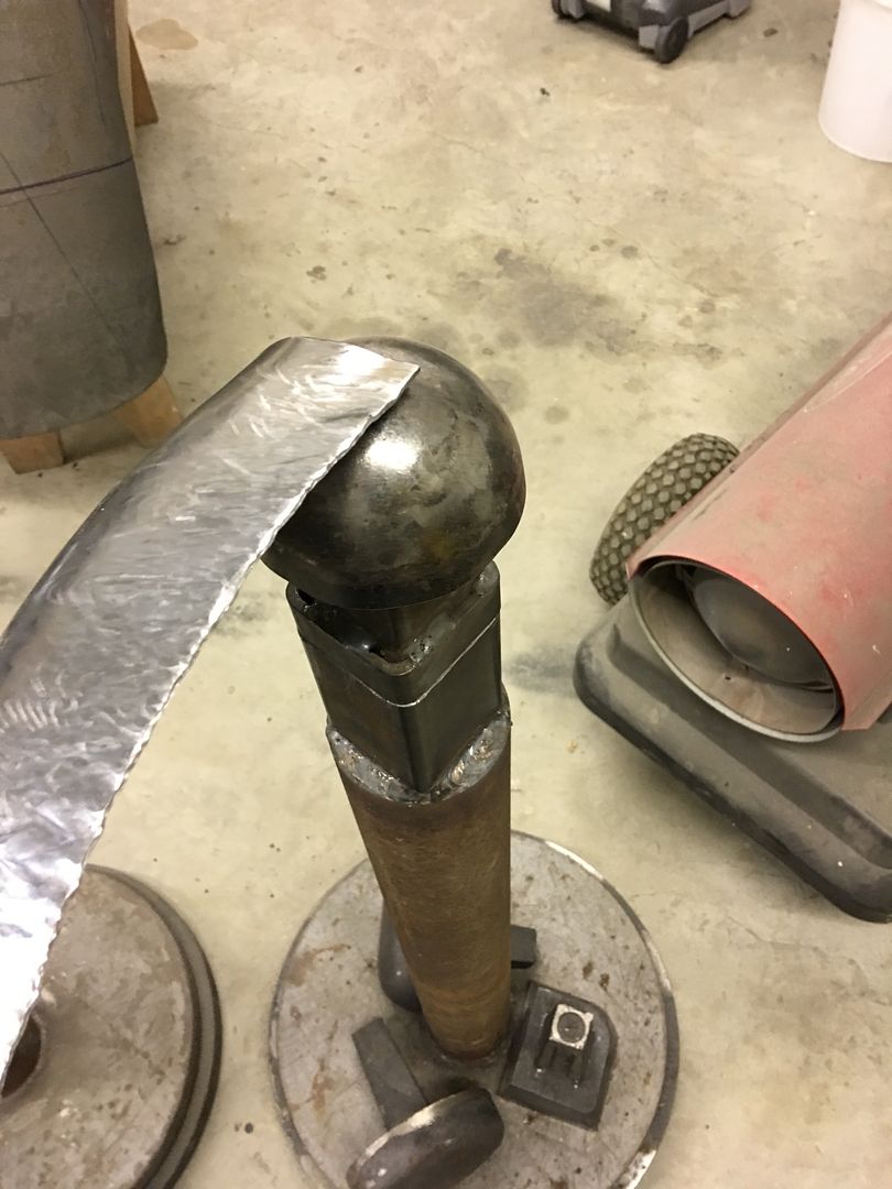
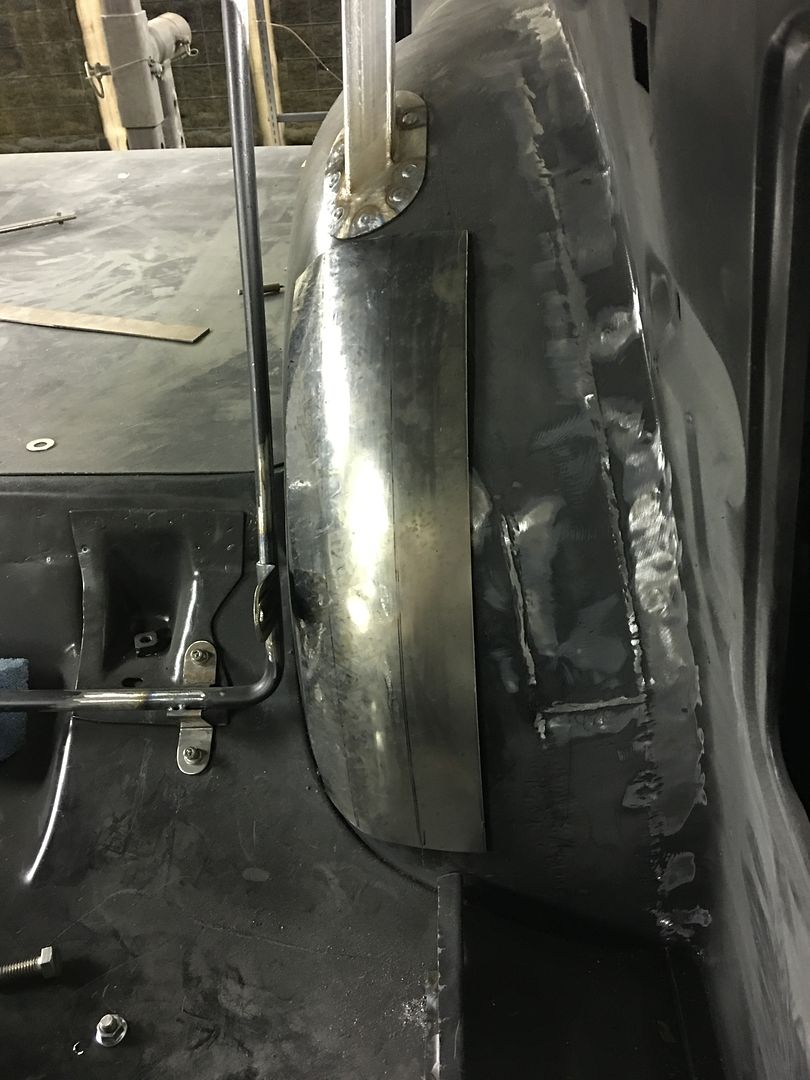
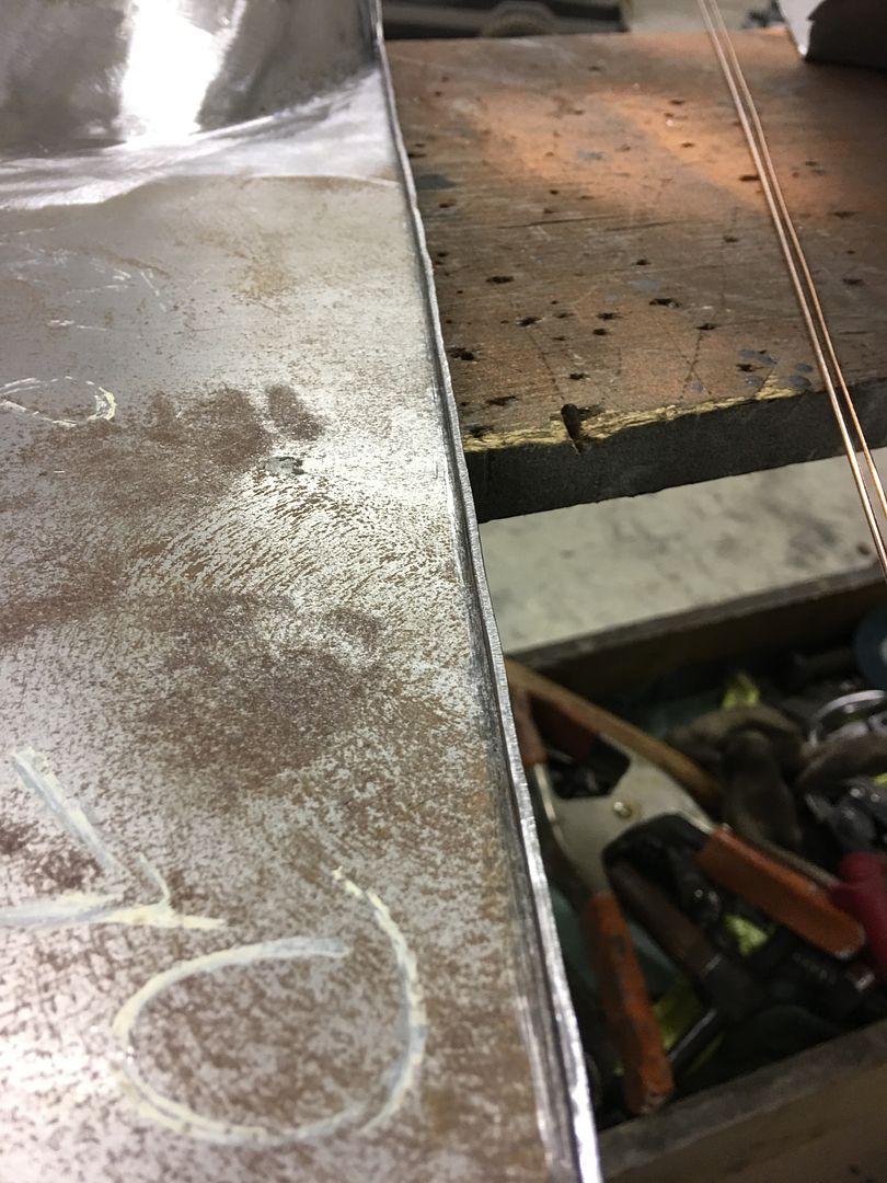
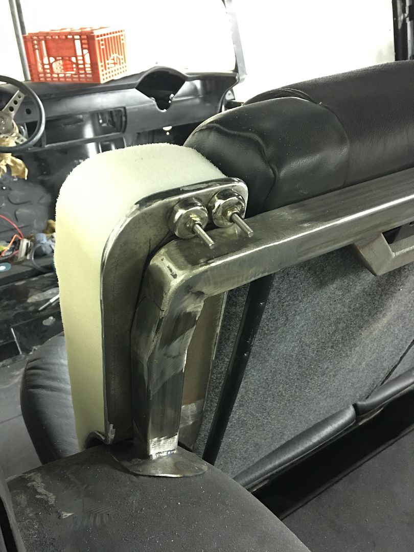
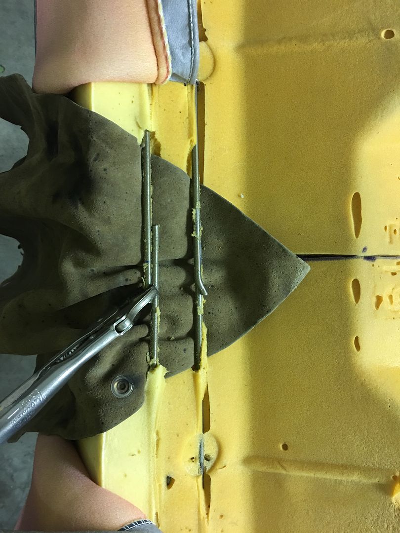
Some 3/16 diameter stainless rod was used to reconnect the pieces in the new rear corners


IMG_2623.jpg


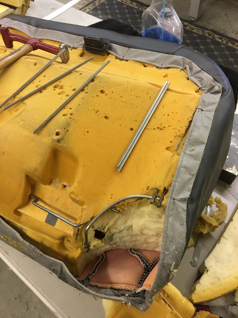
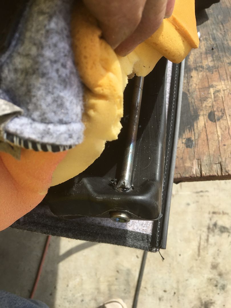
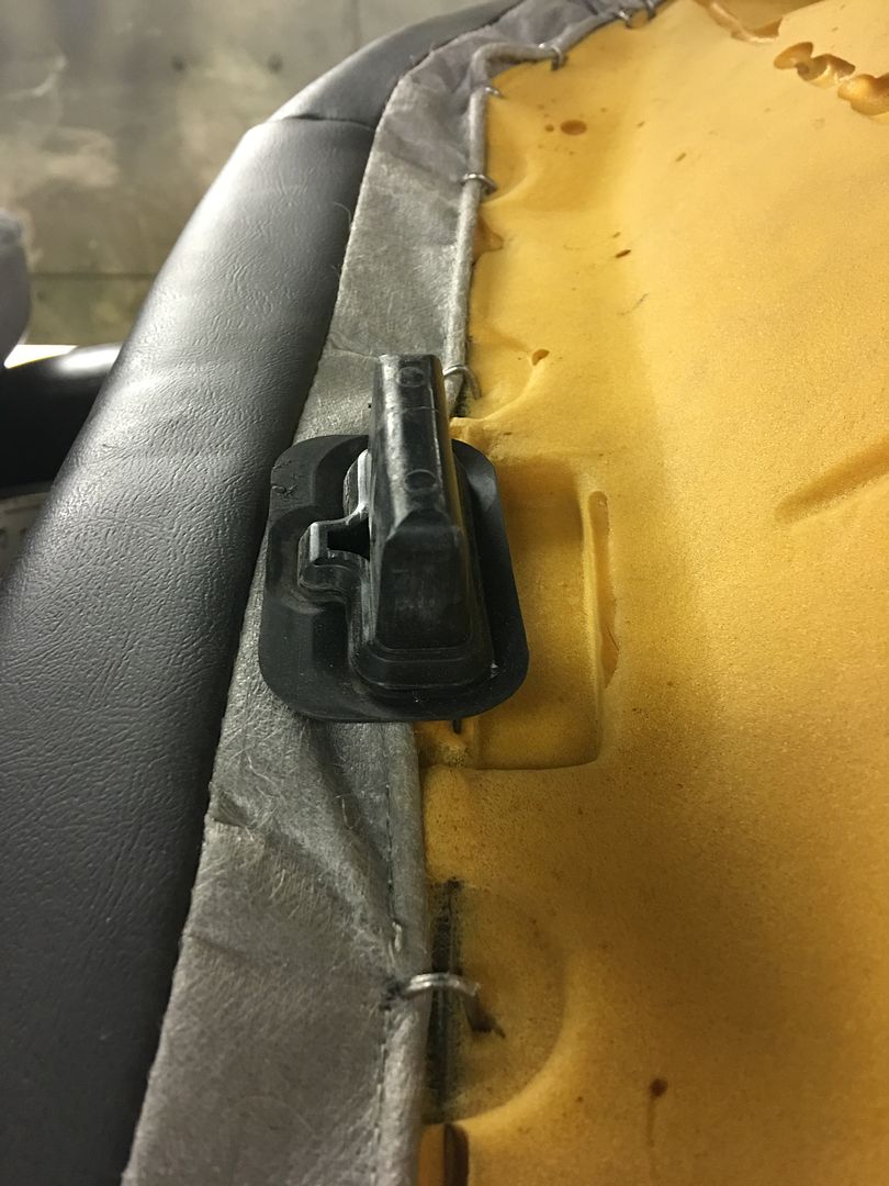
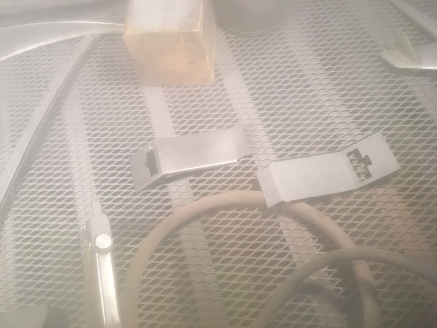
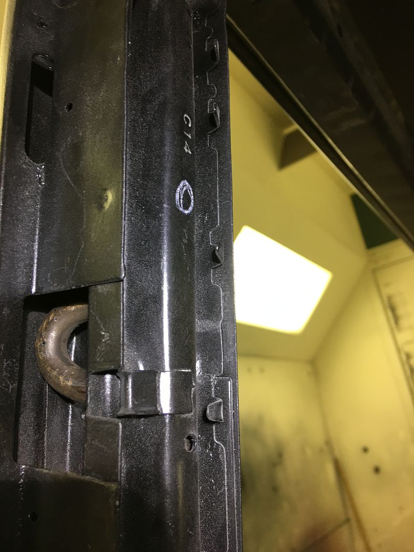
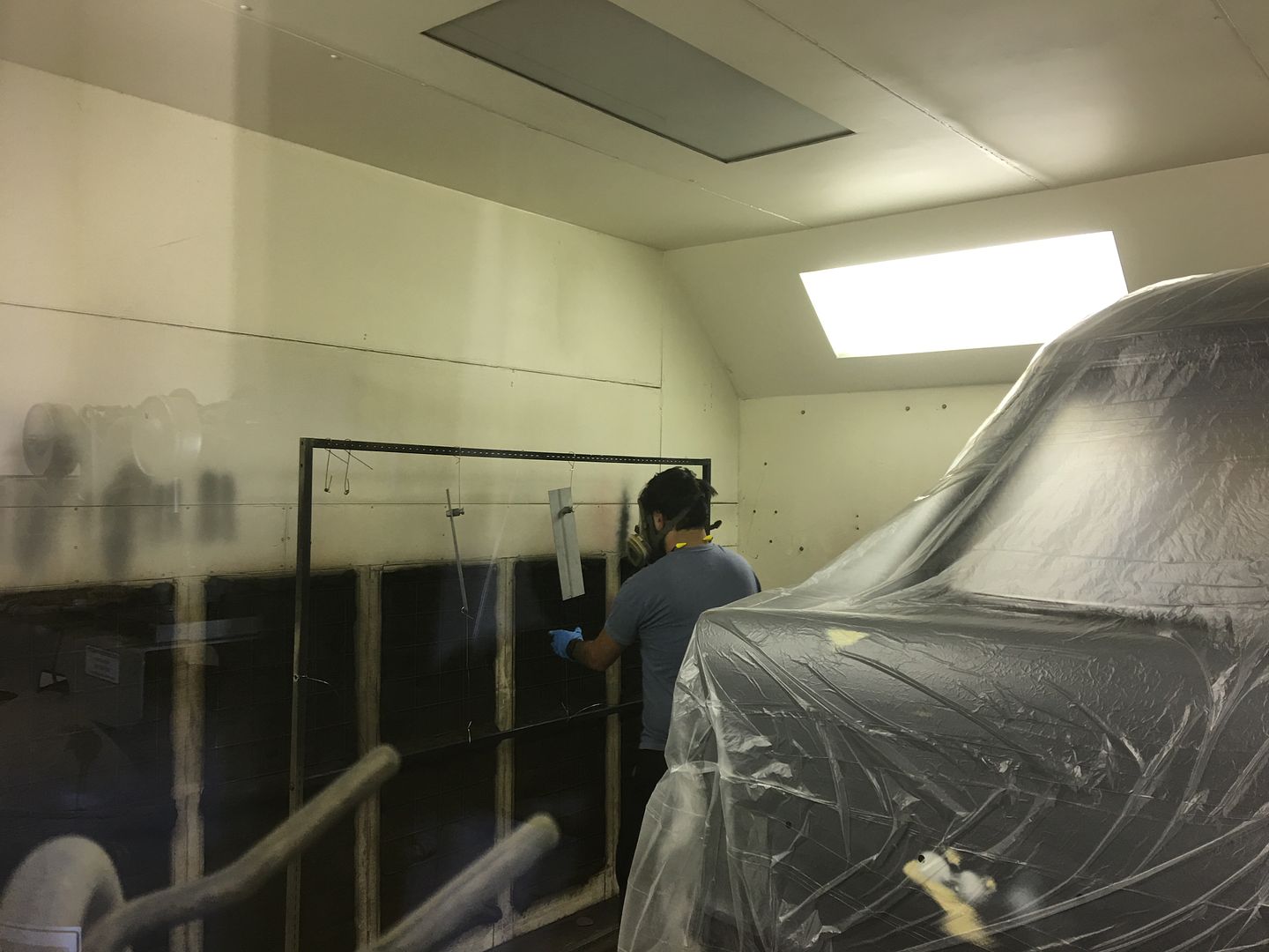
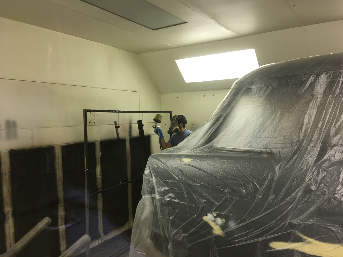
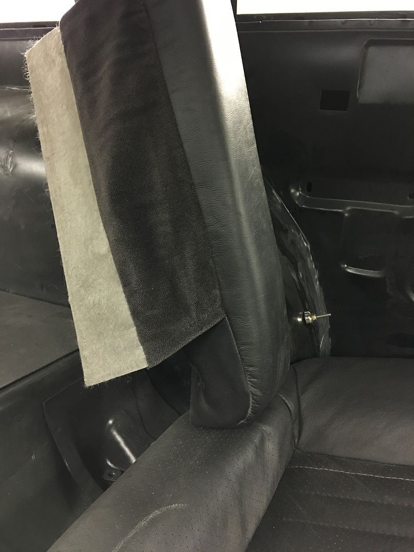
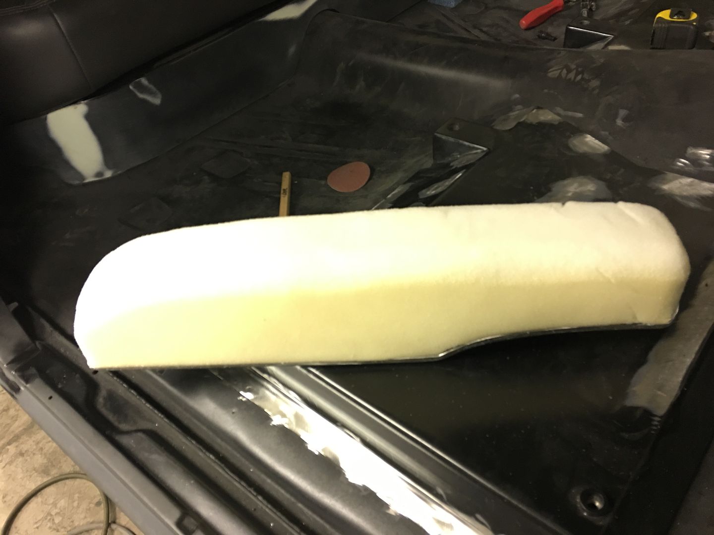
Some fire prevention for the foam..


IMG_2627.jpg


IMG_2630.jpg


IMG_2629.jpg


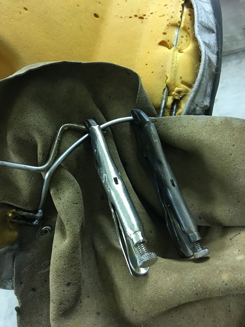
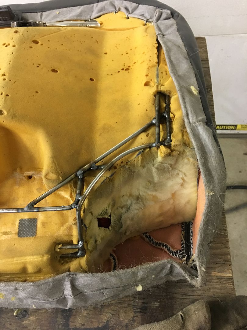
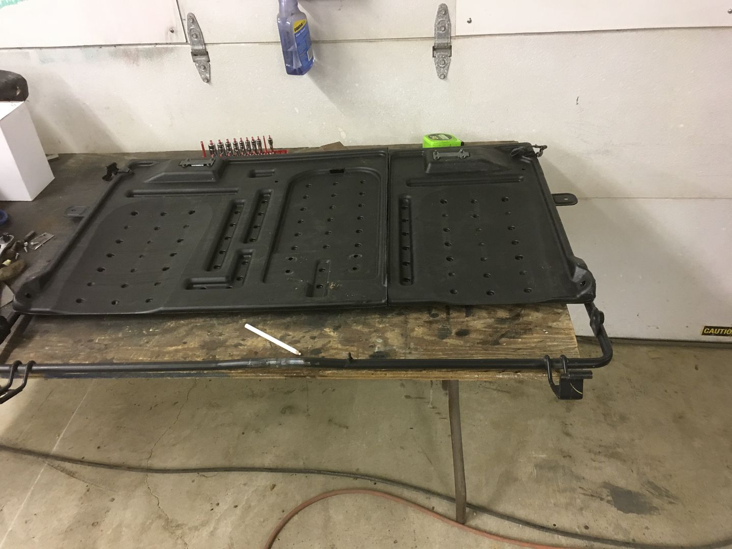
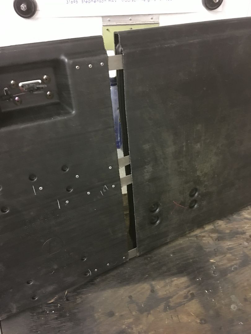
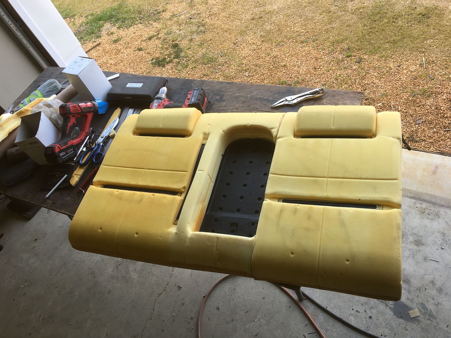
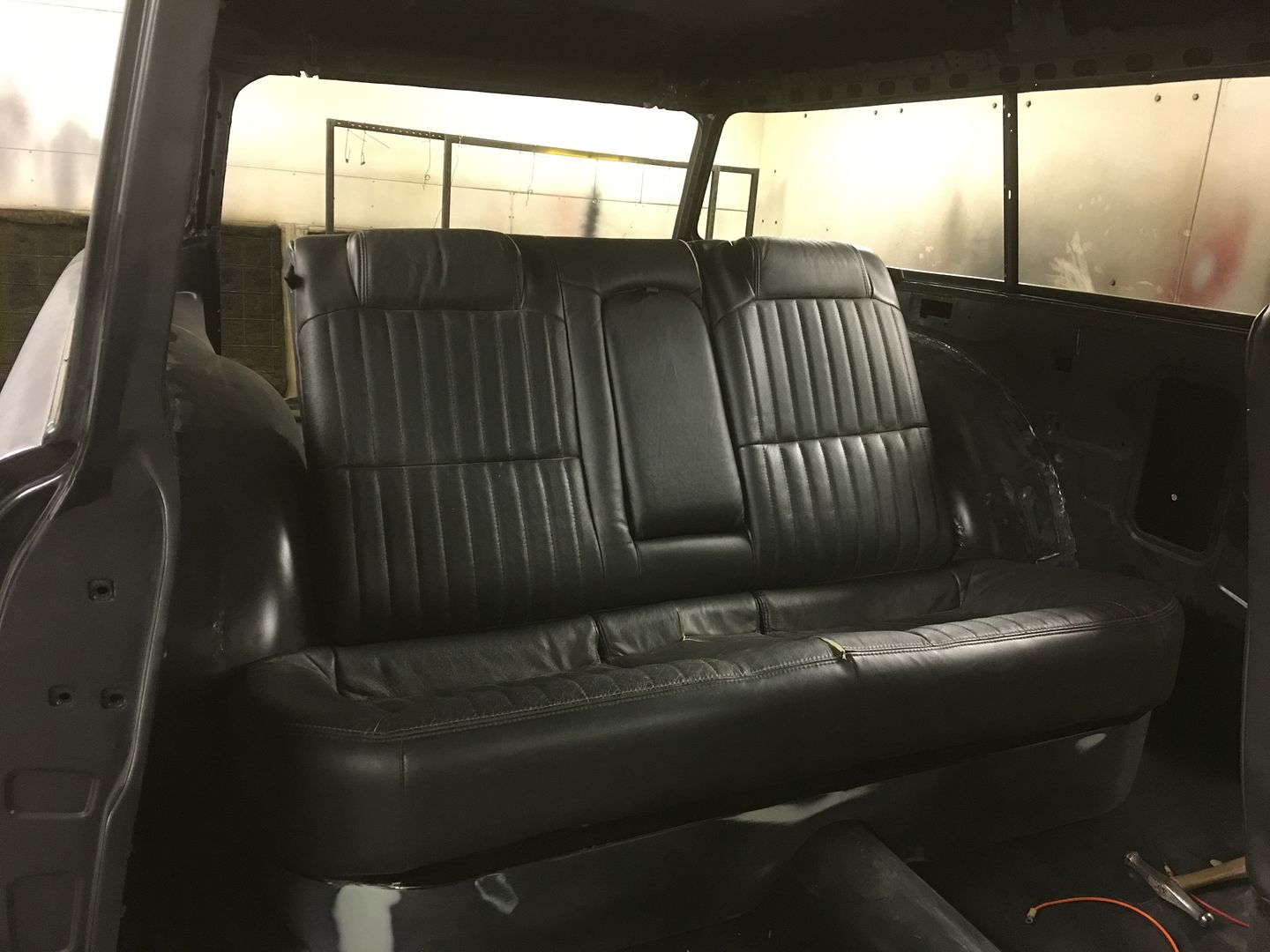
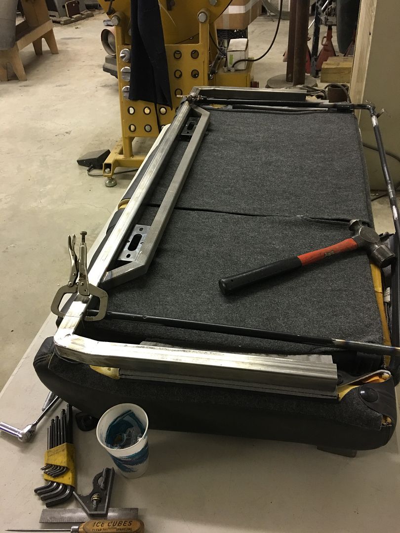
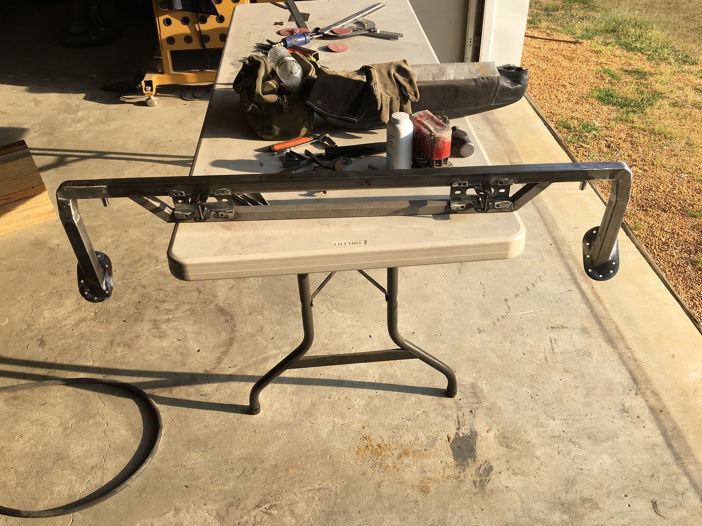
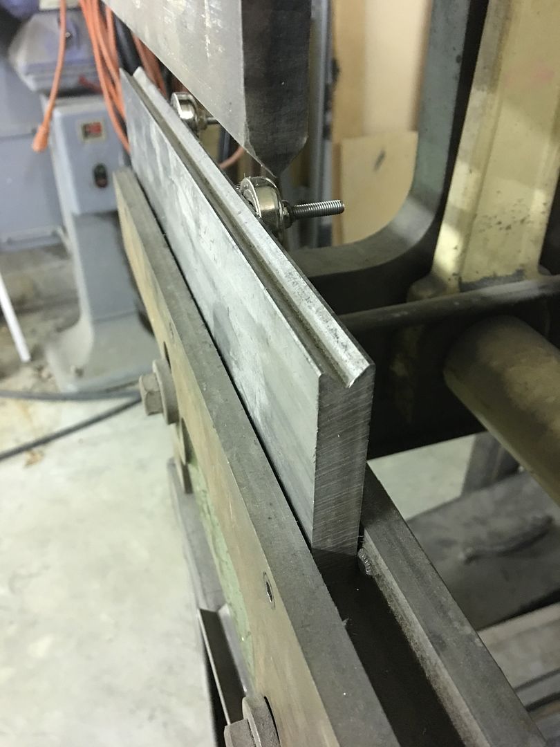
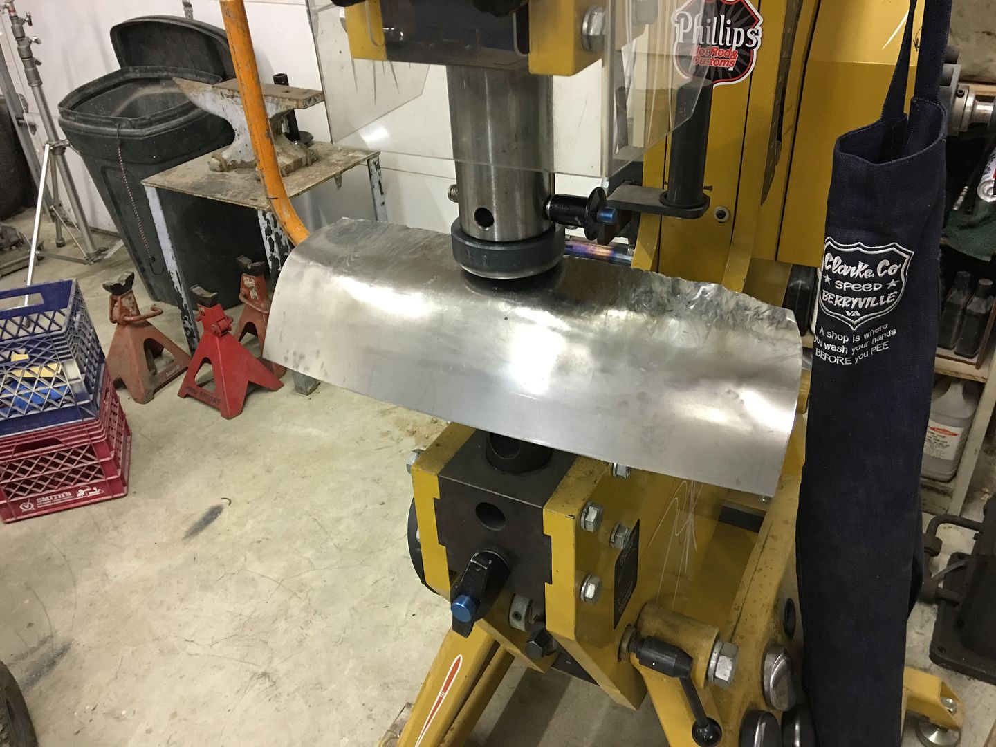
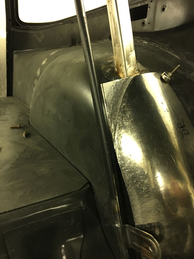
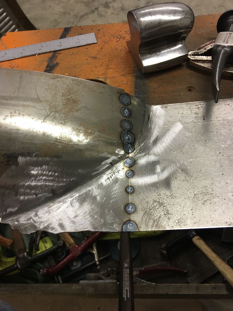
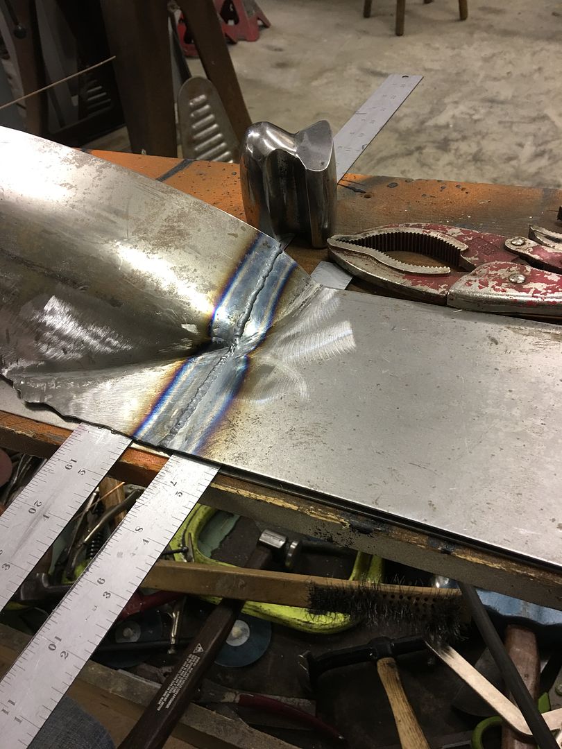
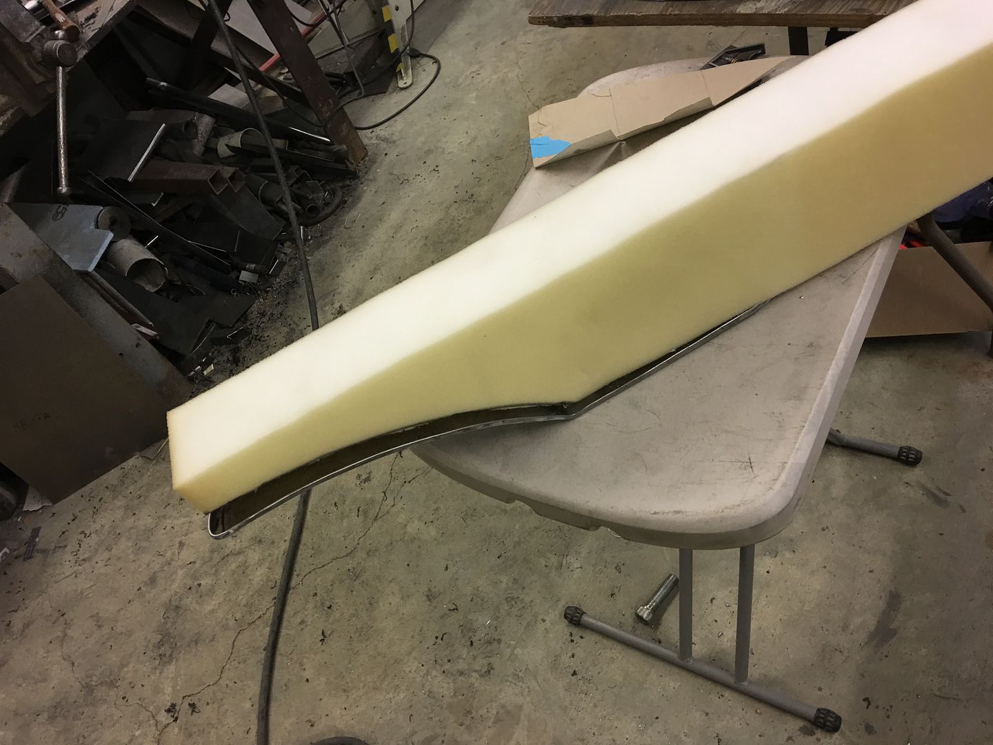
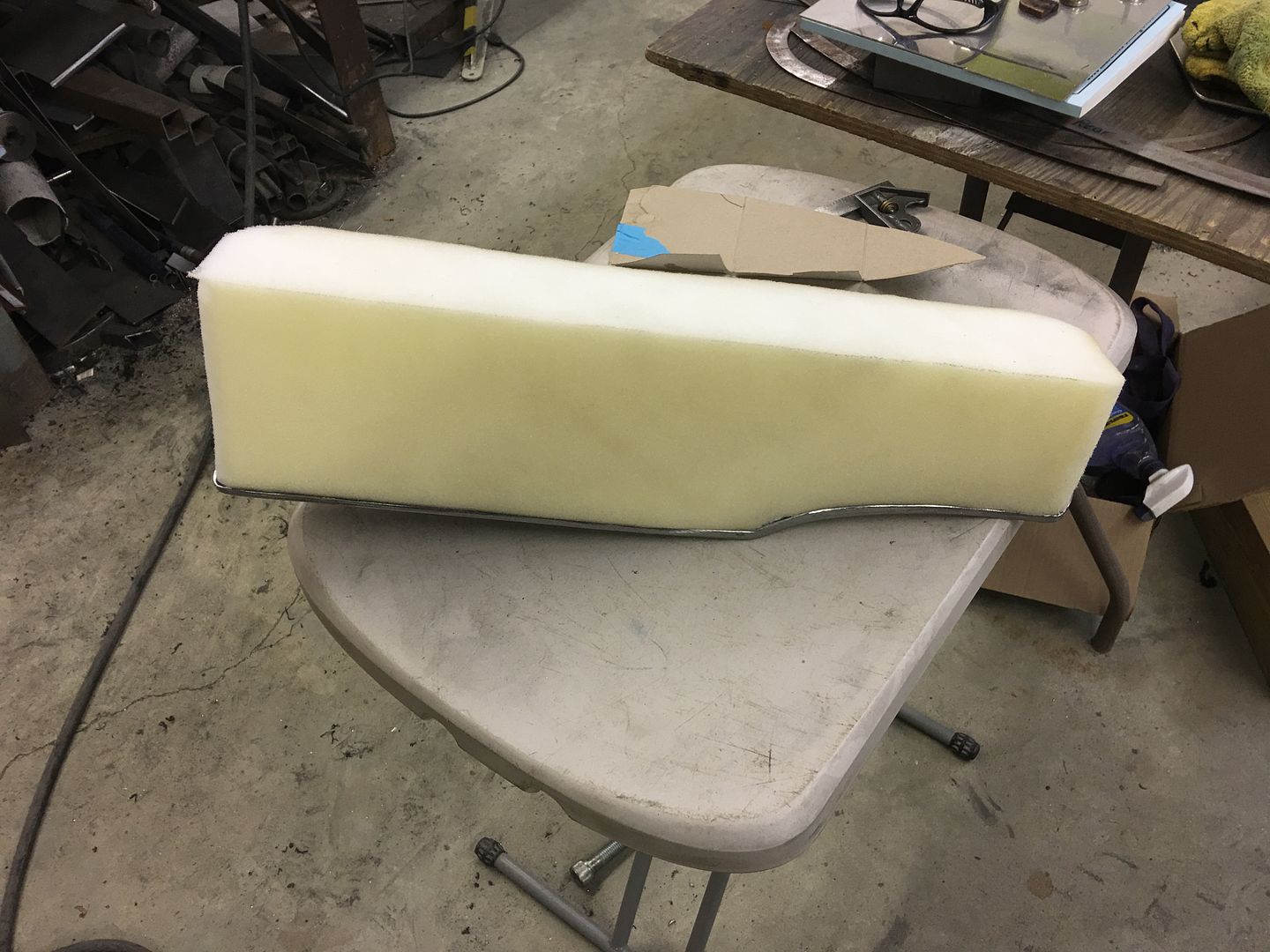
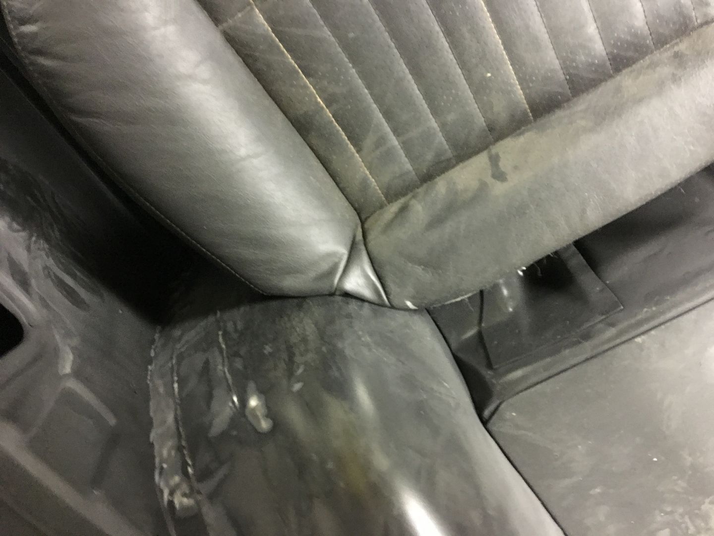
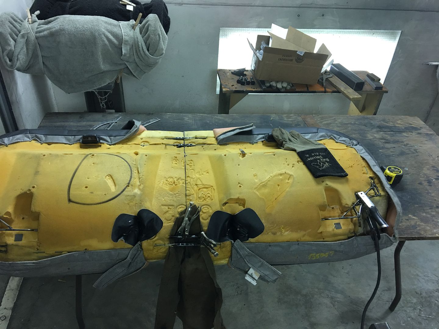
With both sides fitting individually, time to join our sides back together...


IMG_2631.jpg


IMG_2633.jpg


Video of the surgery results....


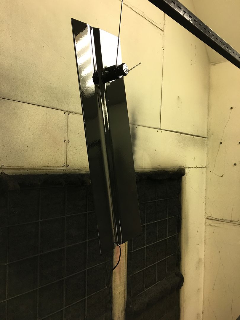
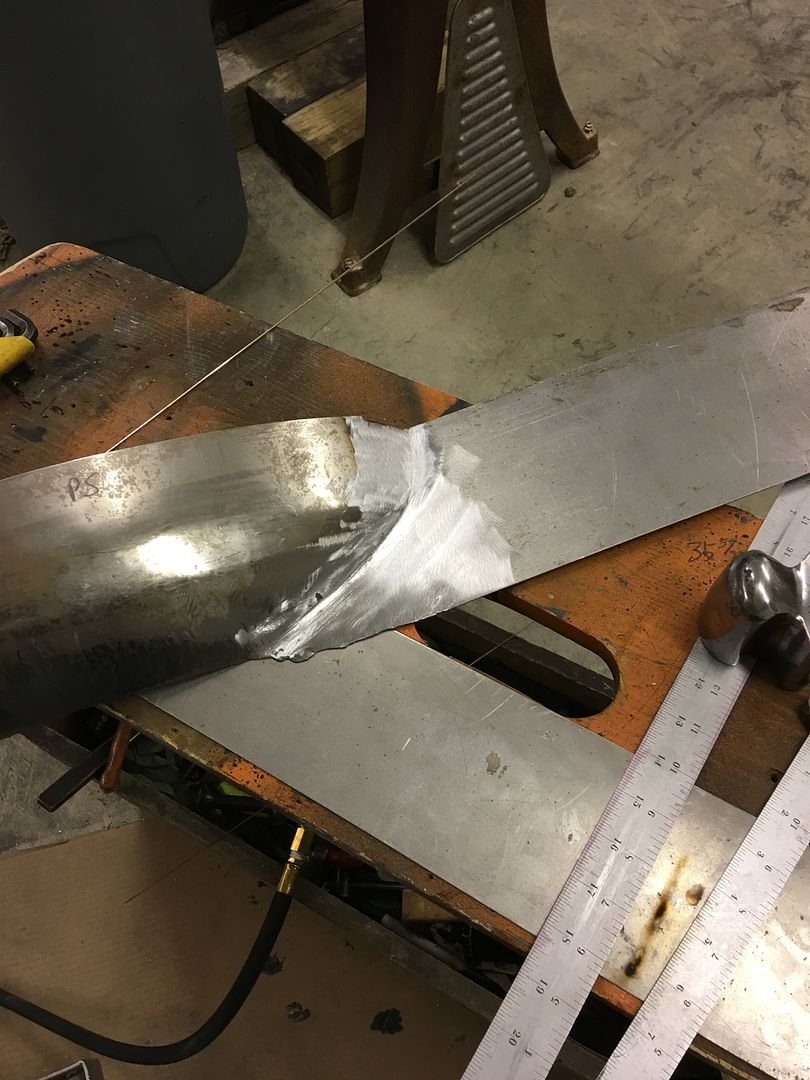
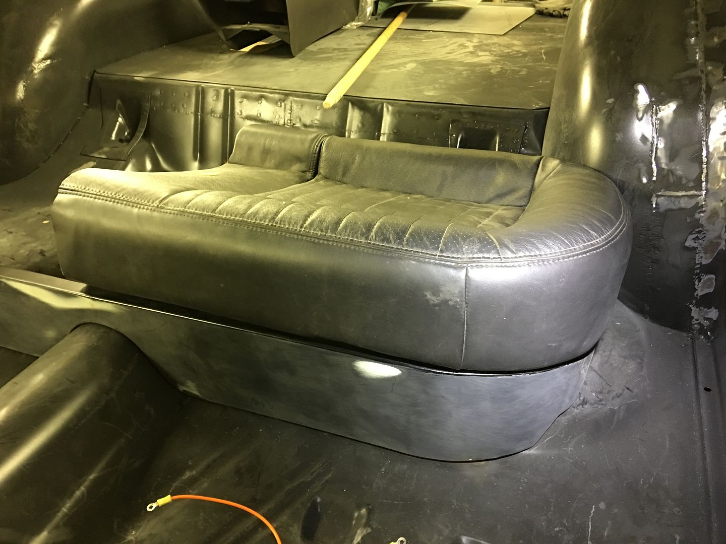
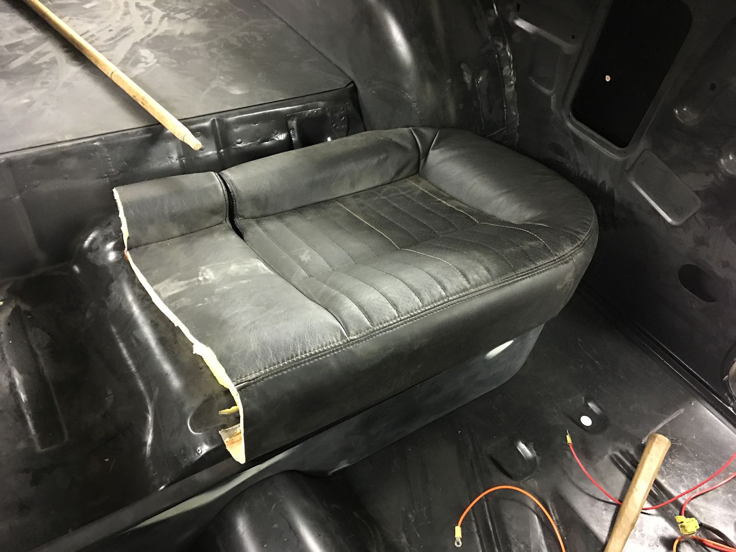
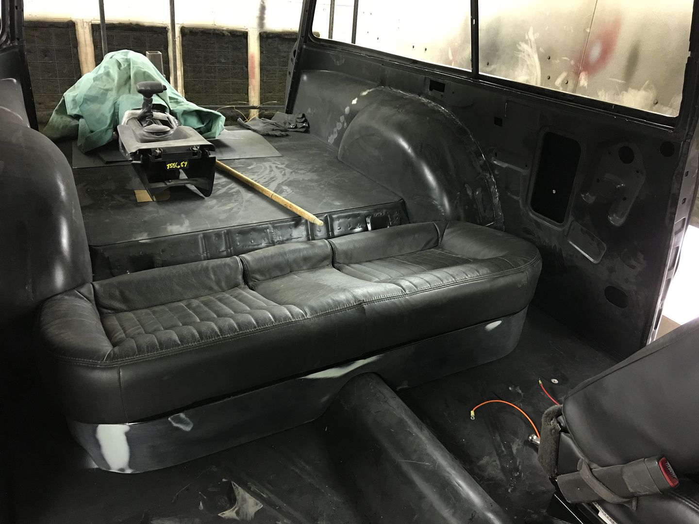
With the overlap of material trimmed, this part is looking pretty good!


IMG_2641.jpg
 
With the 55's rear seat bottom narrowed to fit the wheel tubs.....


IMG_2641.jpg


....time to do the same for the seat back. First to blow it apart....


IMG_2713.jpg


This had a multiple fold down, arm rest in the middle, non 55 looking arrangement. The arm rest will be first to go, and we'll attach the fold down sections together..


The frame is sectioned in the middle, a tube driven inside, and TIG welded around the perimeter..


IMG_2714.jpg


IMG_2715.jpg


Then the seat innards are trimmed accordingly to make a one piece back..


IMG_2716.jpg


IMG_2718.jpg


Then some 14 gauge strips are cut out to join the two sections together..


IMG_2719.jpg


IMG_2720.jpg


IMG_2721.jpg


IMG_2724.jpg


IMG_2725.jpg


IMG_2727.jpg


IMG_2726.jpg


IMG_2728.jpg


IMG_2730.jpg


That should work, tomorrow we'll work on the new pivot brackets..
 
In removing the section of foam on the seat back we find the cushion has a wire around the arm rest void. As we are removing the arm rest altogether (when it gets reupholstered) we removed the wire..


IMG_2732.jpg


IMG_2733.jpg


IMG_2734.jpg


IMG_2736.jpg


The previous pivot for the seats had a tapered pin hex bolt that secured into a hex nut that was welded onto the pivot bracket, which can be seen here:


IMG_2717.jpg


Due to our width constraints, we need to remove all that excess hardware.. So we chose to put the "securing nut" inside the seat, and use a simple pan head allen screw through the 12 gauge bracket.. Here's our Pivot "axle" inside the seat back..


IMG_2742.jpg


IMG_2743.jpg


Here's the test fit of our 12 gauge steel pivot bracket. Radius was used on the bends to match the tube. The tube was originally round, and the side uprights were flattened out using the MH19 hammer to buy us some more clearance between wheel tubs..


IMG_2744.jpg


The bead shown on the bracket was done on the Lennox Nibbler.
This should give us a bit of clearance on the edges to help prevent binding of the upholstery.

IMG_2748.jpg


Bead turned out pretty well for 12 gauge steel! Some TIG welding to put the parts together:


IMG_2749.jpg


IMG_2750.jpg


IMG_2752.jpg


Video of it in operation:


One part down, next we'll tackle the brackets to the floor.
 
Back in the shop this evening, time to make some bolting brackets to hold the seat back frame to the floor..

IMG_2799.jpg


Locating...


IMG_2802.jpg


IMG_2804.jpg


Brackets TIG welded on....


IMG_2808.jpg


This shows it in place, we have about 1/4" clearance at the tight spots....


The cleco's were removed and 1/4-20 AVK rivet nuts installed in the floor... Missed that picture...


IMG_2817.jpg


IMG_2818.jpg


Next will be the top support....
 
Last edited:
Now for the top of the seat frame... We started with some 3/8-16 standoffs that are 5/8 diameter, and turn them to 1/2 diameter to fit inside the seat frame tube...


IMG_2826.jpg


IMG_2827.jpg


IMG_2828.jpg


IMG_2830.jpg


Then holes are drilled in some 1.25 square tubing...


IMG_2832.jpg


IMG_2833.jpg


Tacked in place and a nut used for added insurance...


IMG_2837.jpg


IMG_2836.jpg


IMG_2839.jpg


Seat latches plug welded in place...


IMG_2844.jpg


Side pieces formed....


IMG_2842.jpg


IMG_2856.jpg


IMG_2847.jpg


IMG_2848.jpg


IMG_2849.jpg


The side pieces will be trimmed, fitted, and welded to the wheel well...


IMG_2855.jpg
 
Interior work like that is dam impressive. That's one part I haven't gotten into but would like to do especally making a custom dash.

Nice work and thanks for taking the time to post the progress.
 
Thanks!


More work on the seat back bracket... Trimming the side pieces to match the wheel well...


IMG_2860.jpg


Adding welding flange, hammered out of 16 gauge steel..


IMG_2864.jpg


IMG_2866.jpg


Test drive....


https://www.youtube.com/watch?v=mpFl01yHvKw


Used the Roper Whitney hand punch to make our plug weld holes..


IMG_2871.jpg


IMG_2872.jpg


IMG_2873.jpg


IMG_2875.jpg


Next we'll close off the back area to contain the amp and bass speaker.
 
Here are the factory seat retainers to hold the seat bottom in place.


IMG_3149.jpg


IMG_3150.jpg


Time for some brackets to hold the retainers. Cut out some 19 gauge...


IMG_3152.jpg


Drilled some holes for an inside radius, and trimmed the corners for the floor pan flange..


IMG_3154.jpg


Now to fold some flanges on the sides for strength, using the Diacro press brake and a 1/2" thick lower die. By adding some rare earth magnets to the back side to serve as a back stop, we get a perfect 1/4" flange...


IMG_3155.jpg


IMG_3156.jpg


Then some back and forth between the Erco kick shrinker and the press brake with a narrow die inside the folds.... and we have 45* bends on either end of our brackets...


IMG_3157.jpg


Test fit.... and trimming the retainer hole...


IMG_3160.jpg


IMG_3161.jpg


IMG_3162.jpg


IMG_3163.jpg


IMG_3167.jpg


IMG_3169.jpg
 
Thanks for the comments guys!


Had our new apprentice started today, while I cut out the hole in the second seat bracket, Mike got started on punching and drilling holes for plug welding the passenger bucket seat bracket...

IMG_3186.jpg


IMG_3187.jpg


IMG_3189.jpg


After I got the bracket hole cut out, E media blasted the brackets and added some SPI epoxy using a brush. We mainly wanted to get the bottom side well covered as it will be inaccessible once welded in place..

IMG_3190.jpg


IMG_3199.jpg


First coat...


IMG_3201.jpg


Two coats, that should hold us for under a seat...


IMG_3214.jpg


Meanwhile I got out the John Deere rod bender to see if we could make up some anchors for the shoulder belt..


IMG_3202.jpg


Bent with relief for a 1/2-13 lock nut..


IMG_3203.jpg


IMG_3204.jpg


Welded with short bursts and plenty of cooling between to keep the nylon lock intact..


IMG_3205.jpg


test fit...


IMG_3208.jpg


IMG_3209.jpg


plug weld holes drilled and welded in place....


IMG_3210.jpg


IMG_3211.jpg


Mike finished up plug welding the seat bracket in place...


IMG_3213.jpg
 
Had a late start in the shop tonight as I had to go look at a school bus. Yeah, week and a half to go until the end of school.

Looks like something gave the spot mirror a nice push..


IMG_3217.jpg


IMG_3218.jpg


The mirror mount looks like it's no longer straight....


IMG_3219.jpg


OK, so we found it hard to fathom something hitting the mirror that high in the air as the bus was driving into it, so the other possibility was something backed into this one.. A quick search of the buses parked close by revealed this one with some nice shiny metal showing...


IMG_3220.jpg


IMG_3221.jpg


A quick test drive showed that the mirror didn't vibrate/move around that much so we're going to address this after school is out so this one can still be used for the next couple weeks..


Back at the shop, time to weld in the seat retainer brackets...


IMG_3225.jpg


IMG_3226.jpg


....and then started the next shoulder harness anchor bracket....


IMG_3233.jpg
 
Pilot hole drilled for the passenger B-Pillar.....


IMG_3260.jpg


The center point is spring loaded, but they seem to locate better using a pilot hole vs. just a punch...


IMG_3261.jpg


IMG_3262.jpg


IMG_3263.jpg


IMG_3265.jpg


The plug weld holes drilled for the anchor and paint cleaned off in prep for welding..


IMG_3273.jpg


Apprentice E worked on smoothing off the plug welds from last week..


IMG_3266.jpg


IMG_3271.jpg


Welding in the anchor .....


IMG_3281.jpg


IMG_3283.jpg


For the lower anchor point, which will hold both the retractor and the lap belt, we used some 14 ga that will be plug welded to the back side of the inner quarter panel just behind the B Pillar.. A 1/2" lock nut is welded to the back side, and a spacer added to the front side to keep the lap belt off the side wall.


IMG_3297.jpg


IMG_3298.jpg


IMG_3284.jpg


IMG_3285.jpg


IMG_3287.jpg


Or the motion picture version....


Tonight we have both seat belt retractor anchor plates welded and waiting for apprentice E to media blast and epoxy prime..


IMG_3310.jpg


IMG_3311.jpg


Next, we have the side filler panels to either side of the fold down rear seat that don't fit with those pesky wheel tubs in the way...


IMG_3312.jpg


IMG_3313.jpg


So we plan to make new ones, with a relief to fit snugly to the wheel tubs at the bottom end.. We used the Baileigh MH19 hammer and the shrinking dies to shape a piece of 14 gauge cold rolled to fit the wheel tub. Glad I didn't have to do all that shrinking by hand.


IMG_3316.jpg


IMG_3317.jpg


IMG_3318.jpg


IMG_3323.jpg


A flat piece from the top section will be welded to this piece, and then foam will be glued to the assembly and upholstered to match the seat..
 
To catch up on the wagon, the seat belt retractor anchor bracket will be located inside the quarter panel, here we are laying out for the plug weld holes that hold it in place...


Holes piloted, then use the burnishing brush to remove the paint from the weld area...


IMG_3350.jpg


IMG_3352.jpg


Then the holes are enlarged for plug weld size, I use a letter A and plenty of heat.


IMG_3355.jpg


Back to our rear seat back modification, some 14 gauge steel is shrunk in the Baileigh MH19 to fit the driver's wheel well..


IMG_3361.jpg


After some cleanup on the Tommasini cast wheeling machine...


IMG_3362.jpg


IMG_3363.jpg


Meanwhile, Mike has media blasted the anchor brackets and is here spraying them with SPI epoxy primer...


IMG_3365.jpg


IMG_3370.jpg


IMG_3379.jpg


The 14 gauge is then held to the wheel wells and marked a line parallel to the seat frame. We'll use this line to start the transition to flat, using a linear stretch die in the MH19.


IMG_3371.jpg


IMG_3374.jpg


IMG_3377.jpg


Linear stretch die also used to add this detail to blend into the bottom part...


IMG_3384.jpg


IMG_3386.jpg


Tacked together and fitted....


IMG_3387.jpg


Tig welded....


IMG_3389.jpg


This should JUST hide the wheel well, but doesn't look like the foam will be all that thick at the bottom...


IMG_3391.jpg


Weld dressed and another fit, I was going to trim the sides but we'll be adding some stiffener beads to the flat area, so we'll wait until after that process to trim the sides.


IMG_3395.jpg


IMG_3397.jpg


IMG_3396.jpg
 
Saturday Mike worked on the 55, with the seat belt retractor anchor plates now epoxied and cured for a week, they're ready to weld inside the quarters. He clamped them in place, scribed all the holes, removed them and cleaned paint off the hole locations....


IMG_3499.jpg


clamped in, ready to plug weld.....


IMG_3498.jpg


IMG_3505.jpg


IMG_3509.jpg


then he dressed the plug welds on the anchor plates as well as a few remaining ones on the drivers bucket seat pan. next on the list is to fabricate some arm rests for the rear seat area that will also serve to enclose the seat belt retractors.
 
With the Biederman fenders out of the building, its time to work on the 55's rear seat bolsters. Time to assemble the parts for the passenger side..

IMG_3594.jpg


IMG_3599.jpg


TIG welded together...

IMG_3601.jpg


....and cleaned up....

IMG_3602.jpg


Back to the drivers side, all the edges will be tipped forward to eliminate the possibility of sharp edges cutting through the upholstery..

IMG_3604.jpg


IMG_3605.jpg


This is the edge adjacent to the center fold down seat, so we wanted it nice and straight..

IMG_3606.jpg


To better check that we were straight across the uneven surfaces, we used the laser again...


Seats mocked up again.....

IMG_3610.jpg


.....and laser used to get a straight edge on the outside..

IMG_3614.jpg


for more edge tipping....

IMG_3617.jpg


IMG_3618.jpg


IMG_3619.jpg


Hopefully we can finish this up in the morning and start cutting out the foam pad..
 
Here's the panel with all the edges tipped forward, clamped in place..


IMG_3621.jpg


Some poster board templates were traced from the steel part, then trimmed out and transferred to the foam.


IMG_3622.jpg


Used the electric bread knife from the kitchen (if anyone asks you haven't seen it...) to trim out the foam, makes short work of it...


IMG_3623.jpg


roughed out...


IMG_3625.jpg


Test fit for marking the profile...


IMG_3627.jpg


trimmed /sculpted to size with the bread knife and 3" roloc. Use a worn disc on the sander, the fresh ones tend to grab..


IMG_3628.jpg


IMG_3629.jpg


This fills out the seat pretty nicely and hides that wheel tub that protrudes into the back side of the seat.


IMG_3632.jpg


IMG_3633.jpg
 
Back
Top