I'm contemplating a hack and have been too afraid to even ask

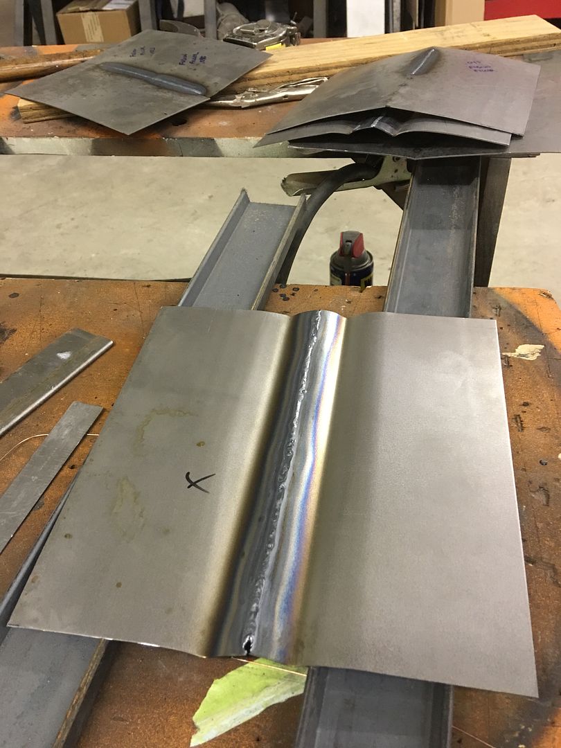
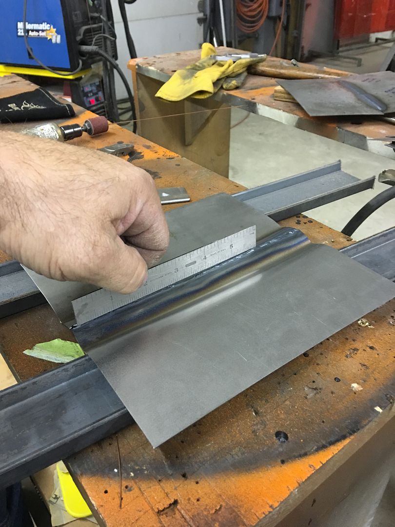
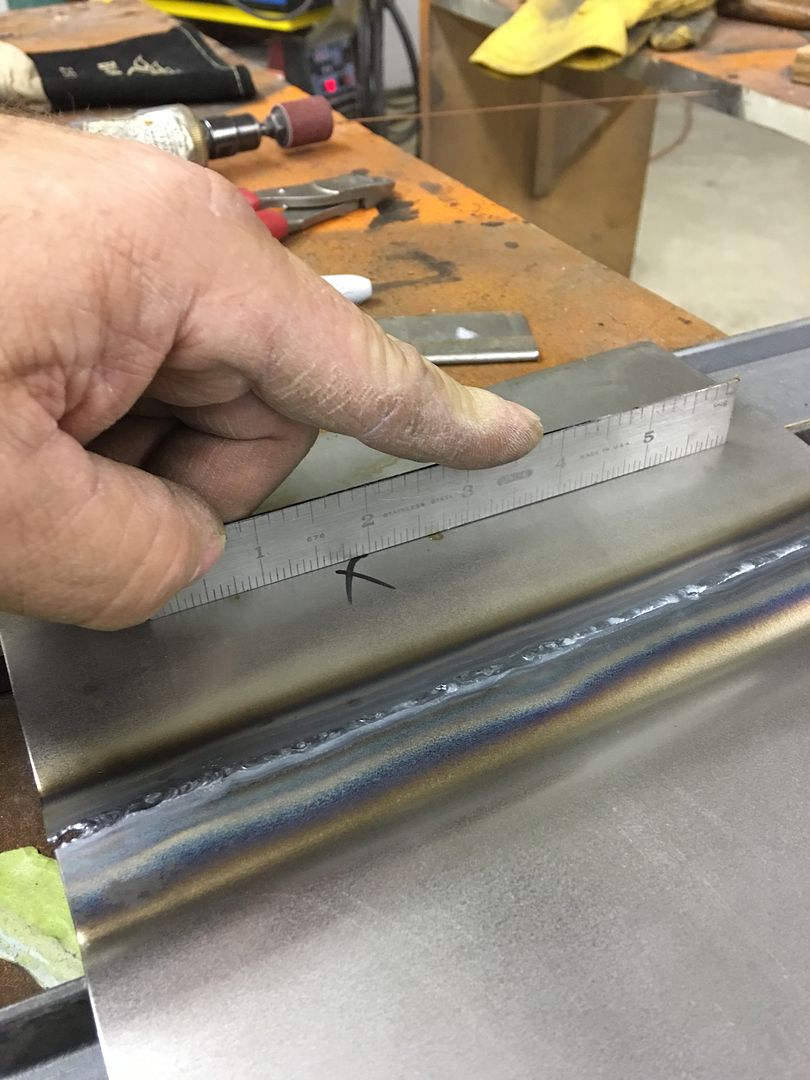
The ghost line shown in the video I linked was fully welded. It’s my understanding that it stems from two thicknesses of metal expanding and contracting slower than the single layer next to it. These differing expansion rates are what eventually causes the ghost line, even through filler. Think of how thick a weld proud can be, sometimes 3 or 4 times the panel thickness, and how the ghost line shown was created by only two panel thicknesses. The other consideration is that planishing helps to normalize the stresses across the weld so it more acts like the single panel that existed prior. Having weld proud left behind can’t help, in any regard.

Good explanation. I completely understand now. I was under the impression Ghosting only occurred on lap joints but, that is not the case. Ghosting can also happen on a butt welded joint if the welds are not ground flush on "both" sides.

This is really a game changer for me on how I approach a panel weld. I had recently read a comment from D.A.T what it takes to do a quality patch repair. The main point I understood from him was it's going to take being able to have access to both side of the panel, which may require removing braces and or, body panels.

My car had many small holes from dent pulling that where filled with filler before I started this project. I had mig filled those holes. I did use a copper backer when mig welding the holes, however........ I did't see a need at that time to make sure the weld on the back side of the hole was perfectly flush with the panel. Even using the copper backer, I would safely assume the weld is at least a couple thousands proud on the backside. Some of those holes would require removing quarter panels to have access to the backside. Now I'm questioning myself thinking filler would have been the better option to avoid Ghosting spot welded holes. Maybe this is the push I needed to replace the quarter panels with aftermarket panels.

So much yet to learn.
 
Last edited:
Good explanation. I completely understand now. I was under the impression Ghosting only occurred on lap joints but, that is not the case. Ghosting can also happen on a butt welded joint if the welds are not ground flush on "both" sides.

This is really a game changer for me on how I approach a panel weld. I had recently read a comment from D.A.T what it takes to do a quality patch repair. The main point I understood from him was it's going to take being able to have access to both side of the panel, which may require removing braces and or, body panels.

My car had many small holes from dent pulling that where filled with filler before I started this project. I had mig filled those holes. I did use a copper backer when mig welding the holes, however........ I did't see a need at that time to make sure the weld on the back side of the hole was perfectly flush with the panel. Even using the copper backer, I would safely assume the weld is at least a couple thousands proud on the backside. Some of those holes would require removing quarter panels to have access to the backside. Now I'm questioning myself thinking filler would have been the better option to avoid Ghosting spot welded holes. Maybe this is the push I needed to replace the quarter panels with aftermarket panels.

So much yet to learn.

I highlighted a part of your post above.. Can happen. Not saying it will, but as with anything bodywork, cheaper to fix before paint goes on. I would just SUGGEST that just the possibility of ghosting should sway someone to change their methods to minimize the possibility.

I don't think you will have any issue with your welded holes. Typically a copper backer is going to get you as flush on the back as you can for working from the outside. A couple of thousandths as compared to panel thickness of roughly .040 is nothing to worry about IMO. And I would also say that welding a hole is a better long term option over just using filler..
 
  • Like
Reactions: MJM
I have welded a a lot of holes shut and if they are ghosting then I’m don’t have a good enough eye to be able to see the ghosting.
 
I have welded a a lot of holes shut and if they are ghosting then I’m don’t have a good enough eye to be able to see the ghosting.

Go back and watch the tailgate video. Watch closely and you can pick up the cleco holes above the ghost line that were welded closed.
 
im not being a smart ass at all, since i have very much enjoyed reading what he could have done different. i am here to learn after all.
however, not much has been suggested to fix the oil can issue. since hes got the patch in, what could he do now?
some body else suggested warming the area and smacking it with a pick hammer. i expect he watched the same video i did on that and it seemed to work.
certainly some one here has way to help ol Lizer? i mean he did say he was looking for a hack..........a trick if you will.
The problem with my oil can is it is there because of shrinkage that has occurred. Further heating it won’t help, only to make it worse. My only repair option is to open it up at this point to relax the metal and do a fix from there.

For using MIG, I set the heat high enough to get full penetration weld with each singular tack, wire feed faster (as needed to prevent blowout), and duration of trigger pull shorter to keep the weld flatter. Practice is suggested to get the welder dialed in prior to working on your good panel.

The weld is going to swell when it heats up and when it cools it will shrink slightly more than it’s original state. For a single tack by itself, it will shrink/ pull inward from all directions (circumferential shrinking). For any attempt to stretch this back out without adding in too much stress, my thoughts are that you will get more stretch out of a larger weld tack than after it has been ground down to panel thickness. Having a weld proud front and back means any planishing attempt should hit the weld dot only (and push the stretch outward circumferentially) for an easier effort in keeping the panel flat. If the weld were ground down, or if there were multiple welds , it’s more possible that the panel could get deflected. And for returning the panel back to its original shape (removing any wave), that is an easier task early in the process when the shrinking effects we are trying to correct are isolated to the one weld tack.

Also, if you were to grind flush first, any planishing effort is going to thin the area thinner than panel thickness.

Before cutting out and rewelding, I would rather see some profile templates at the weld, one inch and two inches away from the weld, and across the weld. If you have done no or minimal planishing, I would expect to see a sinusoidal wave just above and below the weld. Weld shrinkage is pulling things together, and the area just outside this is buckling up and down as the unshrunk metal looks for somewhere to go as it’s being pulled along for the ride. I’d try some planishing first.
I’ve done a lot of planishing at this point but to no avail. There’s definitely a wave through the panel above and below the weld.
 
Oil cans are one of the hardest things to teach IN PERSON, now add in the fact we have inadequate pictures to read a panel. I did suggest this:
Before cutting out and rewelding, I would rather see some profile templates at the weld, one inch and two inches away from the weld, and across the weld. If you have done no or minimal planishing, I would expect to see a sinusoidal wave just above and below the weld. Weld shrinkage is pulling things together, and the area just outside this is buckling up and down as the unshrunk metal looks for somewhere to go as it’s being pulled along for the ride. I’d try some planishing first.

….which should give a better idea of what he has to work with. It’s difficult to give any spot on suggestions without more information. I’ve posted the oil can write up before, and even with that as a guide it is easily misinterpreted. With some pictures using profile templates it would help to better decipher where to attack next.
 
The problem with my oil can is it is there because of shrinkage that has occurred. Further heating it won’t help, only to make it worse. My only repair option is to open it up at this point to relax the metal and do a fix from there.


I’ve done a lot of planishing at this point but to no avail. There’s definitely a wave through the panel above and below the weld.
good luck man, i am not in any way a metal shaper. would love to hear and see how it turns out though.
 
The problem with my oil can is it is there because of shrinkage that has occurred. Further heating it won’t help, only to make it worse. My only repair option is to open it up at this point to relax the metal and do a fix from there.


I’ve done a lot of planishing at this point but to no avail. There’s definitely a wave through the panel above and below the weld.

The weld shrinks. The panel about 4-6” outside the weld wants to stay flat. The area between these differing forces is buckling as one side of it wants to be flat, the other side wants to draw together. So you wind up with a wave in the middle of those two areas. The wave goes away when the weld gets planished adequately to remove the shrink. If you could take some pictures with profile templates to show a better panel read….
 
What is a good way to make a profile template that large ?

Here are some more pics. But it’s very difficult to see the warpage. My hand is laying in a giant low spot. Where the corner is welded is a large high spot there. And all through that wells there is no crown, it’s just very floppy.

Additionally, the contour of the skin patch is flatter than the contour of the rest of the lower door. The body line is crisper on the patch as well, as you suspected. Even if I had no weld problem I’d still be fighting this issue.

So now I’m thinking my best option is to just replace the entire skin.

This all could have been a lot easier if grandpa had just not hit the damn door with the combine.
IMG_3053.jpeg


IMG_3054.jpeg
 
This is a good thread
I'm going to go out on a limb here and say that maybe we are way over thinking to question or topic at hand....how about to cave and pave and move on. There's a hack answer for a question asking for a hack solution =)
 
I don’t really want to do hack repairs. It was just the idea I had seemed very hackish.
 
I highlighted a part of your post above.. Can happen. Not saying it will, but as with anything bodywork, cheaper to fix before paint goes on. I would just SUGGEST that just the possibility of ghosting should sway someone to change their methods to minimize the possibility.

I don't think you will have any issue with your welded holes. Typically a copper backer is going to get you as flush on the back as you can for working from the outside. A couple of thousandths as compared to panel thickness of roughly .040 is nothing to worry about IMO. And I would also say that welding a hole is a better long term option over just using filler..

Thank you for the clarification. I couldn't agree with you more in your first paragraph. As you know, I high respect your thoughts, knowledge and suggestions. This forum has many skillful metal Craftsman suck as Astronaut, Chevyman, D.A.T, Pugsly, and yourself to name a few. The novice metal repair guys on this website are fortunate to have all of you, and you're willingness to help others. It actually pains me when I see a novice brush aside professional advice.
 
Obviously overkill for one panel but I have been following the developer of this planishing hammer for a few years. I’m sure it’s nowhere near as easy as it looks but it’s an intriguing tool. It seems so much easier to use than a hoop style planishing hammer for a repair like this. At least to someone like me who struggles with planishing MIG welds it does.

Mandatory backyard metalshaping hack disclaimer inserted here….

Don
 
What is a good way to make a profile template that large ?

Your local box store should sell some aluminum strips 1/8 x 1". They will make a good straightedge, and if the panel has a slight amount of crown, a shrinker or stretcher set would modify it to match exactly. Absent a shrinker/stretcher set, some strategic hammering on a steel table will provide any stretch needed to add crown to the template.

If the opposite door is still unscathed by farm implements, that would be the ideal place to match the template to. Hindsight and all that, this would have helped tremendously in reading the panel when planishing the individual weld tacks while they are easier to "manipulate".

Here are some more pics. But it’s very difficult to see the warpage. My hand is laying in a giant low spot. Where the corner is welded is a large high spot there. And all through that wells there is no crown, it’s just very floppy.

The damage in the corner is expected, the compounding shrinking effects in the corner make this a guaranteed result. The larger radius in the corner helps to eliminate/minimize this effect. The other option would be a straight weld across the entire door (entire new bottom) to eliminate corners in your patches.
Additionally, the contour of the skin patch is flatter than the contour of the rest of the lower door. The body line is crisper on the patch as well, as you suspected. Even if I had no weld problem I’d still be fighting this issue.

The patch has the benefit of the body crease in the vicinity, so it is less prone to the ugly effects of shrinking. These show a sample done with the weld seam between two creases to show how they control the distortion. Also pay close attention to the sample in the top left of the first picture. The straight, flat panel warps all over with nothing to hold things in check. Same as the middle of a door.


IMG_1997.jpg


IMG_1998.jpg


IMG_1999.jpg


So now I’m thinking my best option is to just replace the entire skin.

Practice is a hell of a tool. Perhaps a new skin is your final option, but you still have planishing that can correct that. What kind of access does the back side have? Were you using flat hammer on outside, dolly on inside? Sometimes the panel doesn't go the way we want it to and it helps to strike it with the hammer from the low side (inward bend of the wave) to better persuade it outward. Since most panels have an outward crown, this means that a hammer used inside the door would need to be crowned as well, to eliminate any coining, and would also need to be short as you can get, for more swing room. Sometimes necessity dictates making your own tools when they don't exist.. This Snap on hammer was modified twice to get it as short as possible, and notice the final version has a slight angle to allow more finger room.

Picture 846.JPG


Picture 849.JPG


IMG_6782.JPG


This hammer has come in handy on many occasions.....


This all could have been a lot easier if grandpa had just not hit the damn door with the combine.View attachment 27182

View attachment 27183
 
Last edited:
MP&C that 3" channel looks more like what im used to. i am getting a lot from these posts, thanks for taking the time to do this.
 
i guess my mind works different. welding between two creases, it moves less because of the structure. same reason that channel is stronger than flat even if it was thicker steel, and box tube even stronger.
it is fair to say all metal moves to an extent? i once built a root rake with 1" flat stock and 1/2" wall 5" tube. 8' wide, it had a very slight warp the entire length. it turned out an advantage since the warp made it slightly concave at the face of the rake, but i didnt mean to make it that way.
 
Indeed, 19 gauge steel or 1” thick plate, it all shrinks. When shaping a panel on a power hammer or English wheel, one of the last things done is to add any creases. This is because the crease acts as a lock to prevent adding any more shape. The same holds true in using body lines next to your welds. The crease side will prevent/severely limit the damage from crossing, if the other side is flat it will experience all the damage. So the IDEAL location is between two creases to keep the damage from pulling at the low crown areas.
 
Obviously overkill for one panel but I have been following the developer of this planishing hammer for a few years. I’m sure it’s nowhere near as easy as it looks but it’s an intriguing tool. It seems so much easier to use than a hoop style planishing hammer for a repair like this. At least to someone like me who struggles with planishing MIG welds it does.

Mandatory backyard metalshaping hack disclaimer inserted here….

Don

Even though I really like tools, and that planishing hammer you have shared is way cool. I bet in the wrong hands would cause tremendous damage if not used properly. It has an extremely large surface area compared to a manual plashing hammer or typical hoop air driven hammers.

I do like how it was used in the video. It looks like a time saver.
 
Back
Top