You are using an out of date browser. It may not display this or other websites correctly.
You should upgrade or use an alternative browser.
You should upgrade or use an alternative browser.
Patch panel advice needed
- Thread starter Chris_Hamilton
- Start date
Chris_Hamilton
Trying to be the best me, I can be
This turned into a good discussion. Thank you Robert for you thoroughness and always excellent pictures.
@anotheridiot
try what MP&C said. Once you switch to solid and use the right technique you'll never go back to using flux core (at least for sheet)
@John Long
Deck lid looks great. I know there was a pile of work in that.
Resigned myself to cutting it out proper and butt welding it. Made a slapper tonight out of a thick leaf spring with enough offset so I can reach it through the tail light hole. And because I can't get enough punishment") I'll probably end up gassing it so fingers crossed.
I'll probably end up gassing it so fingers crossed.
@anotheridiot
try what MP&C said. Once you switch to solid and use the right technique you'll never go back to using flux core (at least for sheet)
@John Long
Deck lid looks great. I know there was a pile of work in that.
Resigned myself to cutting it out proper and butt welding it. Made a slapper tonight out of a thick leaf spring with enough offset so I can reach it through the tail light hole. And because I can't get enough punishment
I'll probably end up gassing it so fingers crossed.MP&C
Member
Not to pick on your method, but this is another good discussion point....
All steel will shrink after the weld cools. From 19 gauge to 1" thick steel plate, IT ALL SHRINKS. The downside to gaps is it allows the panels to pull together, in effect you are losing some of your crown and creating a low. Continually cutting a gap with the .035 wheel shows it continues to pull the panel with each subsequent weld, creating more of a low as you progress, especially if you continue to open up a gap.
The No-gap was intentional, especially with a roof panel, we don't want lows pulled downward that will be visible at eye level. Having the tight joint keeps the crown that you have in the panel, and keeps it consistent. All welds shrink so we should be planishing regardless.. I find it easier to planish the MIG welds while they are all by themselves, then grind to just above flush. This also serves to keep the panel as close to original thickness so your welder setting remains consistent for the same thickness metal. MIG dots left intact with all that extra mass (up to about 5X the panel thickness depending on technique) would be more of a heat sink and cause that cold weld that stands up taller.
More heat, slightly more wire feed to prevent blowout, and much less time on the trigger pull should get you flatter weld dots, for easier planishing and much less grinding. Practice with some scraps the same thickness as the panel you're working on to get the machine dialed into the sweet spot for flatter weld dots with good penetration through.
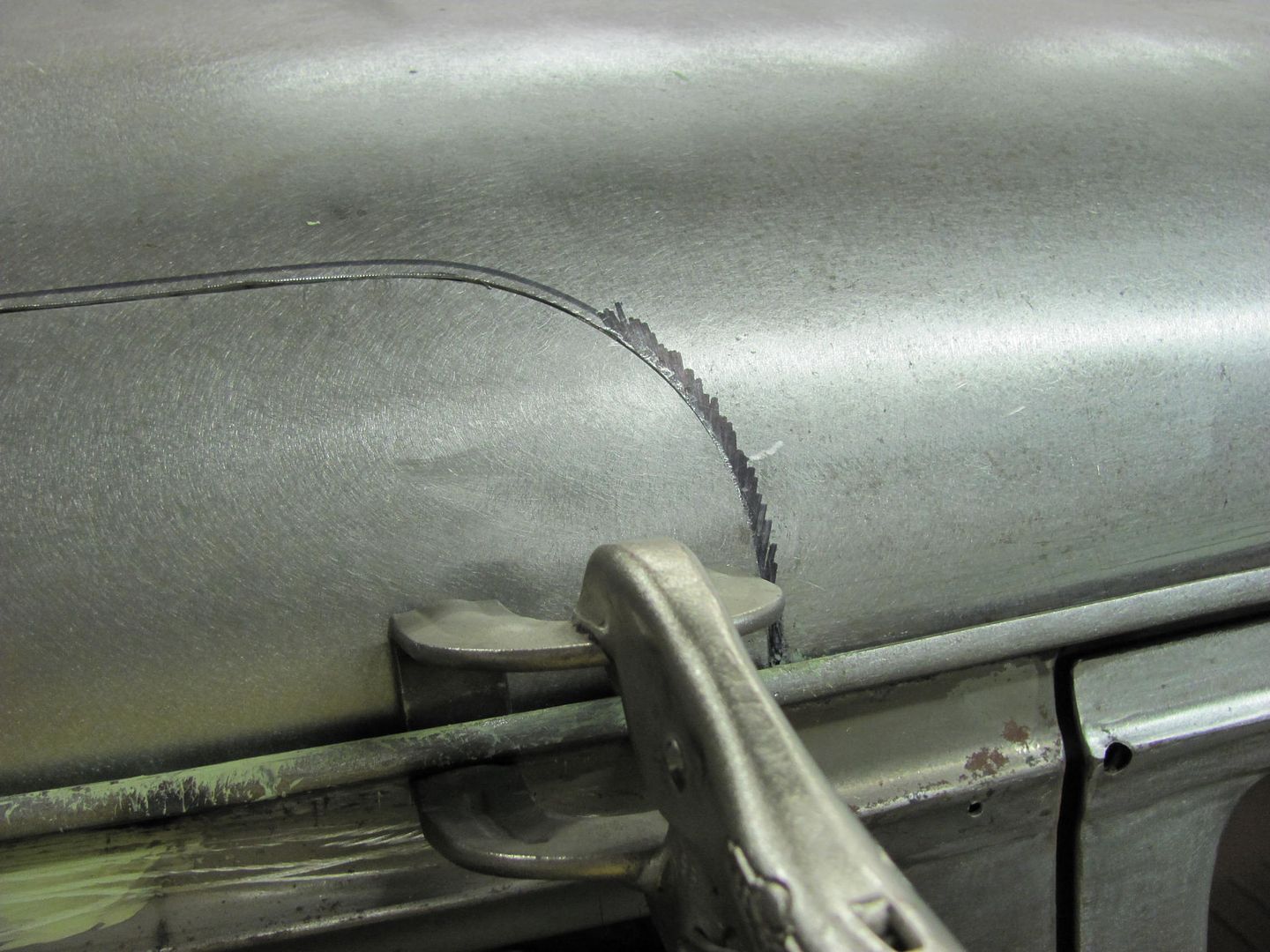
Here's my trimming process for that same weld seam in the roof:
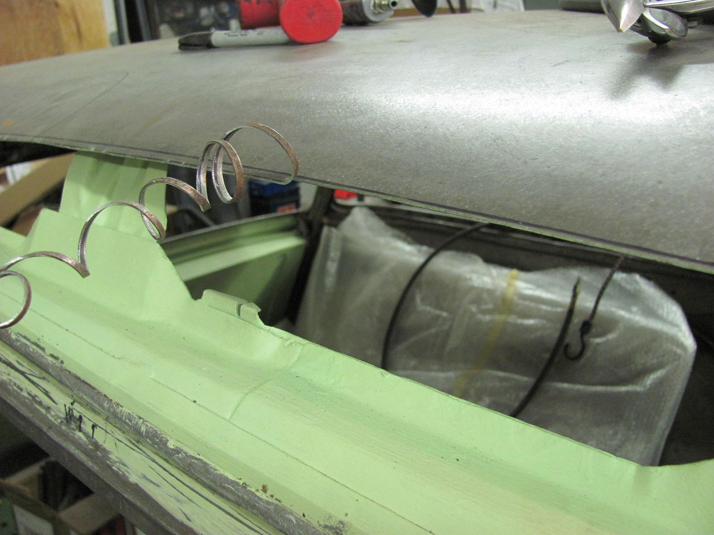
The lower corners of the opening were trimmed to size so that the roof patch could be clamped down into the drip rail. This will help to get more accurate markings on the roof skin for trimming the rest of the opening.
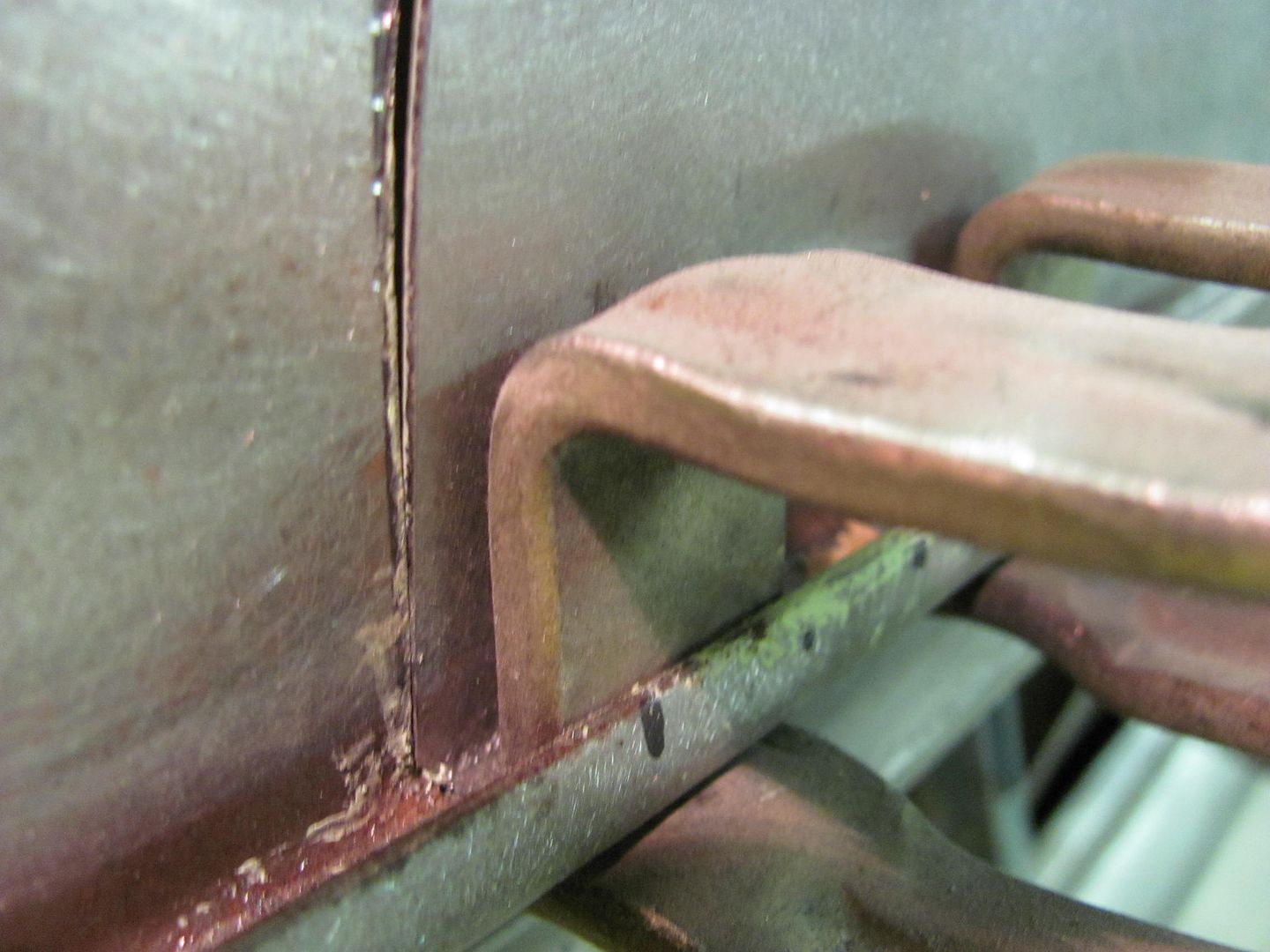
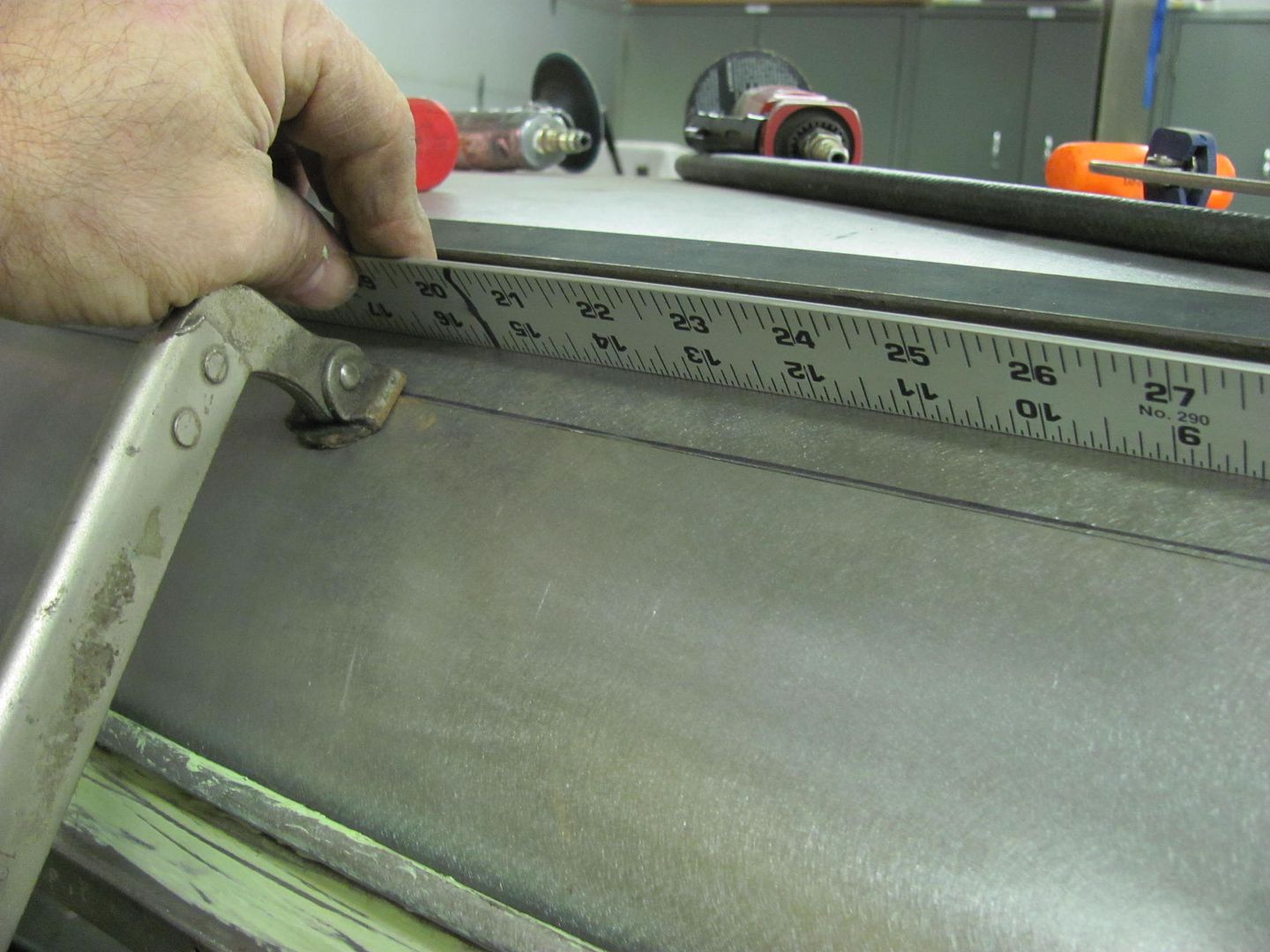
C-Clamp vise grips added to secure the overlapped panels for marking, then a straightedge used to read the crown of the roof to insure there were no dips or puckers along the top of the joint....
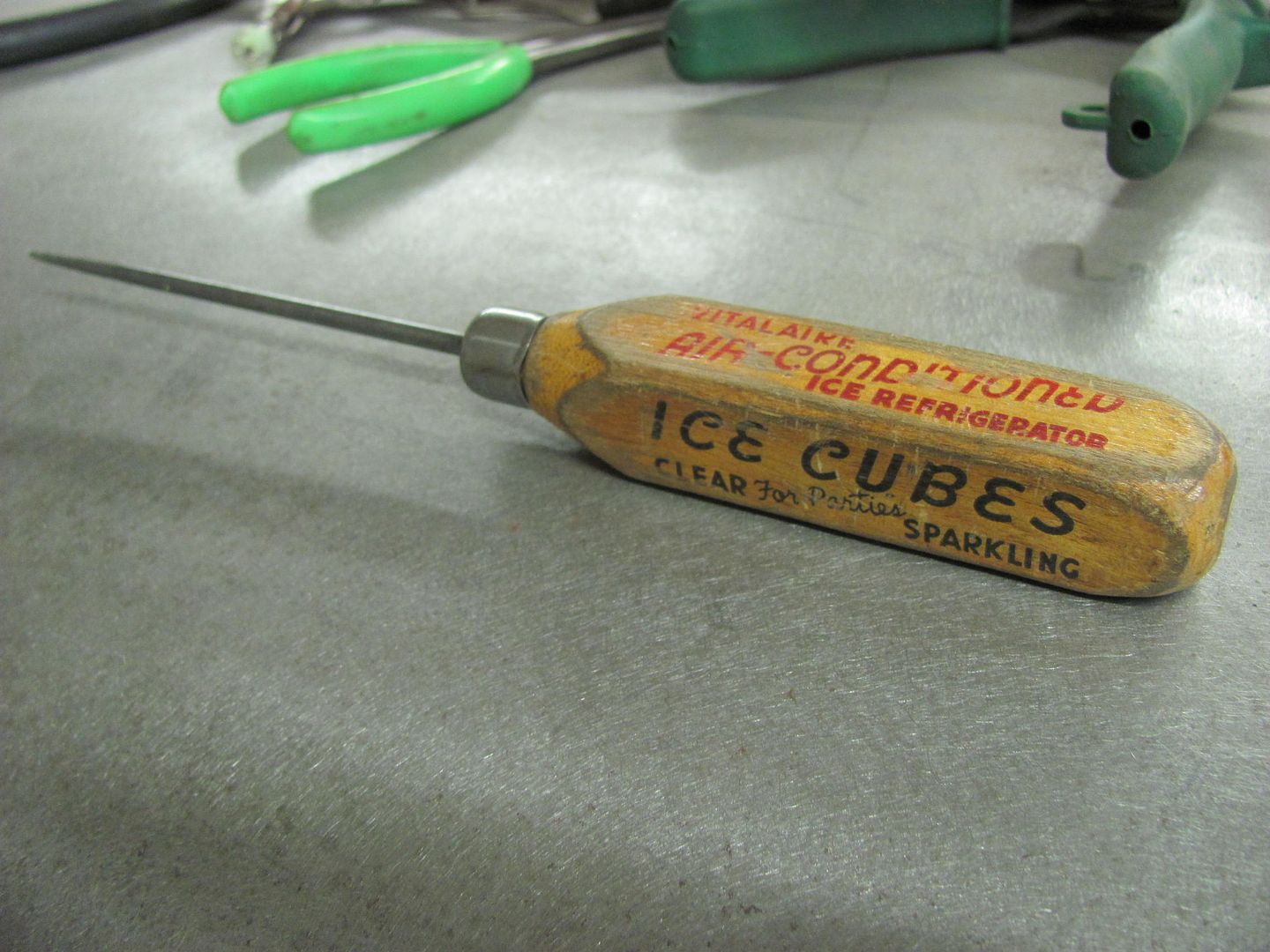
My favorite scribe, a local auction purchase...
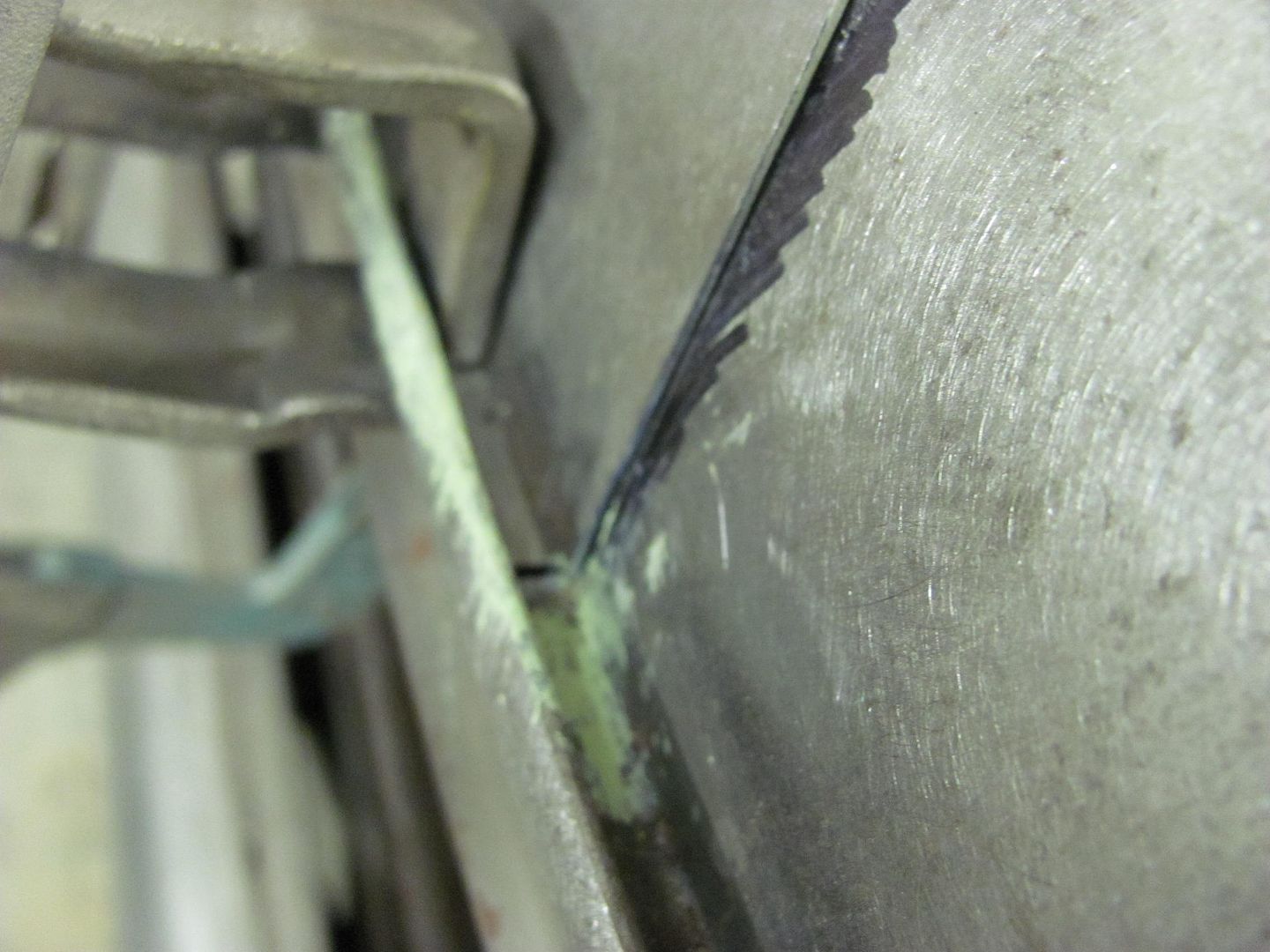
Scribing the roof panel
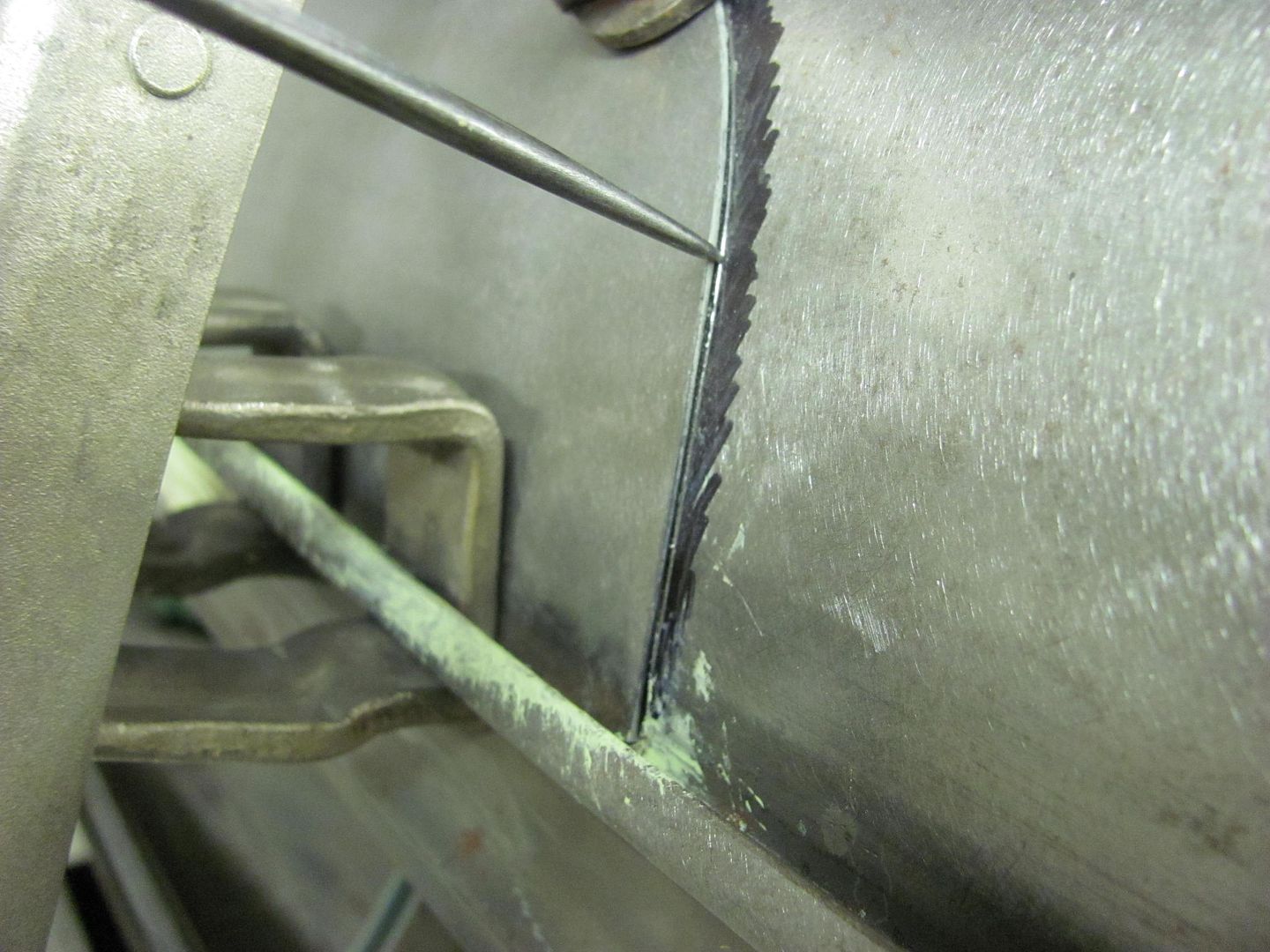
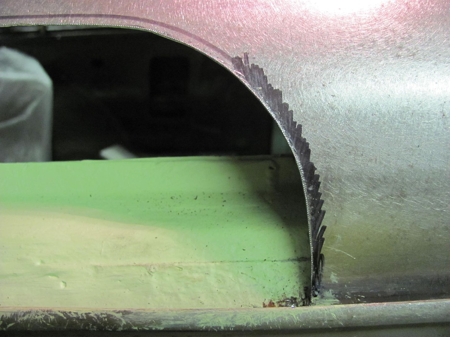
Not much to spare! Trimmed the opening with some offset snips...
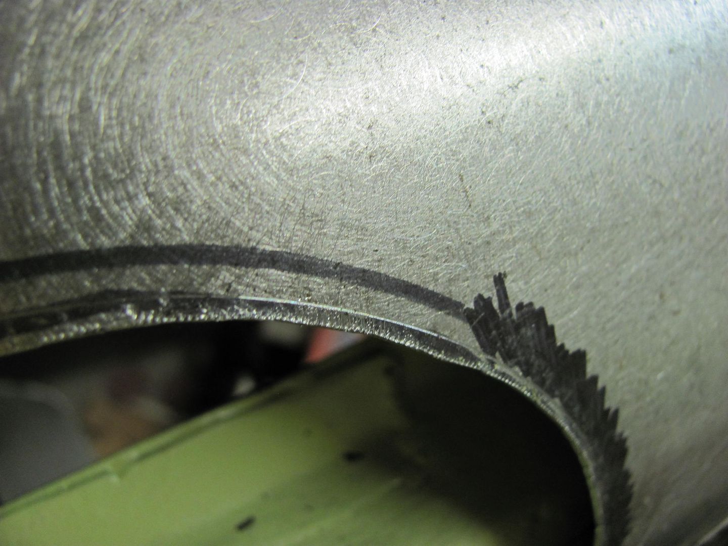
Corners touched up with a 1-1/2" drum sander
Spotting sheet metal closes the gap quite a bit where I need to keep opening up the space with an .035 wheel to keep it from warping.
All steel will shrink after the weld cools. From 19 gauge to 1" thick steel plate, IT ALL SHRINKS. The downside to gaps is it allows the panels to pull together, in effect you are losing some of your crown and creating a low. Continually cutting a gap with the .035 wheel shows it continues to pull the panel with each subsequent weld, creating more of a low as you progress, especially if you continue to open up a gap.
Like on that picture above, you can see the metal already with no gap whatsoever, so when that weld is finished, its probably gonna have to be hammered flat again. To me, thats the bigger deal, once it gets tacked and the two sides meet, continuing to weld is going to start warping a panel..
The No-gap was intentional, especially with a roof panel, we don't want lows pulled downward that will be visible at eye level. Having the tight joint keeps the crown that you have in the panel, and keeps it consistent. All welds shrink so we should be planishing regardless.. I find it easier to planish the MIG welds while they are all by themselves, then grind to just above flush. This also serves to keep the panel as close to original thickness so your welder setting remains consistent for the same thickness metal. MIG dots left intact with all that extra mass (up to about 5X the panel thickness depending on technique) would be more of a heat sink and cause that cold weld that stands up taller.
More heat, slightly more wire feed to prevent blowout, and much less time on the trigger pull should get you flatter weld dots, for easier planishing and much less grinding. Practice with some scraps the same thickness as the panel you're working on to get the machine dialed into the sweet spot for flatter weld dots with good penetration through.
Here's my trimming process for that same weld seam in the roof:
The lower corners of the opening were trimmed to size so that the roof patch could be clamped down into the drip rail. This will help to get more accurate markings on the roof skin for trimming the rest of the opening.
C-Clamp vise grips added to secure the overlapped panels for marking, then a straightedge used to read the crown of the roof to insure there were no dips or puckers along the top of the joint....
My favorite scribe, a local auction purchase...
Scribing the roof panel
Not much to spare! Trimmed the opening with some offset snips...
Corners touched up with a 1-1/2" drum sander
Last edited:
B
bing98
Thank you John and Robert. The two of you have taught me so much on the various threads I follow here and elsewhere. You two inspire me to keep at it vs throwing in the towel each time I nail my mig welds on the test pieces and then butcher it on the car. The little tips you provide as well as the detailed descriptions and pictures are amazingly informative and helpful. I am extremely fussy about getting it right. Even on the stuff you don't see. So, your willingness to share information in such great detail is much appreciated.
The fact that you both are willing to spend as much time as you do taking pictures and sharing your knowledge it greatly appreciated by myself and I'm sure, many others. Many of us don't have the means to have others do this kind of work for us so in a sense you are helping make it possible for us to participate in this hobby on a much deeper level.
mike
anotheridiot
Member
Not to pick on your method, but this is another good discussion point....
All steel will shrink after the weld cools. From 19 gauge to 1" thick steel plate, IT ALL SHRINKS. The downside to gaps is it allows the panels to pull together, in effect you are losing some of your crown and creating a low. Continually cutting a gap with the .035 wheel shows it continues to pull the panel with each subsequent weld, creating more of a low as you progress, especially if you continue to open up a gap.
The No-gap was intentional, especially with a roof panel, we don't want lows pulled downward that will be visible at eye level. Having the tight joint keeps the crown that you have in the panel, and keeps it consistent. All welds shrink so we should be planishing regardless.. I find it easier to planish the MIG welds while they are all by themselves, then grind to just above flush. This also serves to keep the panel as close to original thickness so your welder setting remains consistent for the same thickness metal. MIG dots left intact with all that extra mass (up to about 5X the panel thickness depending on technique) would be more of a heat sink and cause that cold weld that stands up taller.
More heat, slightly more wire feed to prevent blowout, and much less time on the trigger pull should get you flatter weld dots, for easier planishing and much less grinding. Practice with some scraps the same thickness as the panel you're working on to get the machine dialed into the sweet spot for flatter weld dots with good penetration through.
I guess more of my madness is hammering, then grinding, then seeing all the weld has been ground off where you see a crack of separation. Its not apart, but know it wont take long to actually fall apart. The best welds are always at the beginning for me. I guess the problem is too much grinding and not enough hammering.
as far as the solid wire, I have no trouble with long welds, but just trying to spot it just all craters. No faith. Maybe its getting down to an absolute crawl with the wire to the gas has a chance to get thru the 12 foot cable and where it needs to be.
MP&C
Member
Make sure you're getting full penetration through the panel. The proud you see on the back side should be almost same height as that on the front, where both sides need a bit of grinding to bring the panel back to flush. I have never seen a crack in a steel MIG weld (sheet metal) when it had full weld penetration. Cold welds, sure. Lack of penetration welds, sure.
jlcustomz
evil painter
Chris, I have seen a lot of el camino tailgate license plate pockets for example filled in to recess instead of cut & butted. They ALL ghost horribly in temperature changes and even show ghosting with moisture in the early damp mornings on the thicker areas. Some have ghosting that comes in during high temps & goes away again when cooled off.. Glad to hear you're butting.
For an area where you will have a little thickness of filler over a weld, there are fillers with Kevlar strands or carbon fiber, such as USC carbo sill. Idea is they'll bridge the area somewhat that would be prone to ghosting. Have yet to try the USC, But Don Hutton here says he like it. Sounds good in theory, kinda like using veil with fiberglass.
I'm not where I wanna be on steel sheet metal welding either. On 18 gauge, I love a low pressure torch like the henrob. I can do pretty good at 18 gauge , but 20 is a challenge for warping. Pretty damn hard to beat the penetration quality & weld softness though. Much of my stuff like 80's GM sheet metal or locally available metal has some galvanizing, so that kinda ruins a tig being optimum.
On mig welding, definitely lots of people I know agree with smaller gap is better. Also have had a few other professional people say what Robert said about using fatter mig wire in short bursts instead of the small stuff. I think better available wire is part of that.
If Robert says something that contradicts tradition, I'd much rather try it than argue. Speaking of contradicting tradition, I saw on a how it's made show where the Bentley factory had a rear roof to window area full width seam to weld. They had a body shaped metal clamping jig/ heat sink in place & welded non stop from 1 side to the other. Pretty interesting.
I like to do sample work, but with welding size of actual large parts , coupon sized samples don't teach you everything when it comes to effects from heat & heat needed. Haven't seen cracks from good mig welds either. I worry about pinholes, but some people seem to get by just fine initially filling them with SPI epoxy.
Keep in mind this is just my thoughts, but it didn't get mentioned and may help someone else.I did the fenders first. Cut out the depressed area of the marker light hole (where the marker light bolts in. Made my patch and welded them in. The first one I used Oxy/Acetylene and it went pretty crazy (warping) as I welded it. No real problem as I just hammered and dollied it until I got it straight again. (Oxy/Acetylene welds are soft) But that took a long time so on the other fender I figured I'd MIG it in because i didn't want to spend as long on it. Well doing it the standard way I've always done, by tacking it, letting it cool, spotting it jumping around, eventually connecting the spots etc. the fender went crazy warping a lot. Had to stop several times grind, hammer then dolly to keep it relatively flat. Got it done and flat but that took a long time as well. Thoughts?
When welding in a small patch, the area outside of the seam has a lot of metal to dissipate the heat, but not so much on the inside of the seam (the patch itself), so that uneven heat dissipation causes more than normal distortion. Even on a large patch panel there shouldn't be any square corners. There was a picture on here several years ago that showed the HAZ at a square corner, but I couldn't find it. I would use the mig on that small patch, and wait longer between tacks, since skipping around isn't so effective on a small patch.
Chris_Hamilton
Trying to be the best me, I can be
Thanks for all the advice chevman, Robert, and everyone else. Thanks JL for giving me an answer to my question. Felt like they probably would ghost if I did it that way. When I get ready to do the holes I'll post some pics of my steps in this thread. Might be of some interest or help to others. Peter Tomassini told me once that "metal wants to do what metal wants to do." That has been true with this truck. Welded in some small round patches with gas and had very little distortion. Welded in the cab corners with the MIG and had no very little distortion. Welded those 2 patches on those fenders and they went crazy. Going to get a proper no gap fit on the marker light patches and gas them in as even if it distorts more it will be much easier to planish a gas weld as opposed to planishing MIG welds.
Gas is by all means better, if you can get the leverage for the slapper. Just so others know, the dolly pressure has to exceed the force of the hammer.Going to get a proper no gap fit on the marker light patches and gas them in as even if it distorts more it will be much easier to planish a gas weld as opposed to planishing MIG welds.
I would suggest fusion weld without rod, so you will have a smooth seam on the back side, it also allows you to move along faster, just requires a tight fit. It works really well with tig, just turn the power up, the faster you go the less distortion.
Chris_Hamilton
Trying to be the best me, I can be
You could drill out the spot welds and separate the inner and outer bedside to get access to the back. Of course, you must take the be apart, so it's a lot of work.
Not getting paid anywhere near enough to do that.
Already doing way more than I'm getting paid for on this job.
John Long
Member
Chris, On rare occasions, where I can not easily get behind a panel to planish, I have gently pried it up with a piece of flattened copper pipe. That way, when it is tacked, there is some resistance to it shrinking. You might give it a shot if you can get back there at all.
I can not imagine being able to fusion weld a panel I could not get behind and planish. Granted the O/A will be a softer weld but without the ability to planish it you are going to have a real challenge.
I can not imagine being able to fusion weld a panel I could not get behind and planish. Granted the O/A will be a softer weld but without the ability to planish it you are going to have a real challenge.
Chris_Hamilton
Trying to be the best me, I can be
I'll be able to planish it as I made a slapper with enough offset and length that I can fit it through the tail light opening and from underside. It's thick enough that I'll be able to use it as a dolly. I'll be doing it this week sometime, I'll post pics here of the process.
Last edited:
MP&C
Member
Another tidbit I just remembered, can't remember the name of the guy who did this but he would cut both sides (hole and patch) using the aviation shears.... the ones with the slightly serrated jaws. He claimed that using those shears added an ever so slight amount of stretch as you cut, and with his doing tacks and then fusion welds, the "pre-stretch" was just about enough to overcome the weld shrinking that the seam turned out perfectly. IIRC, this was a single horizontal seam, so in the case of something like Chris is doing here with a small rectangular patch, I would tack all sides and then perform ONE weld at a time along it's entire length (if TIG or gas), planish as need be, and make sure panel is cool to touch before starting on the next of three welds.
Here is a thread by Ricard Crees (The Rod Doc) where he shows fusion welding a door skin with almost zero deformity. He may have been the one who mentioned using the aviation snips, but I couldn't find that to be sure..
http://www.allmetalshaping.com/showthread.php?t=1116
As with anything, before jumping in head first practice with some scraps. About once a month or so I cut some 19 ga pieces and gas weld just to keep up on it. If trying a new process (like shown in above link) be sure to read all his posts in that thread first to glean all the helpful hints, and then practice, practice, practice!
jcmeyer5
Having fun learning!
I just did the same thing on my dad's 69 Dart. I did the passenger fender first (off the car). I used MIG and the tack-and-move methodology. Warped to high heaven. Was able to get it straightened out enough to make it work (that fender is already a hot mess from previous collision damage). Did the markers on the quarters the exact same way... no warpage at all. I think the fender warping had to do with a) it was already tweaked from previous damage, and b) the fender was "free" to move as it was sitting on the work bench and not on the car.... probably not as big a factor as the first, but something.
EDIT: didnt have to do the driver fender as it was from a 67 that didnt have markers in it.
EDIT: didnt have to do the driver fender as it was from a 67 that didnt have markers in it.