Paint booth and filtration for air lines, help

612ride

Promoted Users
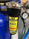
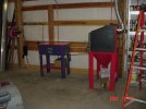
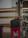
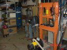
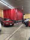
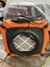
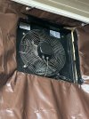
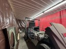
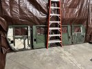
I have never painted a car before. I oil base enameled our entire house about 20 years ago. 17 interior doors, entire kitchen, trim on doors, trim on 19 windows and ton of baseboard. It turned out perfect. A ton of prep work and 2 coats of primer and 2 top coats with sanding in between each coat. I know prep work is a huge part of the finished product. My worries now are that this is a completely different animal. The photos show what I have done so far to get an area to paint in, in my shop. I could use some advice on anything else I should be doing. Specifically, I want to make sure my filtration and dryer from the compressor is good. What do you guys recommend for a set up for making sure I have clean and dry air going to the end of the gun. I set up curtains for the spray area that are all Velcro’d together. I was planning on using the air scrubber, for the supply air in the booth, and the exterior exhaust fan for the shop. Am I an idiot with my plans?
 

Attachments

  • A1F75361-26D1-433C-91D1-A167BC3A645C.jpeg
    A1F75361-26D1-433C-91D1-A167BC3A645C.jpeg
    211.7 KB · Views: 131
  • CFC23C85-A9B0-4FE0-BA55-7E8412F697E5.jpeg
    CFC23C85-A9B0-4FE0-BA55-7E8412F697E5.jpeg
    218.1 KB · Views: 131
  • 80B95993-5760-4119-8081-C0B7B30A082A.jpeg
    80B95993-5760-4119-8081-C0B7B30A082A.jpeg
    179.9 KB · Views: 112
  • 1F690CA7-321B-4E5C-A162-7B403F396FC4.jpeg
    1F690CA7-321B-4E5C-A162-7B403F396FC4.jpeg
    193.3 KB · Views: 123
  • C891D85E-F80D-4068-B02C-2CE46E8D874B.jpeg
    C891D85E-F80D-4068-B02C-2CE46E8D874B.jpeg
    193 KB · Views: 125
  • 3193E0F5-42DD-45E4-8987-4A0C2F17A5FD.jpeg
    3193E0F5-42DD-45E4-8987-4A0C2F17A5FD.jpeg
    241.6 KB · Views: 157
Osha wouldn't approve, but you're way ahead of what most of use had set up on our first paint job. running the exhaust fan as slow as you can get away with will help with having less dirt get into the finish, as most of it comes from the air getting stirred up or off of the painters clothes. Also keep the hose end off of the floor between coats, that also bring dirt up to where it shouldn't be. The other common issue is moisture in the air lines. Having a good moisture trap as far away from the compressor as possible will trap more then one that's in the hotter air close to the compressor.
 
Will this be ok for the water and filter? It’s mounted right next to the compressor, but I have 25’ of hose coming out of the compressor, before it goes into this. Should I have a water separator before this also?
 

Attachments

  • 30F9E732-29B8-4C4C-B1C5-781F3D784600.jpeg
    30F9E732-29B8-4C4C-B1C5-781F3D784600.jpeg
    166.1 KB · Views: 188
Those are very good. The actual location doesn't matter as much as the amount of cooling allowed by the type or length of air line going to the drier. Copper or aluminum will give you the most cooling before getting to the drier, but I don't see any problem with your set-up now. In the heat and humidity of the summer it will be more important to have the air as cool as possible as it gets to the drier. It will do a better job that way. Also drain your traps often.
 
Will this be ok for the water and filter? It’s mounted right next to the compressor, but I have 25’ of hose coming out of the compressor, before it goes into this. Should I have a water separator before this also?
Won't do much good as the air has to cool and condensate to be filtered out. Those filters don't catch vapor. The hose doesn't allow it to cool as much as copper or iron pipe would. You need 50 feet of 3/4" (minimum) copper or steel pipe ideally between the compressor and the first filter. And you need water traps to allow some of the water that condensates in the line to escape by other means than the filter. You can get 50' by running the pipe up and down the wall if you are lacking space. While it may seem like a pain, it needs to be done or else you will have endless water issues when trying to paint. Cold or hot outside it won't matter.

Do a search here as there is a lot of good info on air piping.

Here is a good basic pipe layout.
pipe-layout-1.gif
Thank you! Can I use 1” galvanized pipe for the system?
 
Won't do much good as the air has to cool and condensate to be filtered out. Those filters don't catch vapor. The hose doesn't allow it to cool as much as copper or iron pipe would. You need 50 feet of 3/4" (minimum) copper or steel pipe ideally between the compressor and the first filter. And you need water traps to allow some of the water that condensates in the line to escape by other means than the filter. You can get 50' by running the pipe up and down the wall if you are lacking space. While it may seem like a pain, it needs to be done or else you will have endless water issues when trying to paint. Cold or hot outside it won't matter.

Do a search here as there is a lot of good info on air piping.

Here is a good basic pipe layout.
pipe-layout-1.gif
I’m a little confused on the filter layout. If I’m only running one line to the paint area, how should the filter setup be? In other words, would I just use a setup like the far right of the photo?
 
I’m a little confused on the filter layout. If I’m only running one line to the paint area, how should the filter setup be? In other words, would I just use a setup like the far right of the photo?
Yes, just ignore the extra driers in the illustration, there just to show how to set up multiple outlets.
 
Thank you! Can I use 1” galvanized pipe for the system?
1" would work well. When I had my first Shop in my late 20's, I used 1 1/4" pipe. Got a bunch of it secondhand cheap. Darn near killed me though trying to hand thread it.
 
Mine when I first ran it. Strapped to the back wall.
50' 3/4' copper in elongated loops with swept turns,no 90's,pitched with drip legs and cocks from the Compressor which has a simple separator at the tank outlet for oil mist mainly and a drain to an A/C unit accumulator tank which has a 'J' pipe inlet and top of tank outlet for water collection and drainage then to other stations thru out the Shop with whatever appropriate connection depending on use. All copper.
As said,Main thing is some Length in order for the Air to Cool off from the compression cycle. If your not running the comp much,this generally happens in the Tank,but when your really humping it,it has to have Time or "something" to remove the excess heat. Your piping will have an impact on this aspect.Black or Galv pipe is fine but you have the pipe Thickness to consider as the thicker the tube,the less heat transference/stratification It has.
Thinner IS Better.
Answer this, Steel/Iron + Moisture + Air =
An Old shop I worked for was previously a small Manufacturing plant and had a Gigantic Westinghouse 80gal 3 phase Air compressor with Black pipe air lines ran everywhere.
I hated even airing up my truck tires.
 

Attachments

  • s'blast cab..JPG
    s'blast cab..JPG
    150.8 KB · Views: 136
  • Sblaster.JPG
    Sblaster.JPG
    212.5 KB · Views: 114
  • shop 1.JPG
    shop 1.JPG
    148.3 KB · Views: 111
Well..............thin-wall schedule 40 steel pipe or thin wall copper tubing may or may not be better than thicker wall schedule 80 steel pipe or the next wall thickness up in copper tube for 3/4" or 1" size. Either way, you're apt to lose 20-30% of your "at the gun cfm flow" if you are not high enough pressure coming out of the tank with all the piping restrictions. The problem there is if you are at say 145-165 psi coming out of the tank--than you even have less time to dissipate heat into the pipe/tube for the air flow since the velocity is higher. It depends exclusively on how you expect to use your compressor. Such set-ups using pipe or tube to dissipate heat out of the moving air stream is by conduction only. Some of the better Ingersoll Rand and Quincy's, Saylor Bealls, etc. have a convection tube cooler with welded or brazed fins on them on the back side of the compressor before it goes into the tank. The curves in the spokes of the pump pulley either push or pull air flow through the cooler. Most are copper tube/aluminum fin and I only got 11 years out of mine before it cracked from fatigue.

The fallacy is that most "box store compressors" run higher RPM motors and pumps with smaller displacement bores. Many of these have a 60% duty cycle or less motor at a 5 HP rating. Check your motor plate. They are smaller motors in physical size and weight with way less copper windings and cannot make 5HP for 10 minutes out of 10 minutes running without overheating and tripping the breaker. You run faster smaller pump pistons to a higher compression ratio to make up for this to get a certain cfm output. The higher the compression ratio the greater the heat. At the end of the day---they are huge hot air and condensed water-pumps if you plan on using them on a continuous daily basis. I've seen some posters on this forum pulling their air out from a thread-o-let or coupler in the shell toward the bottom of the receiver tank. Try to use a tap at the top to avoid moisture condensing and running down the inside of the tank near the bottom.

Thinner tube is the answer when you are going to intermittently use your air source since it reaches equilibrium temperature sooner..............but you want a nice heavy heat sink with thick wall material for continuous operation. You want the tube to keep absorbing heat for longer when you want to use your air source for extended periods of time. When I design and manufacture air receiver tanks for specialized users---I make 80 gallon tanks out of 3/8" or 5/8" thick steel plate for better heat conduction for continuous operation users. Most commodity air receiver tanks are 3/16" for a 80 gallon vertical and 175 psi rating.
 
Will an aftercooler and filter between the pump and tank work as well as 50' of copper after the tank or would a copper loop still be needed after the Tank? I am currently running an aftercooler for intermittent use and get minimal water in the tank and none that i can tell at the tools (no paint yet). I will start painting later this year so I'm collecting tips on how to set up the air lines.

PS. I have asked this before but never got definitive answer.

Cheers,
Emil
 
Well..............thin-wall schedule 40 steel pipe or thin wall copper tubing may or may not be better than thicker wall schedule 80 steel pipe or the next wall thickness up in copper tube for 3/4" or 1" size. Either way, you're apt to lose 20-30% of your "at the gun cfm flow" if you are not high enough pressure coming out of the tank with all the piping restrictions. The problem there is if you are at say 145-165 psi coming out of the tank--than you even have less time to dissipate heat into the pipe/tube for the air flow since the velocity is higher. It depends exclusively on how you expect to use your compressor. Such set-ups using pipe or tube to dissipate heat out of the moving air stream is by conduction only. Some of the better Ingersoll Rand and Quincy's, Saylor Bealls, etc. have a convection tube cooler with welded or brazed fins on them on the back side of the compressor before it goes into the tank. The curves in the spokes of the pump pulley either push or pull air flow through the cooler. Most are copper tube/aluminum fin and I only got 11 years out of mine before it cracked from fatigue.

The fallacy is that most "box store compressors" run higher RPM motors and pumps with smaller displacement bores. Many of these have a 60% duty cycle or less motor at a 5 HP rating. Check your motor plate. They are smaller motors in physical size and weight with way less copper windings and cannot make 5HP for 10 minutes out of 10 minutes running without overheating and tripping the breaker. You run faster smaller pump pistons to a higher compression ratio to make up for this to get a certain cfm output. The higher the compression ratio the greater the heat. At the end of the day---they are huge hot air and condensed water-pumps if you plan on using them on a continuous daily basis. I've seen some posters on this forum pulling their air out from a thread-o-let or coupler in the shell toward the bottom of the receiver tank. Try to use a tap at the top to avoid moisture condensing and running down the inside of the tank near the bottom.

Thinner tube is the answer when you are going to intermittently use your air source since it reaches equilibrium temperature sooner..............but you want a nice heavy heat sink with thick wall material for continuous operation. You want the tube to keep absorbing heat for longer when you want to use your air source for extended periods of time. When I design and manufacture air receiver tanks for specialized users---I make 80 gallon tanks out of 3/8" or 5/8" thick steel plate for better heat conduction for continuous operation users. Most commodity air receiver tanks are 3/16" for a 80 gallon vertical and 175 psi rating.
I have a Quincy QT-54, which is a 2 stage 15 CFM 175 PSI, compressor. I am going to put in 50’ of 1” galvanized to the paint area. Comprised of 8’ vertical, out of the compressor, with a drain at the bottom of that vertical line. 30’ along the ceiling, over to the paint area, and 8’ down to the filter, with the pipe extending lower than that, with a drain. I am extending the horizontal line at the ceiling, a couple of feet past the line going to the filter, and then that will drop down 8’ to a drain.
I've seen some posters on this forum pulling their air out from a thread-o-let or coupler in the shell toward the bottom of the receiver tank. Try to use a tap at the top to avoid moisture condensing and running down the inside of the tank near the bottom.I've seen some posters on this forum pulling their air out from a thread-o-let or coupler in the shell toward the bottom of the receiver tank. Try to use a tap at the top to avoid moisture condensing and running down the inside of the tank near the bottom.
I’m confused by the thread-o-let, in the shell, part of your response.
 
I think a much easier solution is to just install an aftercooler on it for about $130 that will completely cool the air (to room temp) and remove about 90% of the water before it ever makes it to the tank.

After my compressor is another 25’ of 1/2” coiled copper line (an artifact from before the aftercooler), and then it runs through another oil/water separator, then a Motorgard M60 submicron filter, then a desiccant filter to remove any remaining vapor. My desiccant lasts a very long time now since installing my aftercooler.

 
Will an aftercooler and filter between the pump and tank work as well as 50' of copper after the tank or would a copper loop still be needed after the Tank? I am currently running an aftercooler for intermittent use and get minimal water in the tank and none that i can tell at the tools (no paint yet). I will start painting later this year so I'm collecting tips on how to set up the air lines.

PS. I have asked this before but never got definitive answer.

Cheers,
Emil
The aftercooler will work much better than coiled copper. The aftercooler allows the air to cool and remove a lot of water before it even hits the tank. Since the air is already at room temp as it comes out of the tank you could send it straight through to your booth filtration.
 
I think a much easier solution is to just install an aftercooler on it for about $130 that will completely cool the air (to room temp) and remove about 90% of the water before it ever makes it to the tank.

After my compressor is another 25’ of 1/2” coiled copper line (an artifact from before the aftercooler), and then it runs through another oil/water separator, then a Motorgard M60 submicron filter, then a desiccant filter to remove any remaining vapor. My desiccant lasts a very long time now since installing my aftercooler.

Any specific type/brand of water separator and desiccant filter?
 
I have a Quincy QT-54, which is a 2 stage 15 CFM 175 PSI, compressor. I am going to put in 50’ of 1” galvanized to the paint area. Comprised of 8’ vertical, out of the compressor, with a drain at the bottom of that vertical line. 30’ along the ceiling, over to the paint area, and 8’ down to the filter, with the pipe extending lower than that, with a drain. I am extending the horizontal line at the ceiling, a couple of feet past the line going to the filter, and then that will drop down 8’ to a drain.
I've seen some posters on this forum pulling their air out from a thread-o-let or coupler in the shell toward the bottom of the receiver tank. Try to use a tap at the top to avoid moisture condensing and running down the inside of the tank near the bottom.I've seen some posters on this forum pulling their air out from a thread-o-let or coupler in the shell toward the bottom of the receiver tank. Try to use a tap at the top to avoid moisture condensing and running down the inside of the tank near the bottom.
I’m confused by the thread-o-let, in the shell, part of your response.
Thread-o-lets are heavy duty specialized forgings used to reinforce openings on pressure vessels. They set on the outside and over the hole opening. Welding is done through the wall of the fitting to the shell exterior. The better-quality pressure vessels use these rather than threaded couplers welded inside and outside the tank with fillet welds for sizes up to 2 NPS. It creates a gradual transition on the shell of the tank for stress in tension with lots of material reinforcement in the area where burning the hole weakened the shell of the tank. Way better if you ever have to clean-up the threads with a tap.
 

Attachments

  • DSCN3958.JPG
    DSCN3958.JPG
    122.4 KB · Views: 85
  • DSCN3959.JPG
    DSCN3959.JPG
    201.9 KB · Views: 87
Any specific type/brand of water separator and desiccant filter?
Honestly the ones I use were a cheap set I bought at Harbor Freight. But I’ve been using them since 2013 and they keep the air dry.

For my front yard hack use they work fine.
 
Back
Top