mitch_04;35987 said:
I go back and forth, one day my sheet metal repairs go nice and smooth, the next day they sink at the weld and I feel like throwing things, heavy things. My process is this...
1. Lay new metal over old metal, clamp or screw in place.
2. Cut through both layers of metal to ensure cuts match
3. Remove old metal, clamp new metal with vice grips, panel clamps, whatever fits
4. Tack a couple tacks just to hold it in place
5. Go through and bump metal until it lines up, then tack.
6. Put a tack every 2 or 3 inches using above step.
7. Put tacks in between previous tacks, repeat until I have 1/4" lengths to finish weld.
8. Finish weld 1/4" lengths.
9. Smooth large pieces of weld with edge of cut-off wheel.
10. Finish smooth with 36 grit roloc disc.
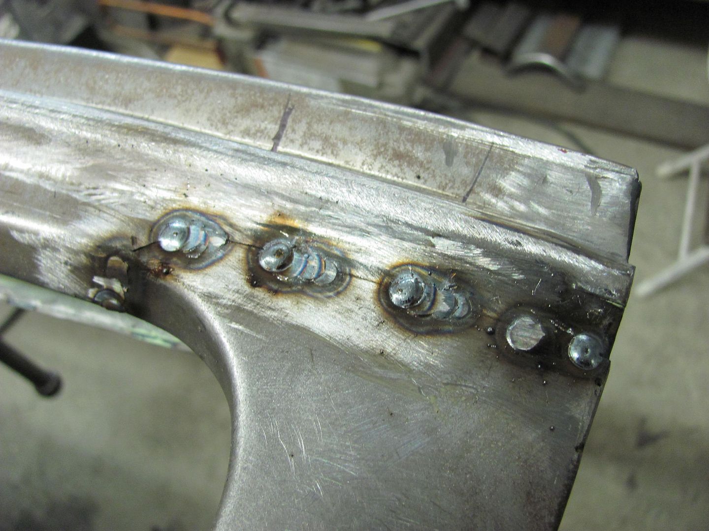
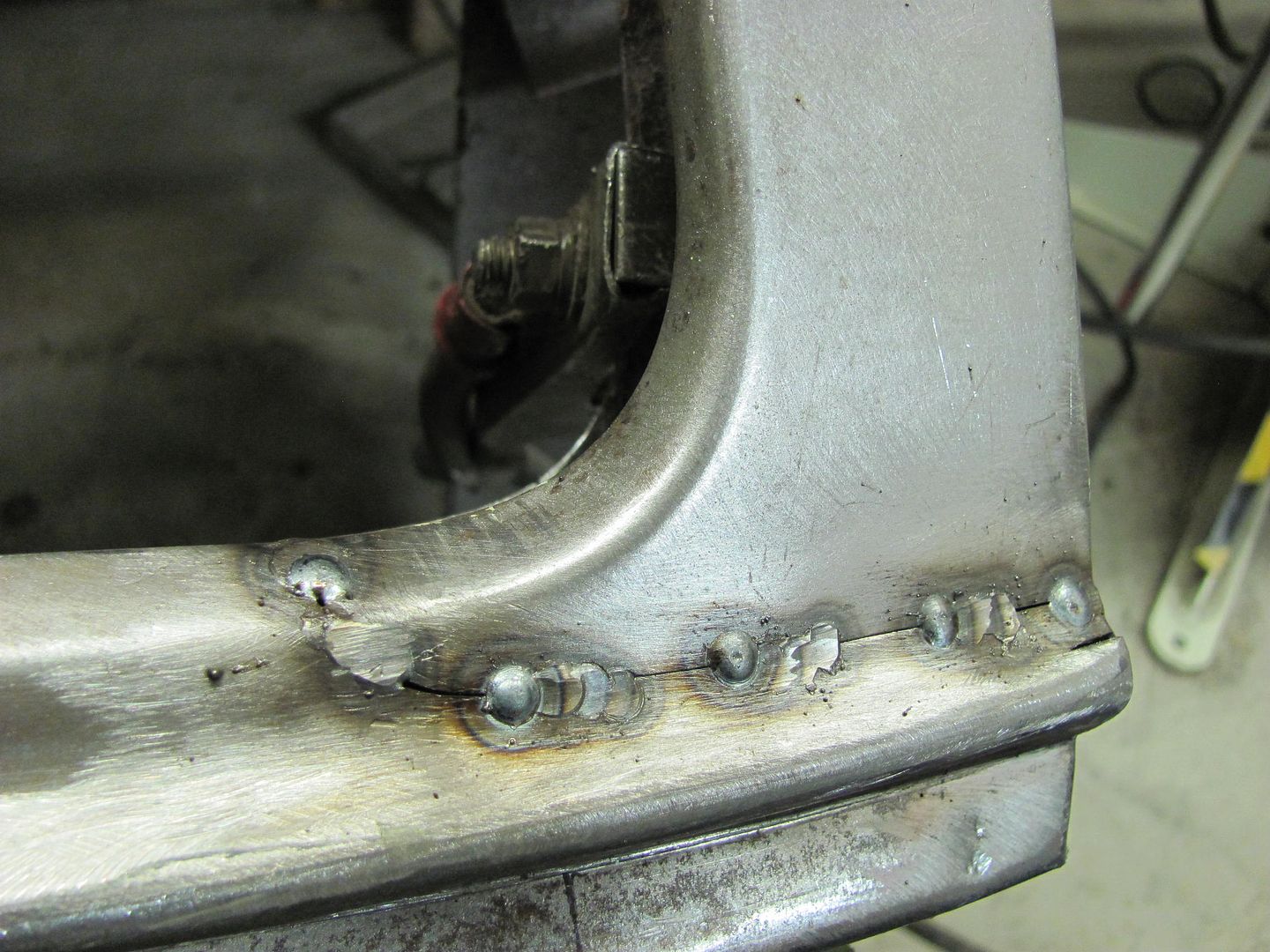
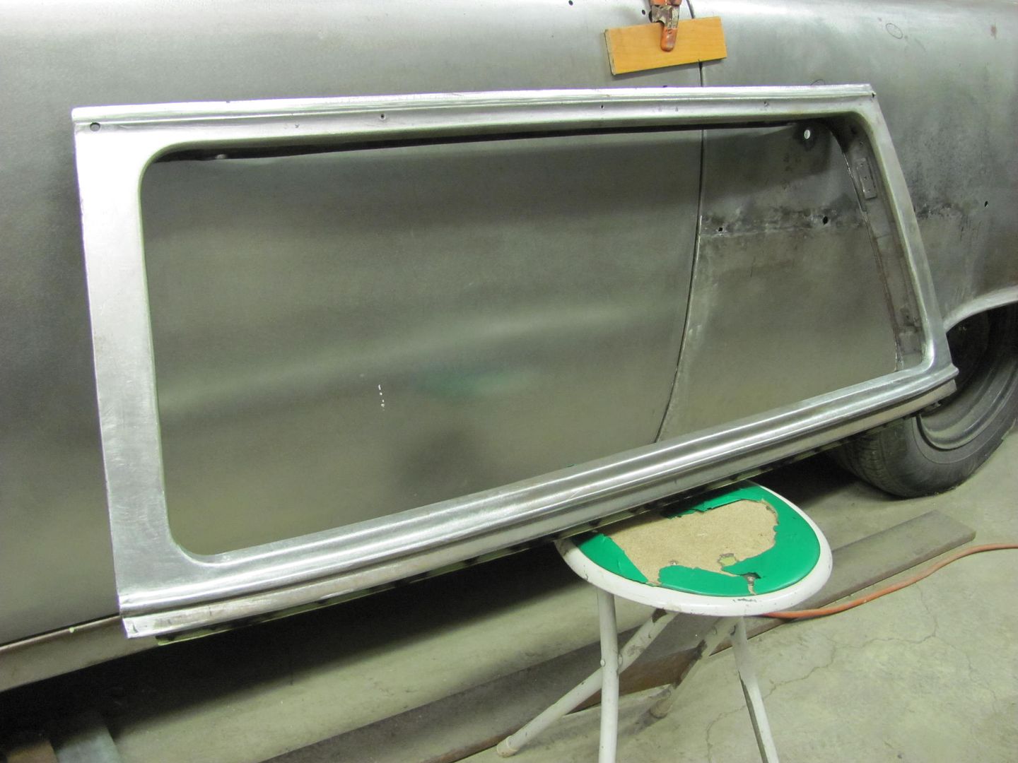
The welds sink in, in some spots, up to 1/8". I try to bump them out as much as possible, but welds don't seem to like to move. I tried to get a good pic, after bumping, but it doesn't really show it well.
Any helpful ideas?
It's hard to see some of what's going on there without the HAZ still visible, but looking at this car (Volvo?) it shows what should be a somewhat flat crown in both the horizontal and vertical directions. Regardless of appearance, all body panels will have crown in at least one direction to help hold the shape of that panel. A flat sheet of metal has no support and will flap in the breeze, so ALL panels will have crown somewhere. If we were to look at the seam along the weld in a cross-section view (top-down) you would see that despite appearing flat, that panel actually has crown from front to back. It looks like a slight arc. Now, anytime you apply the heat from welding, you are going to get a shrink as that weld cools. When we weld one dot at a time, each and every dot is going to pull at the metal around it, from all directions, causing a shrink. Once you've added all those shrinks from all those weld dots together, along the entire weld seam, it adds up to a substantial amount of shrink such that what used to look like an arc is now more closely resembling a straight line. This is why the panel is pulling inward, the crown is shrinking. If this seam were in the middle of the panel, it would appear as a more pronounced valley, but as it is close to the joggle where the panels meet, this helped to hold
some of the shape, or at least to help spread it out a bit more. This is why there is more of a radius in the bottom of your valley.
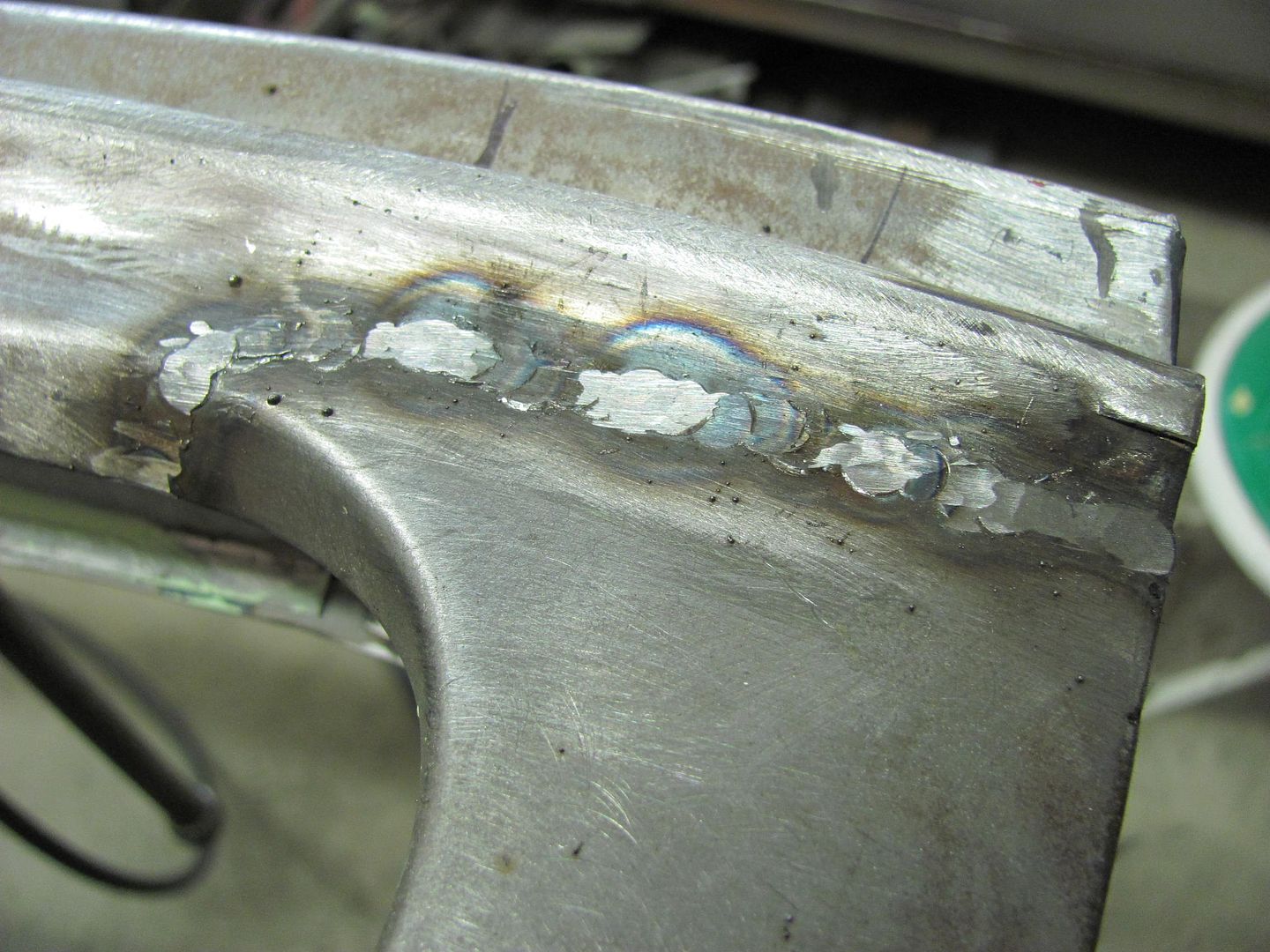
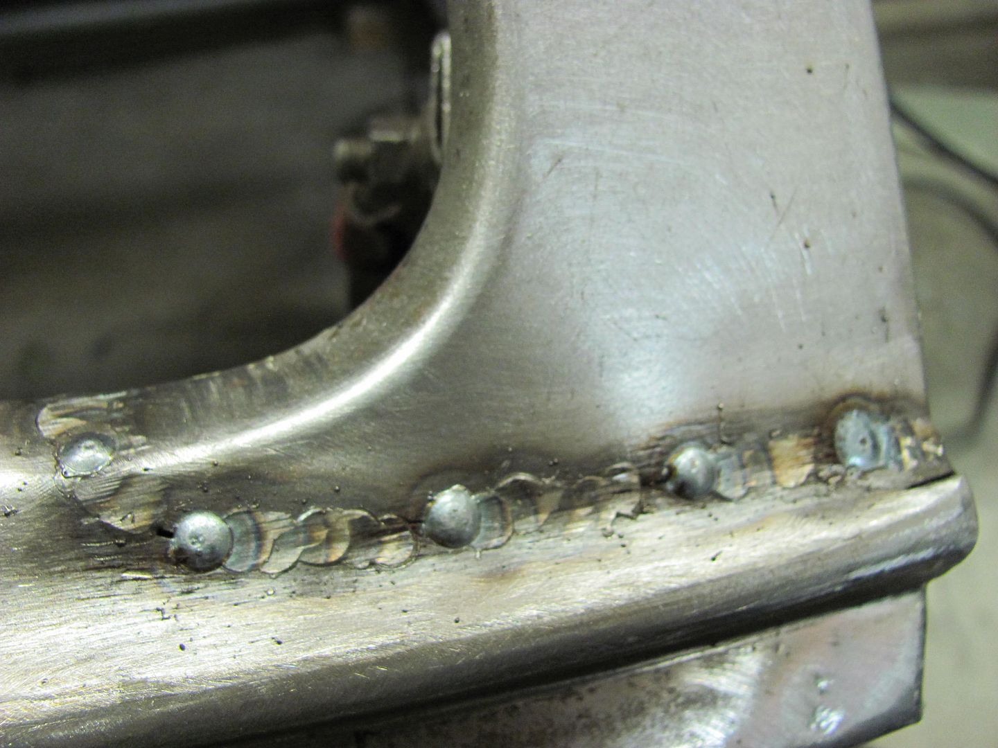
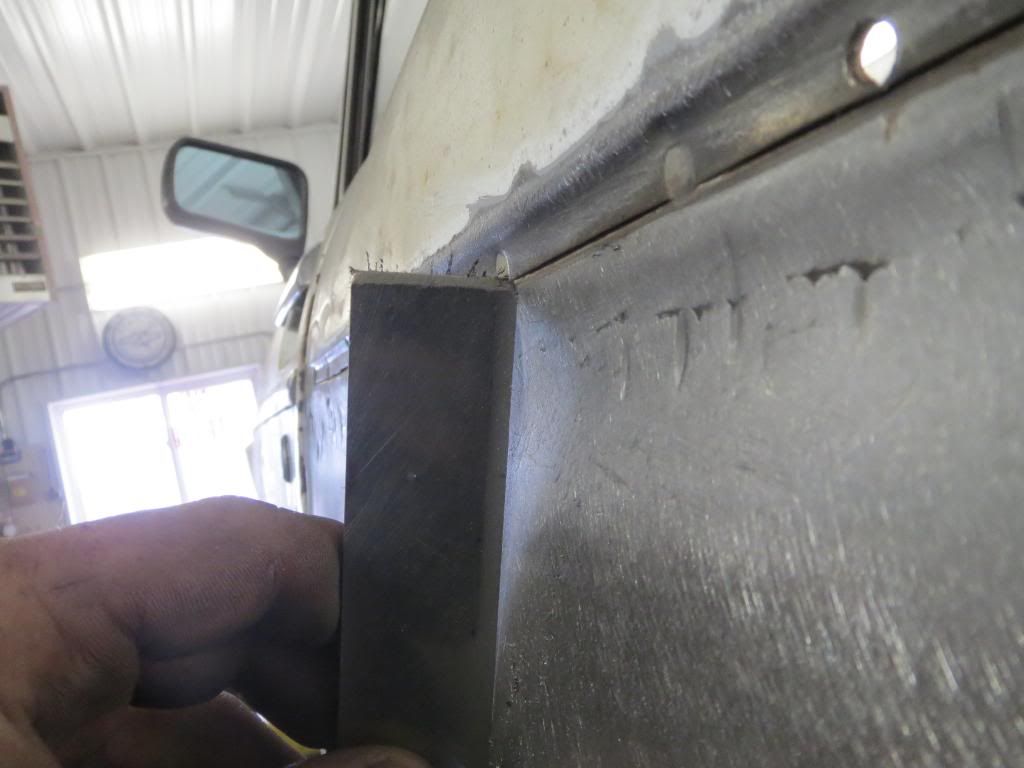
As to how I address these, lets look at this again:
When we weld one dot at a time, each and every dot is going to pull at the metal around it, from all directions, causing a shrink.
I have found that due to the manner in which each weld dot shrink pulls from ALL directions, you will have better luck in planishing to remove said shrinking effects if you can planish the weld dots while they are singular, sitting all by their lonesome. This will more effectively STRETCH that weld dot back out in all directions. And by stretching as you go, you eliminate the panel being pulled into a valley as your picture shows. As far as tacking the panel, you didn't specify this, but you would want to start your tacks at one end and work toward the other. I know many people will tell you to skip around to minimize heat buildup, and I have been one of those. But if you tack one end and then move to the opposite end, you run a greater risk that one panel may have more material than the other. Once things get all tacked up, this results in a panel bulge on one side of the weld. So tacking from one end and working progressively to the other will help to eliminate this by being able to align the panels together as you go. Now that the panel is tacked and weld dots are spaced about (2 or 3"), go back and planish each weld dot individually, to add a bit of stretch. At this point, I use a 3" cutoff wheel to grind down the dots to just above flush. This gets them out of the way for planishing the next sets of dots, and by leaving them just above flush, you can do the final cleanup with a roloc sander all at once. by trying to grind things down to perfectly smooth after each, you run a greater risk of inadvertent sanding of the metal to the sides of the welds, which may thin and weaken the panel. So I hold off on this until the end. For your grinding disc, I prefer to use cutoff wheels about 1/16 thick. This gives a much smaller contact area than most any other method, so you will have less heat buildup from the grinding process. Here is a link showing the grinding method on a plug weld, again, sanding on a weld seam I would wait until the end.
[video=youtube;V2WHT_zMOE8]https://www.youtube.com/watch?v=V2WHT_zMOE8[/video]
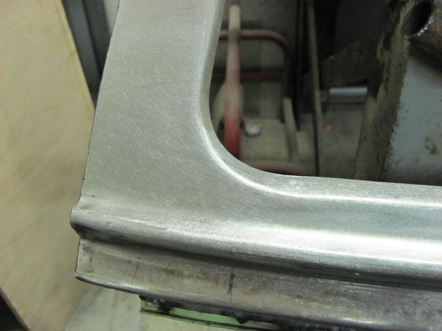
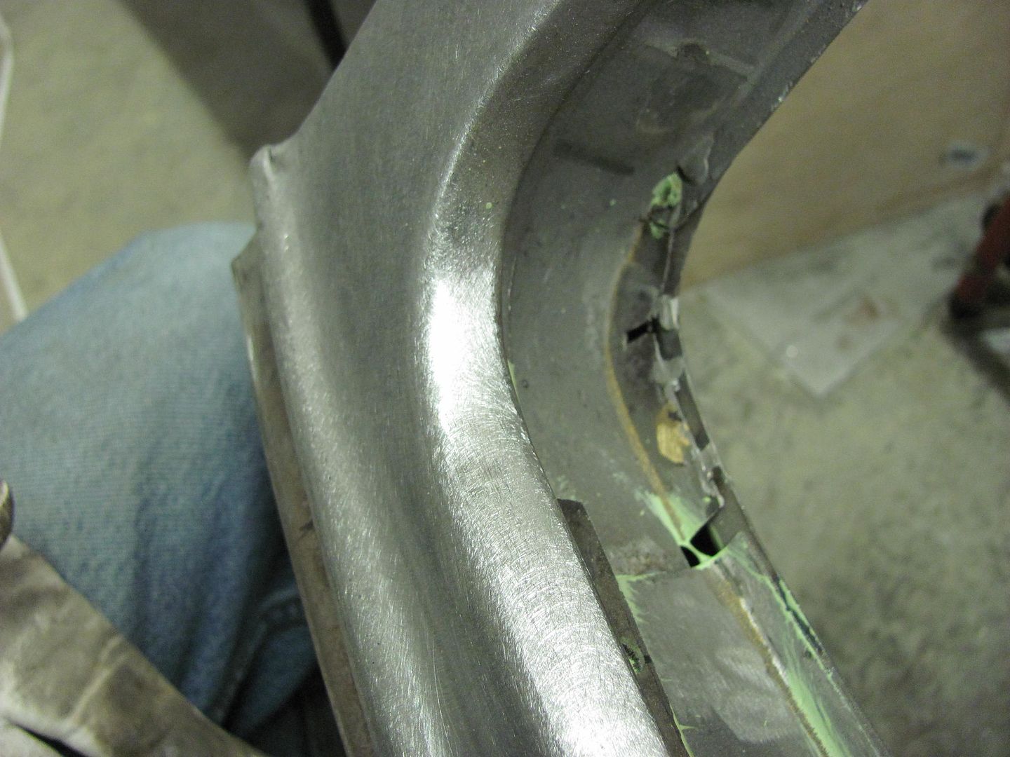
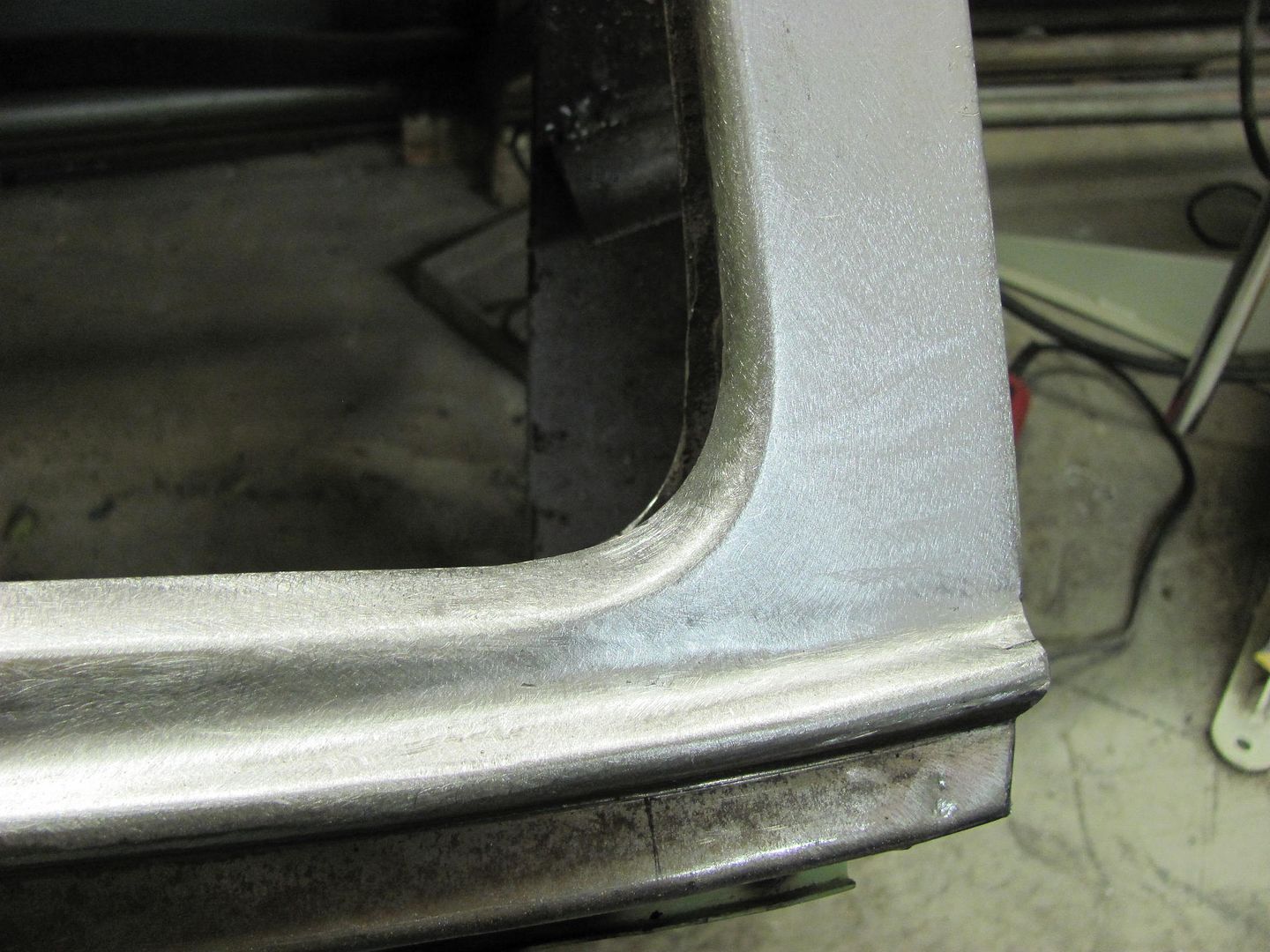
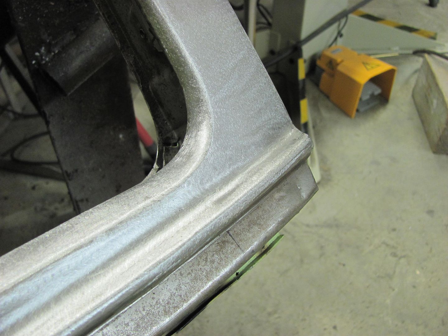
Once these initial welds are planished and ground down just above surface, then continue, adding a weld between each one until your welds are spaced about 1" apart. At this point (still planishing and grinding after each time) instead of hitting the center between for weld location, start overlapping by about 1/3 of the last welds. By overlapping, you will have less risk of missed spots or pin holes. Continue with the weld, planish, grind, repeat until the seam is done. I typically weld from start to finish using weld dots only, none of the longer passes at the end, in order to keep everything consistent throughout the process.
For the cutoff wheels, I spend the extra coin and get ones rated for stainless steel. This makes them last longer and put less of that brown haze in the air that you see from the cheap HF or swap meet specials. By the time you figure out the cost of how quickly the cheap ones wear away, you haven't saved a thing. For the roloc sanding disc, IMO 36 is too coarse. With the bulk of the welds being removed by a cutoff wheel, we are only dressing what little remains of the weld and blending that into the parent metal. This doesn't need all those deep scratches, so I use a 60 or 80 grit, that should be as coarse as you need to go..