Advice Needed: Dressing out welds (in depth)

Yotabldr

Promoted Users
Hi all, first post here. Before getting to that, I just want to give a big shout out to everyone and say thank you for making this such a kick ass, wealth of knowledge site. I honestly don't think I'd be attempting my current project without this place, so again a big thanks to you all.


My current project is rebuilding the entire front half of my 1988 Toyota 4wd std cab pickup, from the inner door pillar shells/firewall/fresh air duct halves on out. This obviously involves drilling out a slew of spot welds and filling a lot of them in so a smaller hole can be popped in....sorry, 11/32 is too big IMO for plug welding 20 gage. First thing I do is hammer and dolly out any deformations around the factory spots to make everything straight and ripple free as possible. I'll then weld the plugs in, all backpurged TIG (b/c unpurged is so ugly, not to mention all the suck-back that needs filling). Next, I'll rough everything down, leaving them about 10 thou proud or so. And then things get tricky, for me anyway, from here.

So usually, 9 times out of 10 I'll end up with some kind of distortion, as expected, from welding. If I were to just take everything flat with a roloc, I'd probably end up with a local area thickness of around 20-25 thou (or less) of the .035" I started with. I guess my question here is how do I planish this flat and straight when there's about .010" of weld left on both sides? Is it just a matter of grind, planish, wash and repeat until happy or have I missed something along the way? What's your procedure?

And while I'm on the subject, what is an acceptable amount of original thickness loss when dressing welds? I recently threw a mic over a finished area that started out about .0355". Think the thinnest I found was .0325" after finishing, just wondering if I need to tighten up my game or not.
 
Last edited:
I'm just going to speak for myself, I don't typically take welds all the way down. I leave the nugget so that it's a few thou proud once all the scratch refinement is done, that way the surrounding metal is subject to far less less thinning. As to acceptable thickness, I haven't done the kind of detailed measuring that you are doing. But I do know that it's very easy to make a mistake and thin the metal to the point where there is a problem. A grinder in the wrong hands is a terrible thing.
 
Generally guys plug weld with a MIG. It's a much easier and faster process than trying to TIG plug weld. Much less heat distortion. Two panels plug welded together should not really have any distortion. But if you are trying to use a TIG to plug weld then I guess it could happen. I don't know how you planish two panels plug welded together as it's not really done and kinda of impossible to actually planish (using a hammer and dolly) if we go by the accepted definition of planishing which is to stretch the metal. You can only really stretch one layer at a time. Plug welded correctly you don;'t get distortion. Whole point of the plug weld is that it greatly minimizes distortion.

What spot welds on a Toyota PU body are 11/32? That is a structural size and there are no structural spot welds on those being that it's BOF. Largest spot welds you will encounter are going to be around 6-7 mm. Most of them will be around 5mm. If you are using something oversize that leaves an 11/32 hole that is a different thing entirely.

Best advice I can give is to use a MIG to plug weld as MIG is the ideal process for doing so. TIG is much better suited for butt welding a panel, especially where you can get behind it to dolly afterwards. TIG welding a plug weld takes 5 or 6 seconds of heat versus less than 1 second for a MIG plug weld.

As for grinding, it takes a certain amount of "feel" and finesse. With a properly done MIG plug weld there is almost no grinding. Even if its a little proud you can knock the top off with a weld grinding wheel on a die grinder and then use the roloc disc to finish. Easy does it, it's not like grinding on heavy steel.

I'm curious too how you backpurge a plug weld?
 
Last edited:
I’m interested how you backpurge a plug weld. Could you post a pic? Thanks.

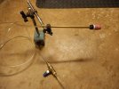
Haven't backpurged any actual plug welds yet as I'm still and will be for some time prepping all the donor parts. But the resultant holes from drilling the factory spots out have been and they're pretty much one in the same I guess.

Here's my rig. Just a plain dial indicator base. A Noga base would be ideal.

DSCN1267.JPG
 
Last edited:
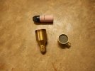
Different tips for different scenarios. Behind the SS screens are small discs of scotchbrite to act as diffusers.

DSCN1268.JPGDSCN1269.JPG
 
Last edited:
Generally guys plug weld with a MIG. It's a much easier and faster process than trying to TIG plug weld. Much less heat distortion. Two panels plug welded together should not really have any distortion. But if you are trying to use a TIG to plug weld then I guess it could happen. I don't know how you planish two panels plug welded together as it's not really done and kinda of impossible to actually planish (using a hammer and dolly) if we go by the accepted definition of planishing which is to stretch the metal. You can only really stretch one layer at a time.

No, I'm not trying to planish 2 panels plug welded together.

To be clear, what I'm doing is patching or filling the leftover holes from drilling out the factory spot welds so I can punch a smaller 1/4" hole to then make the final panel joining plug welds. And yes, while some of the factory spot welds are smaller than 11/32, many have this oblong shape to them, and I concluded 11/32 would be the best size to go with. Maybe it's on the larger end of the scale, but I didn't want to mangle the panels separating them due left-over spot weld remnants. Had a few where 11/32 was actually not big enough but was able to pop the 2 panels apart with a little persuasion.
 
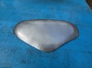
Plugged hole from drilled out spot weld that has been backpurged.
Note this is not a panel joining plug weld....sorry for the confusion if I was not clear.

DSCN0765.JPG
 
I typically use hotter welds, slightly more wire feed speed, and less time on the trigger. Hotter welds give you better flow out ie: flatter weld.
Ill try that, I am always overly paranoid about blowing a hole through it.
 
Thanks for that Robert. Yes, I've watched that and many others of yours several times over now. Where I get hung up the most is probably the last couple thousandths or so. Just always seems like the perimeter of the spot is always sunk down just a tad more that the surrounding material. And being as these are hole fills rather than plug welds, obviously I'm trying to save as much thickness as I can. I finished off about a dozen hole fills yesterday and found that I just have to go back and forth between roloc and hammering any waves down. Eventually it gets done. The final plug welds I have no intention on grinding, unless they look like Mt. Everest. But I plan to do many test runs to get my setting dialed in first.

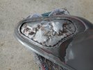
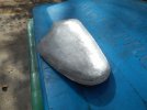
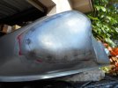
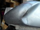
And while I'm here, I have to give a big thanks to you for both the posts of your work on this forum and your videos as they've been instrumental in giving me the confidence to tackle my first hammer form patch job. A neighbor brought me this motorcycle tank that had already been "repaired" once before. It was all body filled and painted, only problem was it leaked fuel from where several of the pull studs had been welded on in an attempt to straighten it. My first issue was welding where solder had been subsequently laid down over some of the pin holes and second was finding all the said pin holes.

So, I suggested just removing the entire crumpled section and I'll take a stab at pounding at a patch. Told him this was my first attempt at such a thing and I wouldn't cut any holes in the tank until he sees the patch first and gives the ok.

Since pics rule:

DSCN1209.JPGDSCN1212.JPGDSCN1215.JPGDSCN1220.JPGDSCN1244.JPG

It's a far cry from perfect, but miles better than it was and the owner was super stoked. Just would've been nice to have been able to planish it out after welding, but simply not possible without splitting the seam.

Thanks again Robert.

Rusty
 
Ill try that, I am always overly paranoid about blowing a hole through it.
If you blow a hole, it's because there is not enough filler wire going in for the amount of heat applied, and as a result the parent metal burns back. more feed speed, less time on the trigger pull. Get it out of your head that the heat setting control knob is the only way to control the heat.
 
Where I get hung up the most is probably the last couple thousandths or so. Just always seems like the perimeter of the spot is always sunk down just a tad more that the surrounding material.

If you can see that the weld is depressed, try bumping it up/out from the back side where you won't see it as readily, then dress it again. Well done on the hammer form patch, looks like it belongs there...

On your thickness issues, ideally you want to keep the panel thicknesses as close to parent metal as possible. Any excessively thin areas would be more prone to deformation due to the inherent stresses that the panel sees, ie: body flex as one example. Not that I've broken out the micrometer, but some dressing of the weld will get you into the metal on either side. You kinda know when you've been sitting there too long. Going from .0355 to .0325 is only losing .003, that's not bad at all. Losing .010 is like having 18 ga right next to 20 gauge. I fear that may be unstable IF it was in a high stress area. If it isn't then play it by ear.

Good info. Being still relatively green to sheet metal work, I'll do spot checks every now and then with a micrometer just to see where I'm at. And even that is somewhat moot, to a degree, knowing the mic is only reading the thickest point within the 1/4" diameter contact pads. But it's good to know that 3 thou of loss isn't bad. I kind of figured there had to be some amount of acceptable loss, just did not know how much. And yes, striving for zero loss is always the goal.

This is what having OCD in the genes and working in a machine shop will do to you....it's destroyed my woodworking skills, lol.
 
Back
Top