You are using an out of date browser. It may not display this or other websites correctly.
You should upgrade or use an alternative browser.
You should upgrade or use an alternative browser.
Wagon Progress
- Thread starter MP&C
- Start date
MP&C
Member
Thanks Chad!
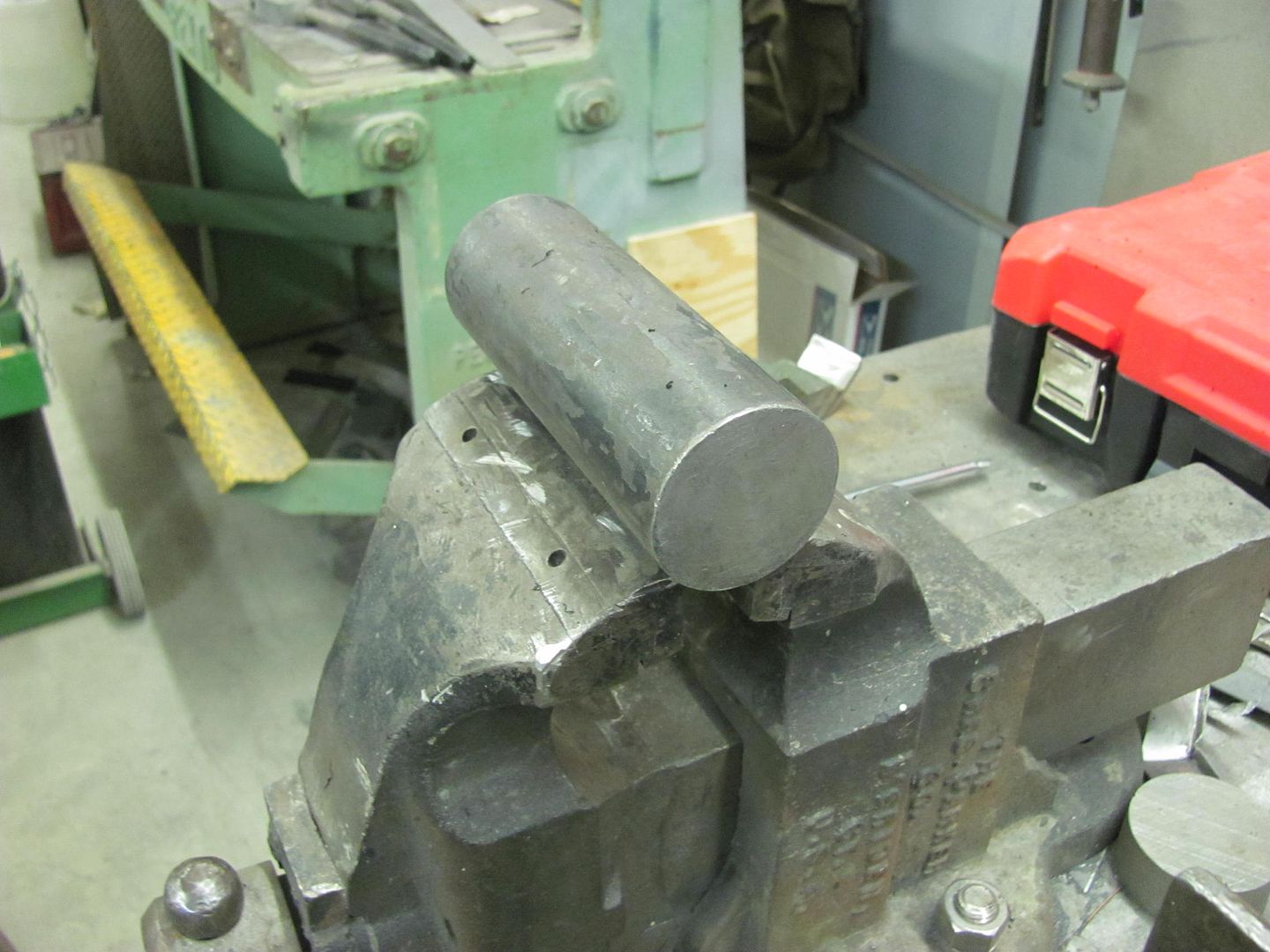
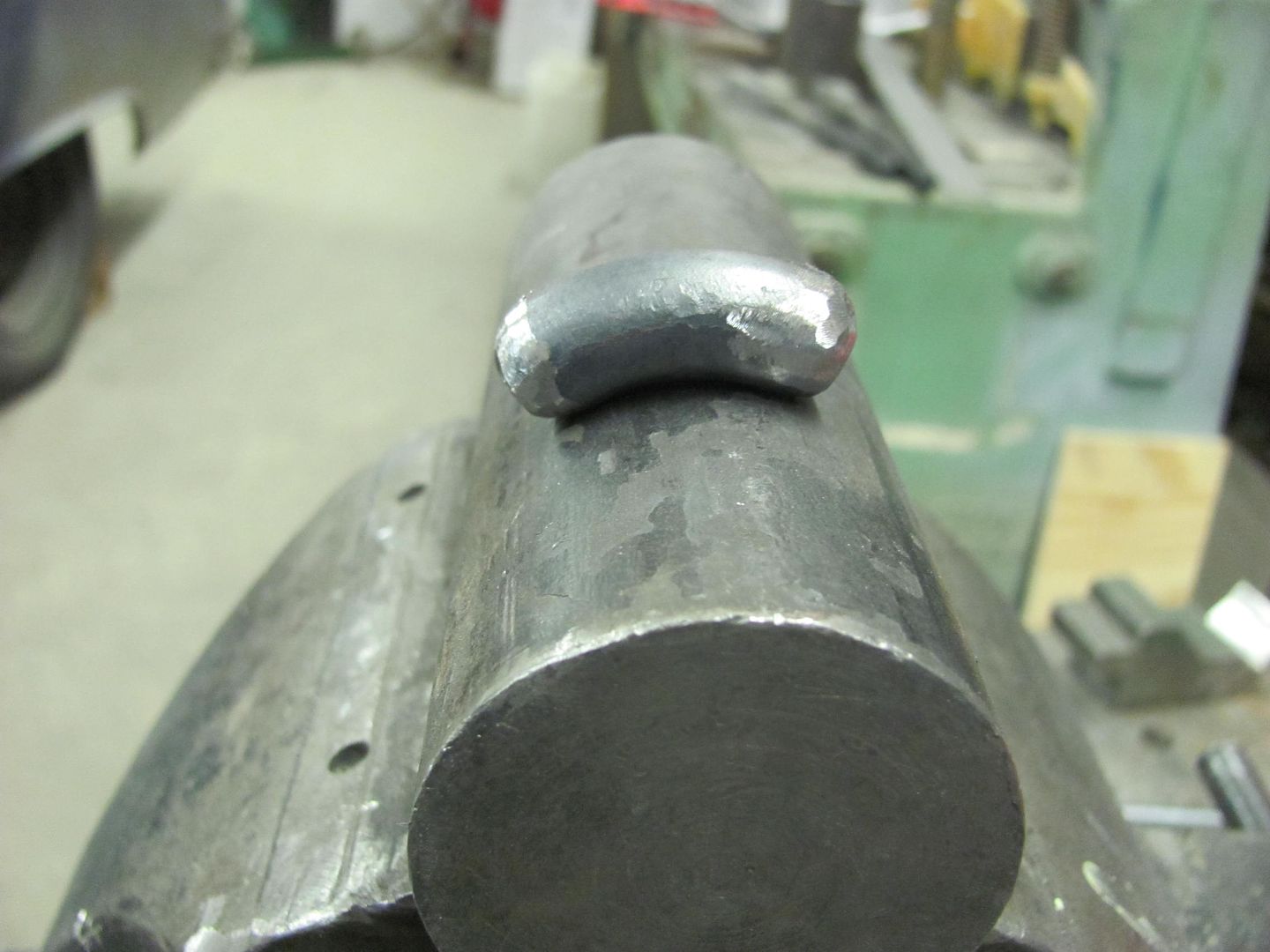
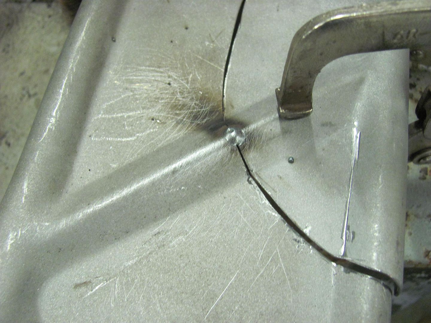
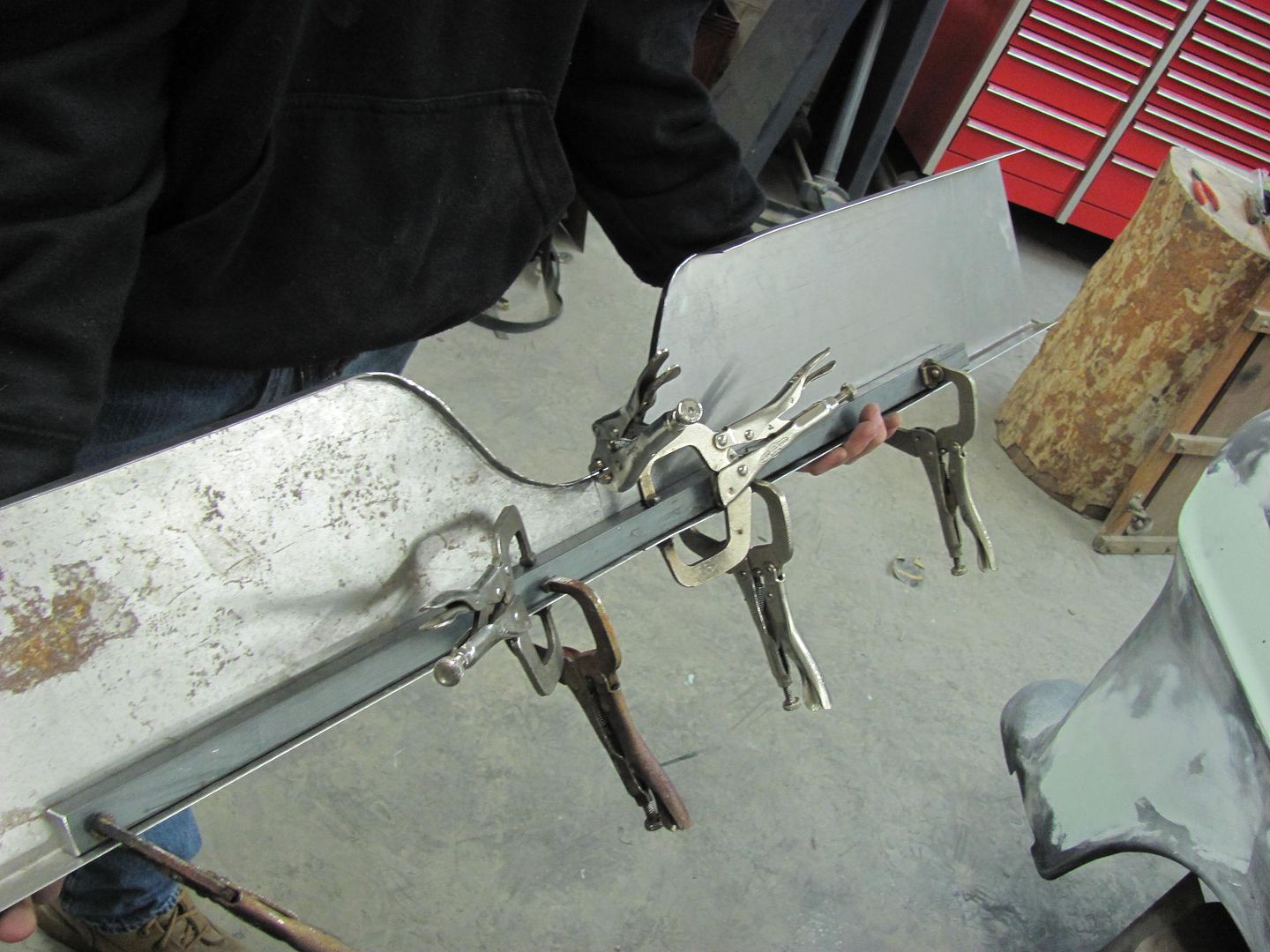
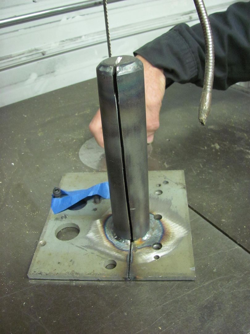
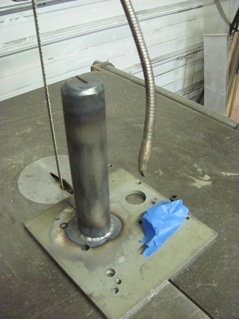
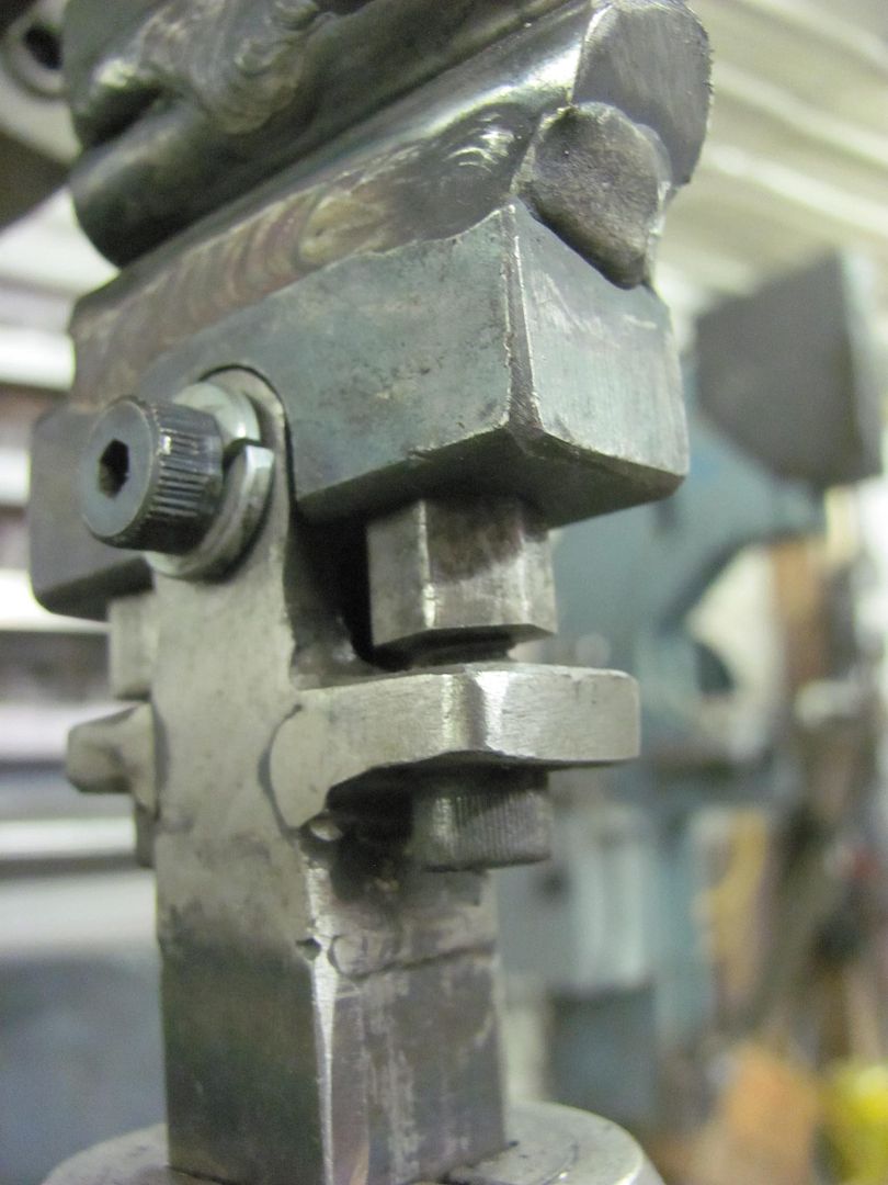
Today Kyle needed to start some welding on the hood brace, so while he was getting set up with the welder, I started making him an anvil that he could use to planish the weld dots inside the radius voids..
Heat applied...
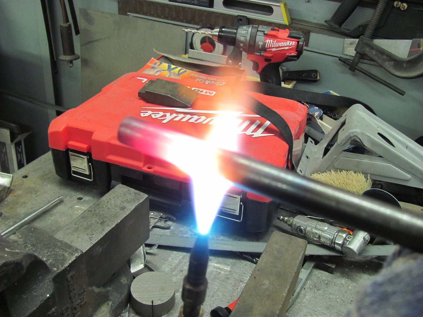

Kyle's first job at welding sheet metal, he's a quick learner. He did have a couple spots that didn't like the heat and blew a hole, but he did a real nice job in getting those fixed as well.
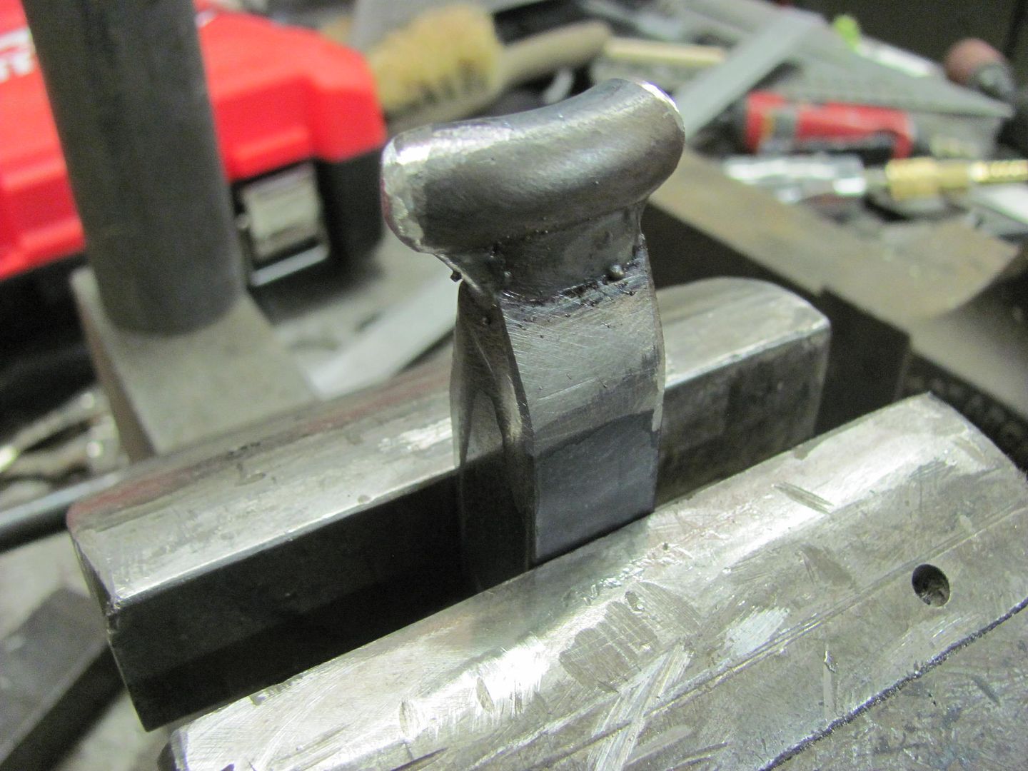
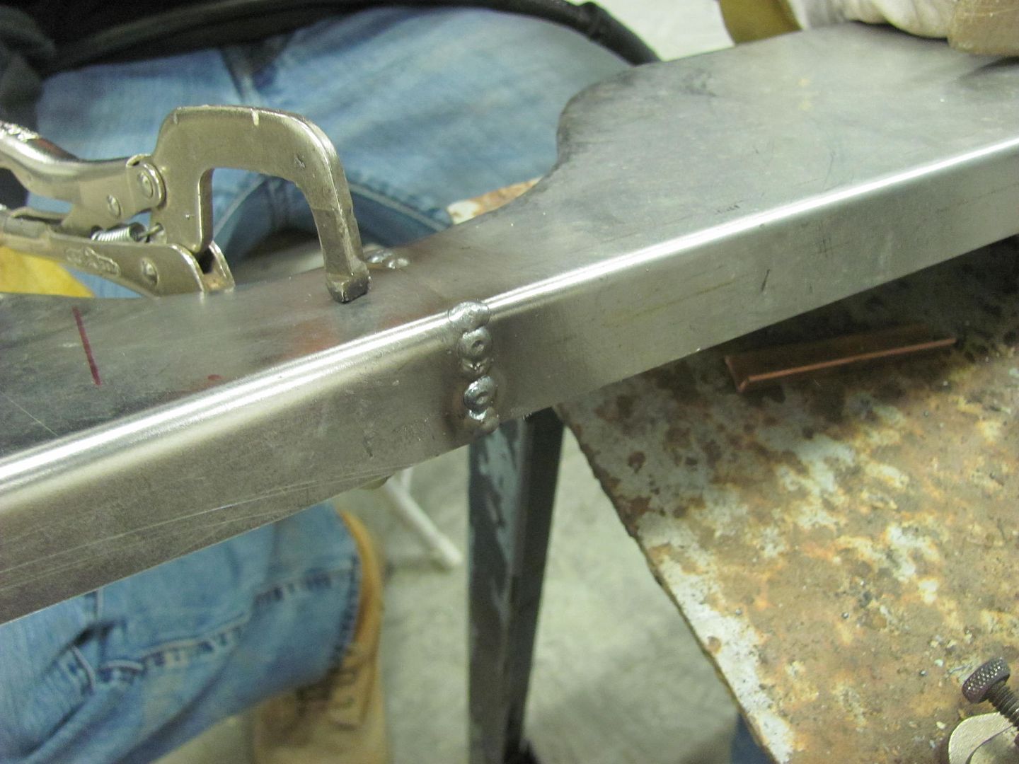
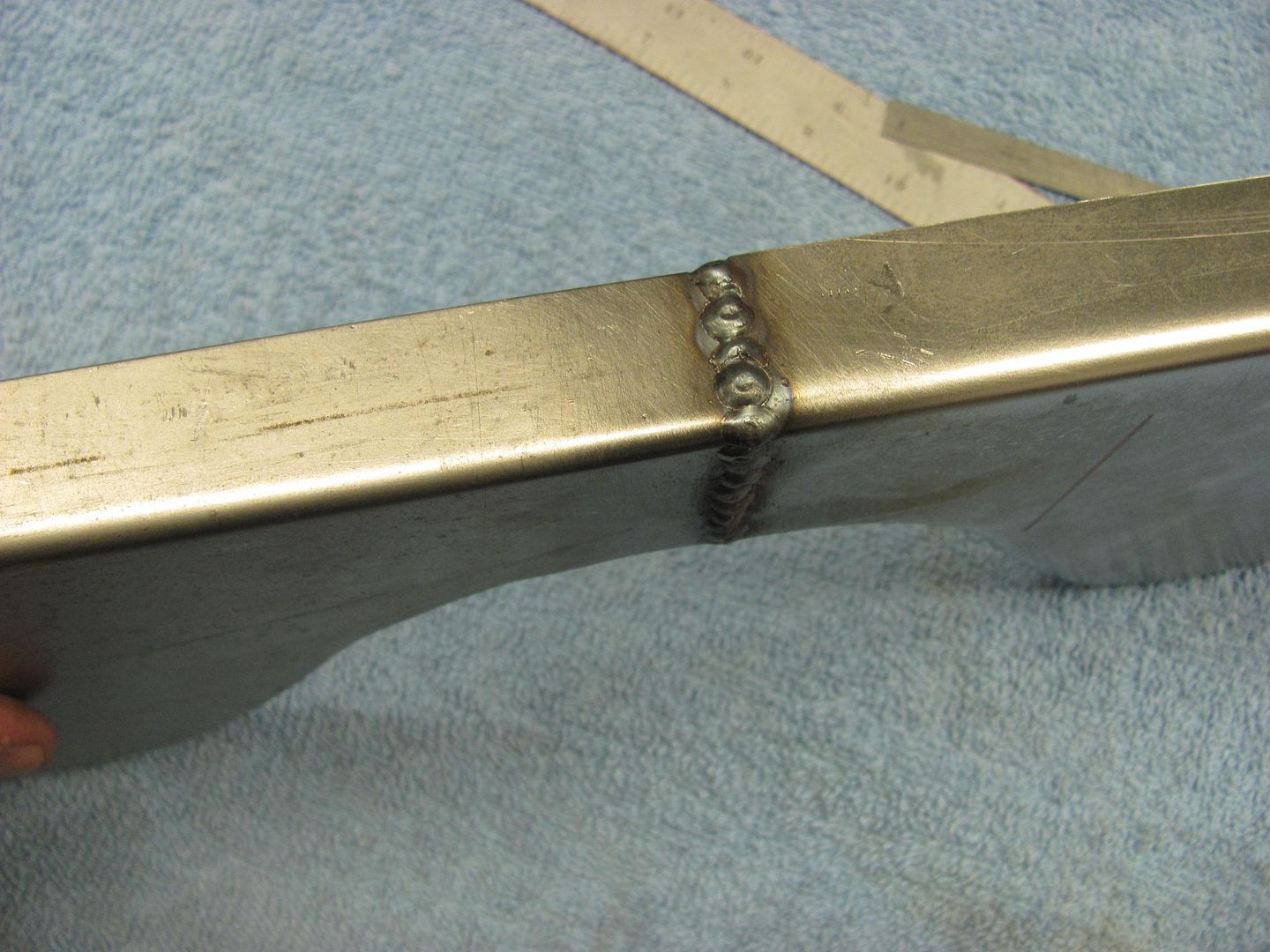
Planishing weld dots on the new "anvil"..
Full weld penetration...
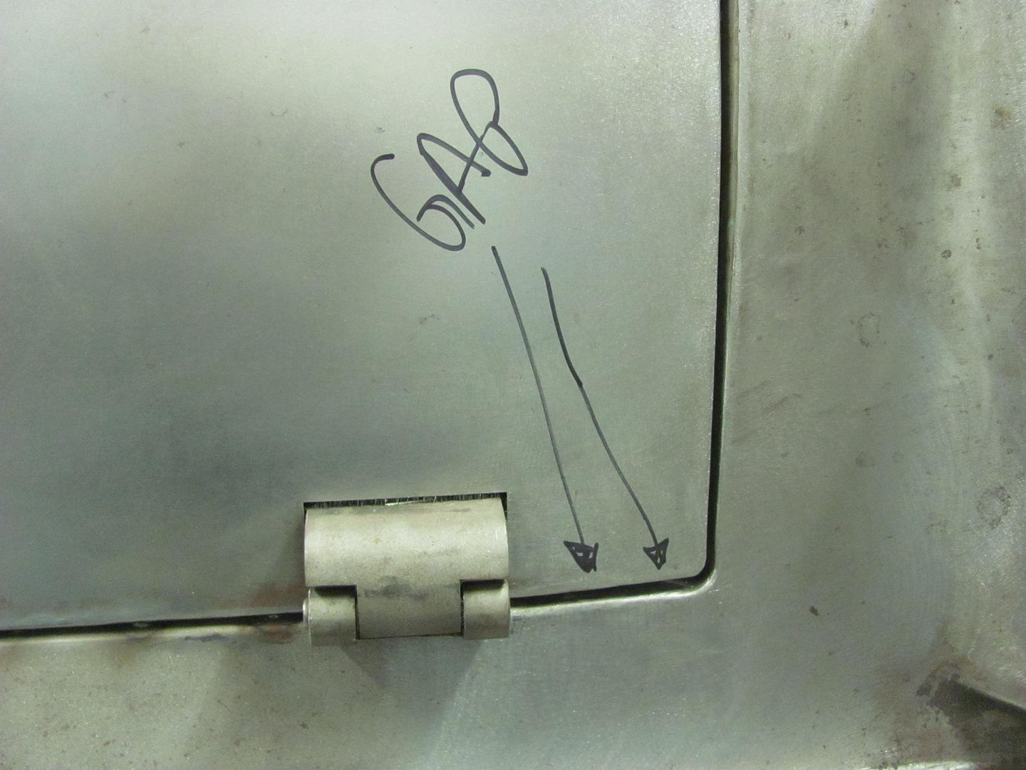
While he welded away, I turned my attention to the front end. The passenger door had a bit of a tight spot to the rear edge of the fender while opening.. Using a hack saw blade as a "feeler gauge", it was tight in one area. To help out the situation, time for another tool. I have a dent puller with a small pair of vise grips permanently attached, so we just need an adapter kit...
This was some leftover square tubing scraps...
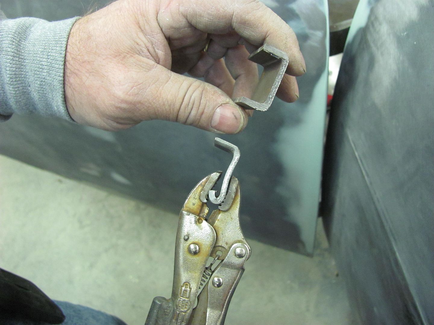
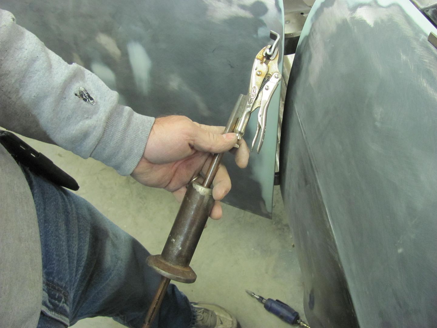
In use..
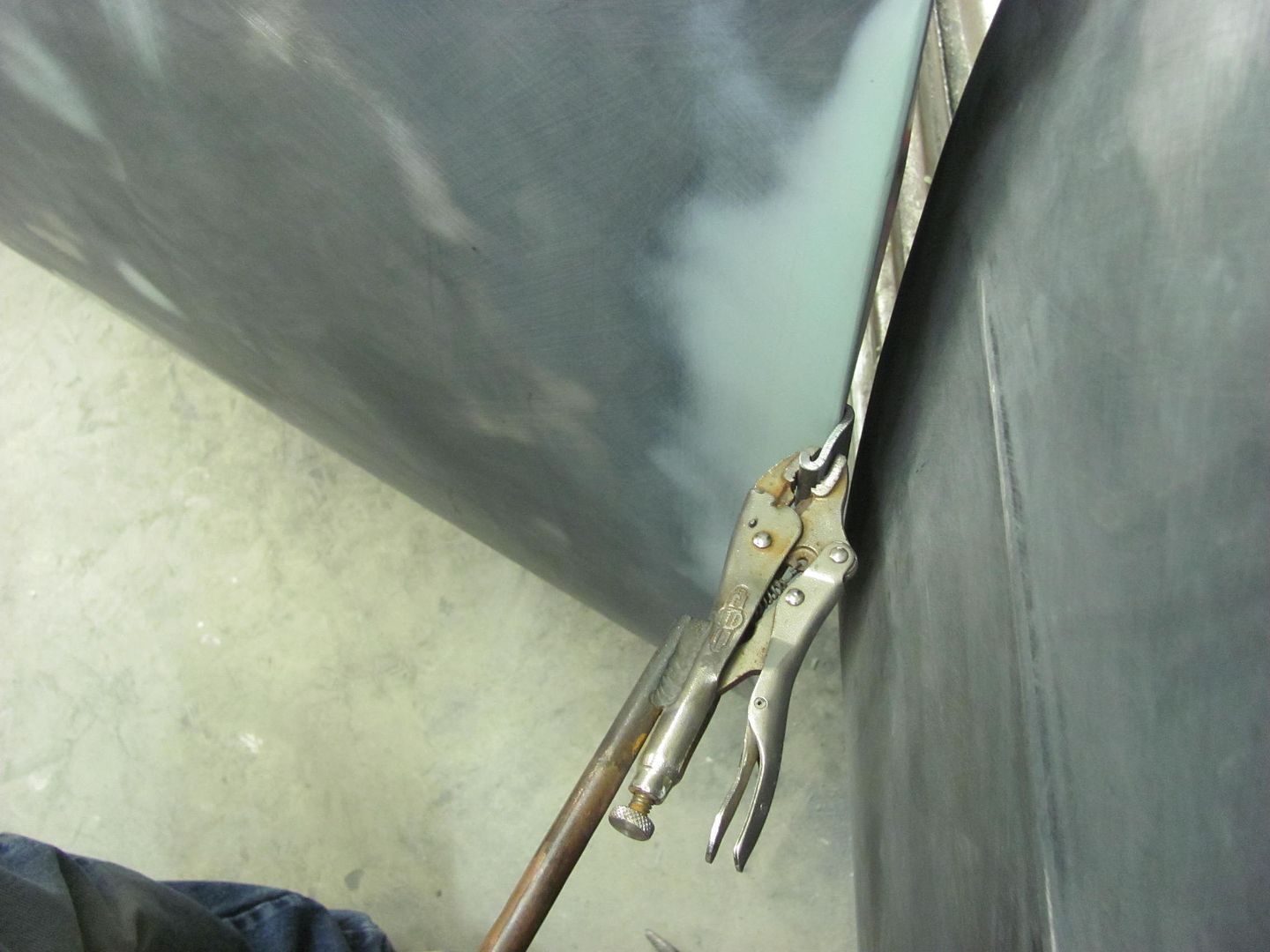
After the pulling effort, the tight gap was well over two HSB thicknesses.
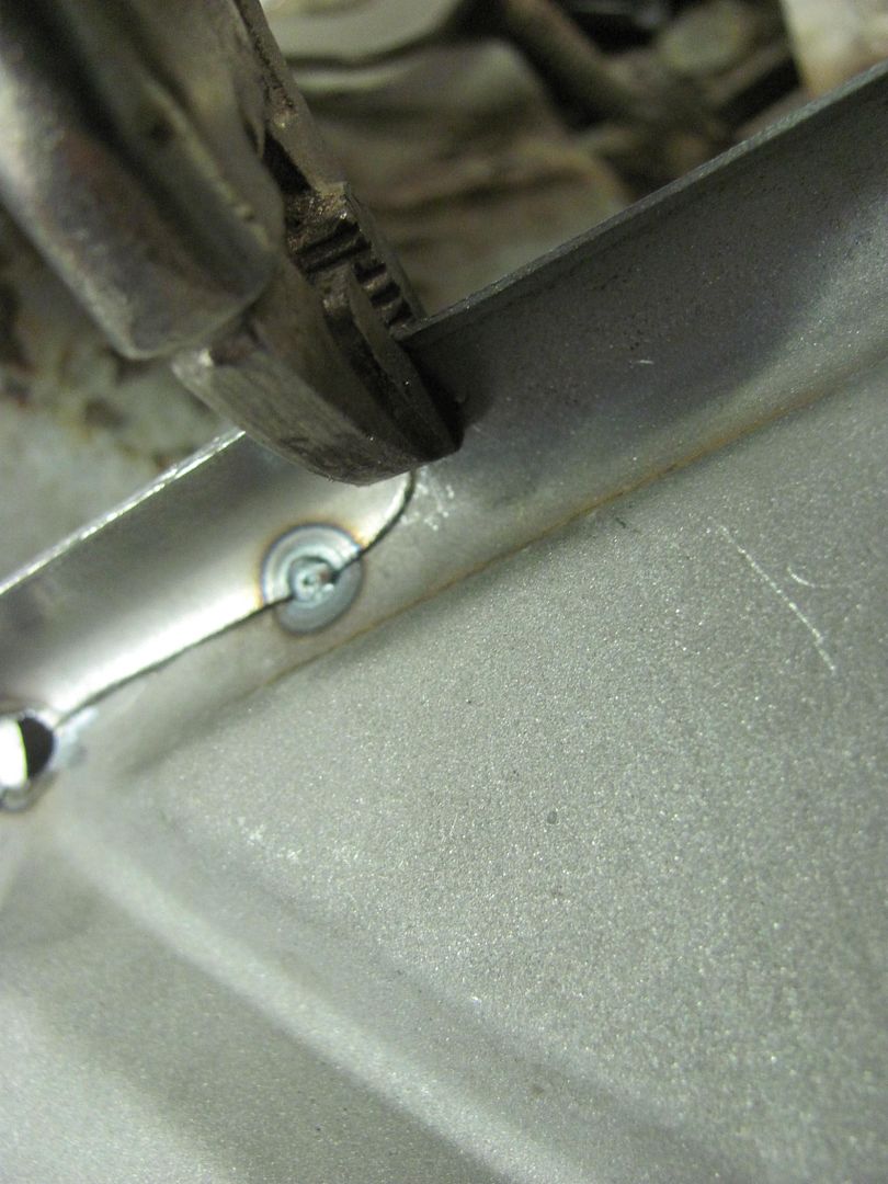
Moving on to other fender fitment, the bottom edge of the fender was higher than the adjacent rocker. Any adjustment was futile as the bolt was at the bottom of the adjustment hole. Time for some die grinder action to bring the hole downward and also flatten the bottom edge of the hole so any movement forward or backward doesn't push the bolt upward..... This was done on both fenders..
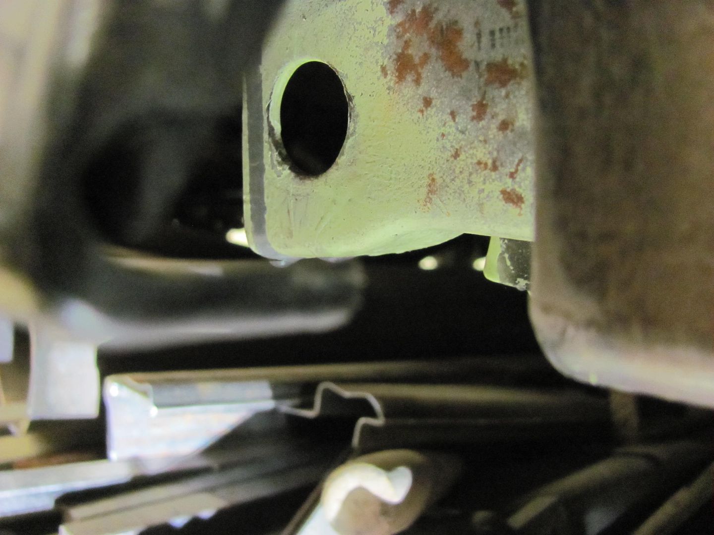
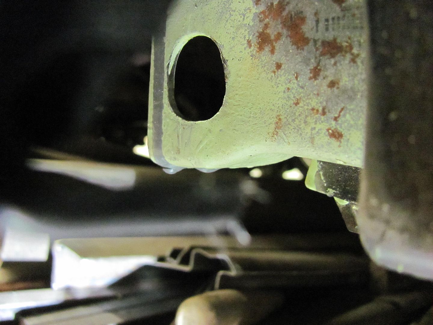
Test fit shows much better alignment.. This may be why the 57 went to a square hole..
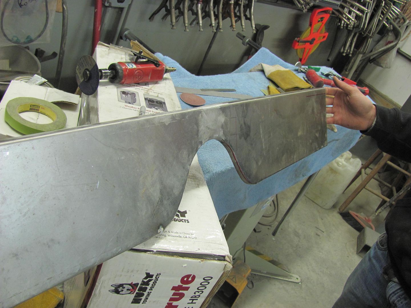
Kyle done with his welding on the center patch, just needs to be dressed with the sanding disc. We'll save that for after the other patch gets welded in place..
Front:
Rear:
And I was also busy making more dust... Can't wait for springtime and the leaf blower")
Today Kyle needed to start some welding on the hood brace, so while he was getting set up with the welder, I started making him an anvil that he could use to planish the weld dots inside the radius voids..
Heat applied...
Kyle's first job at welding sheet metal, he's a quick learner. He did have a couple spots that didn't like the heat and blew a hole, but he did a real nice job in getting those fixed as well.
Planishing weld dots on the new "anvil"..
Full weld penetration...
While he welded away, I turned my attention to the front end. The passenger door had a bit of a tight spot to the rear edge of the fender while opening.. Using a hack saw blade as a "feeler gauge", it was tight in one area. To help out the situation, time for another tool. I have a dent puller with a small pair of vise grips permanently attached, so we just need an adapter kit...
This was some leftover square tubing scraps...
In use..
After the pulling effort, the tight gap was well over two HSB thicknesses.
Moving on to other fender fitment, the bottom edge of the fender was higher than the adjacent rocker. Any adjustment was futile as the bolt was at the bottom of the adjustment hole. Time for some die grinder action to bring the hole downward and also flatten the bottom edge of the hole so any movement forward or backward doesn't push the bolt upward..... This was done on both fenders..
Test fit shows much better alignment.. This may be why the 57 went to a square hole..
Kyle done with his welding on the center patch, just needs to be dressed with the sanding disc. We'll save that for after the other patch gets welded in place..
Front:
Rear:
And I was also busy making more dust... Can't wait for springtime and the leaf blower
MP&C
Member
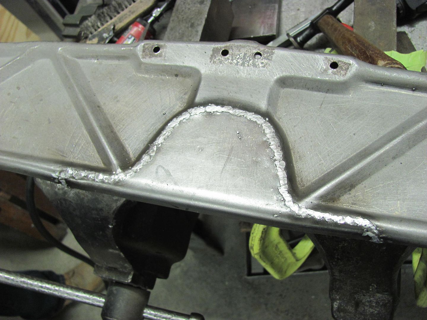
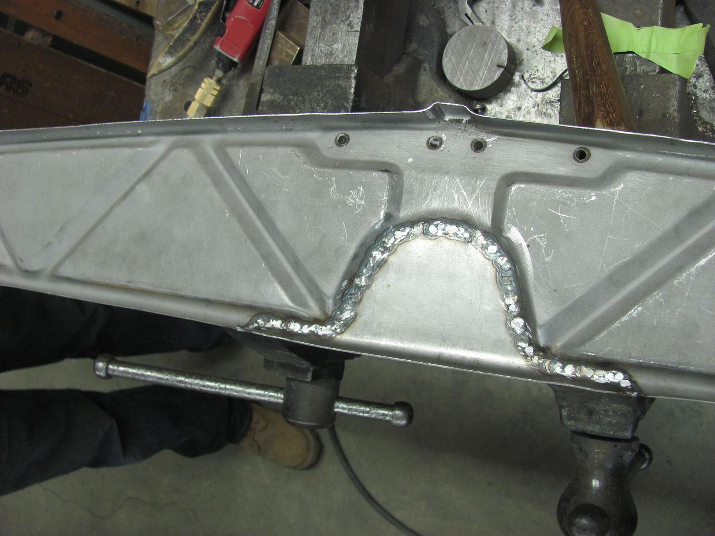
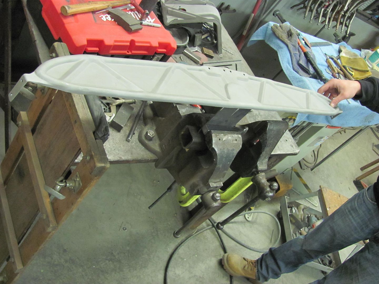
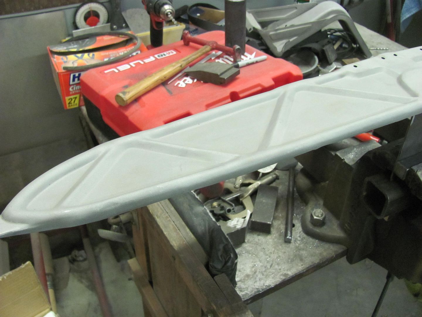
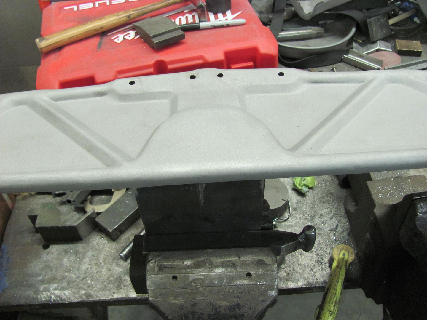
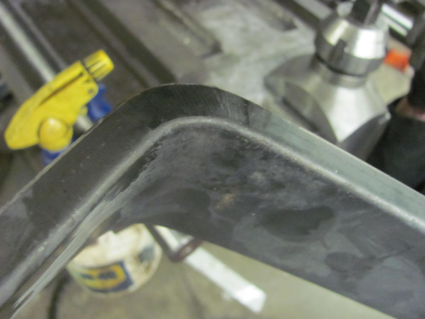
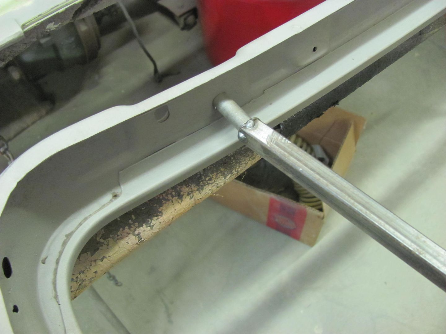
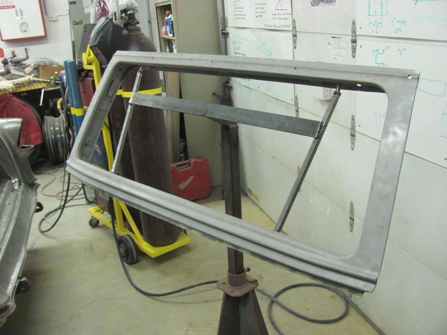
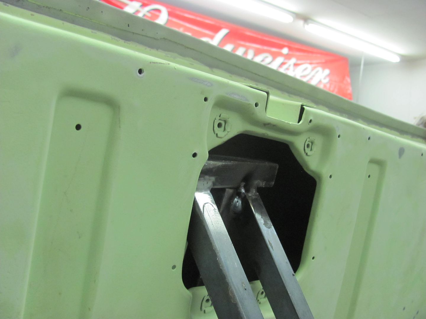
Kyle finishing up on the hood brace....
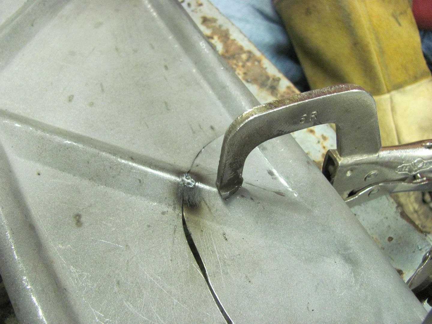
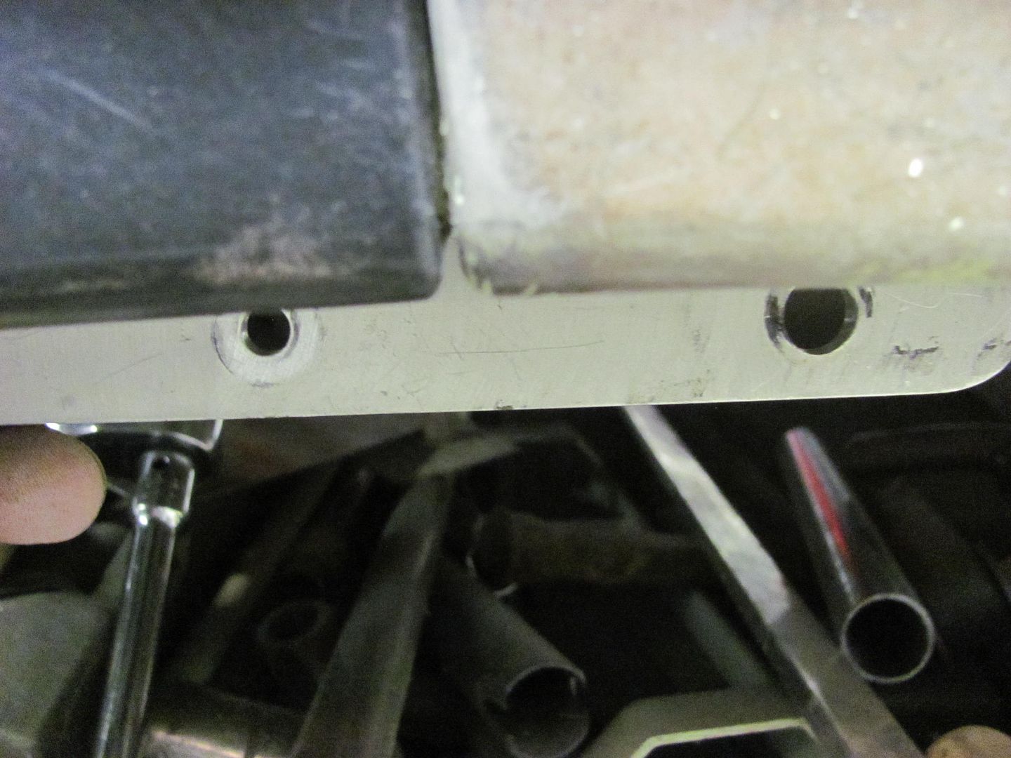
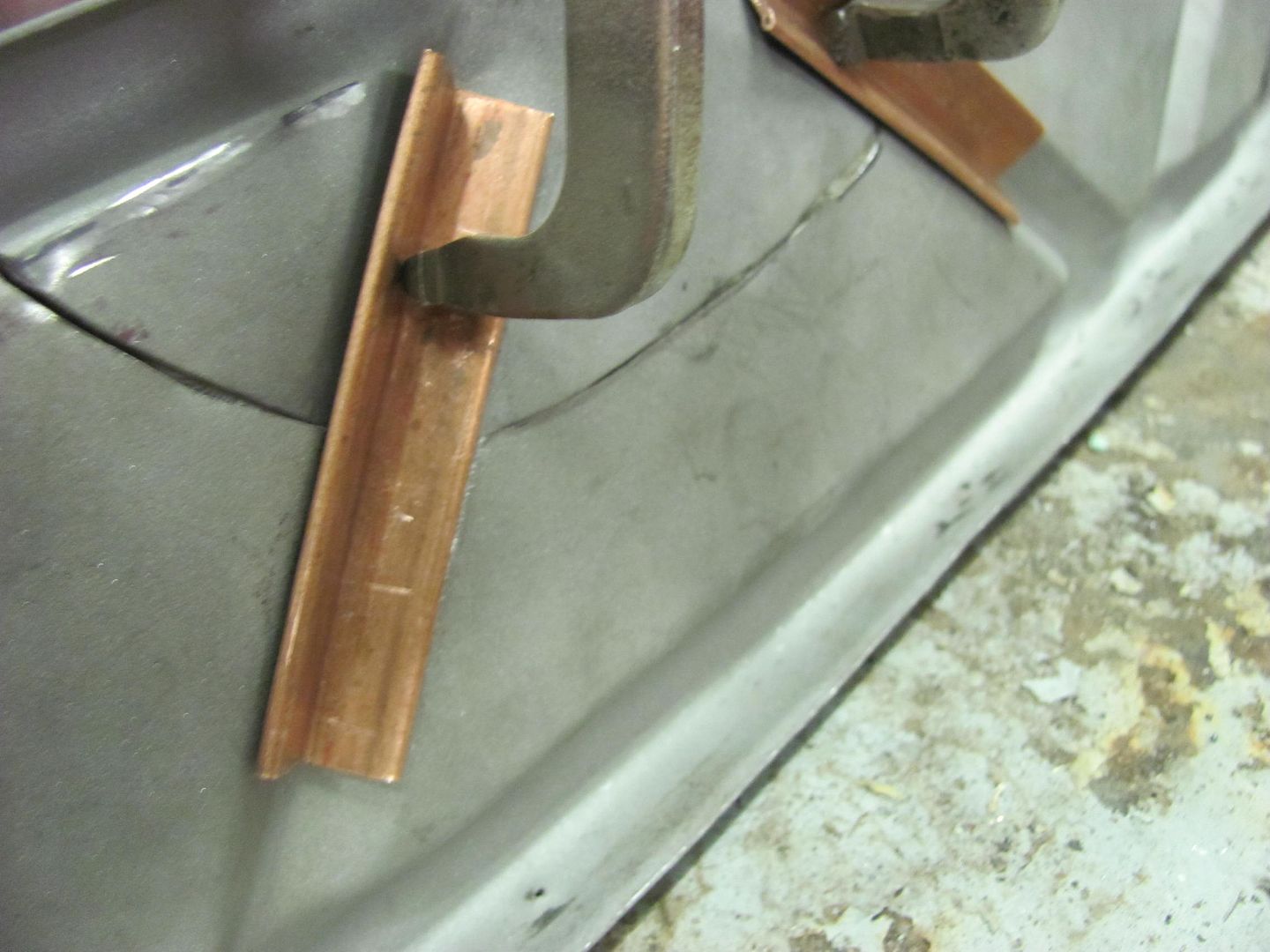
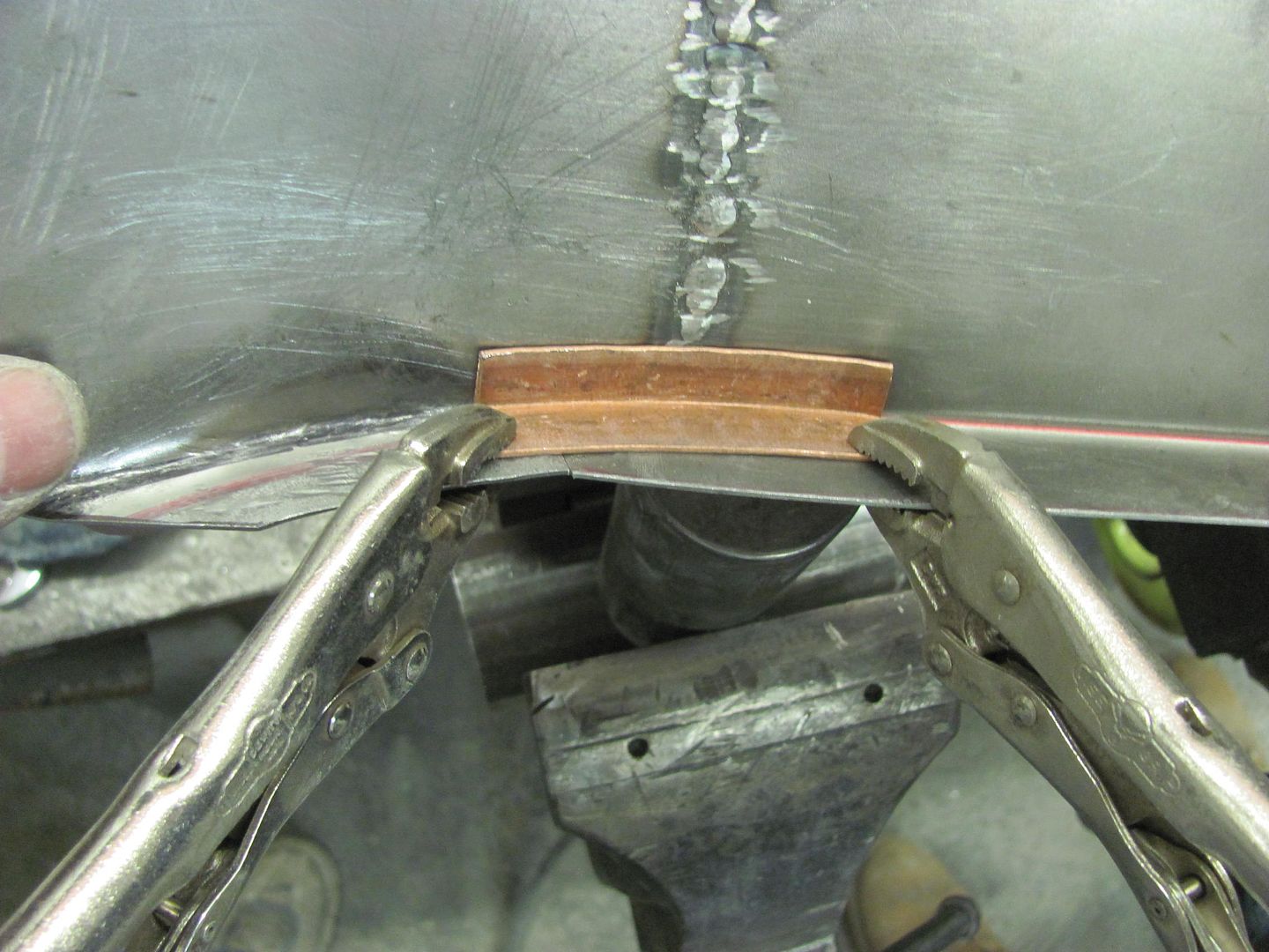
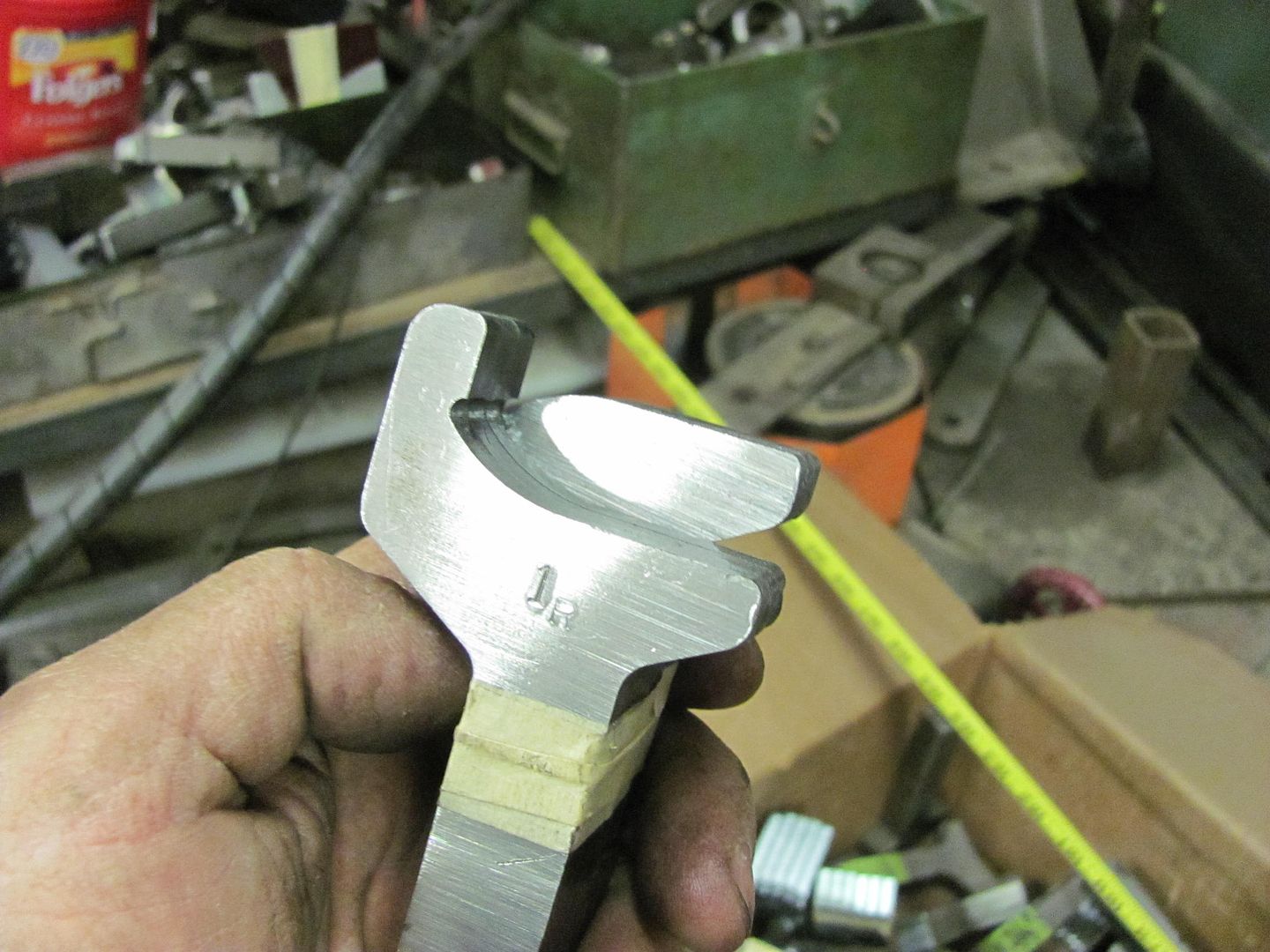
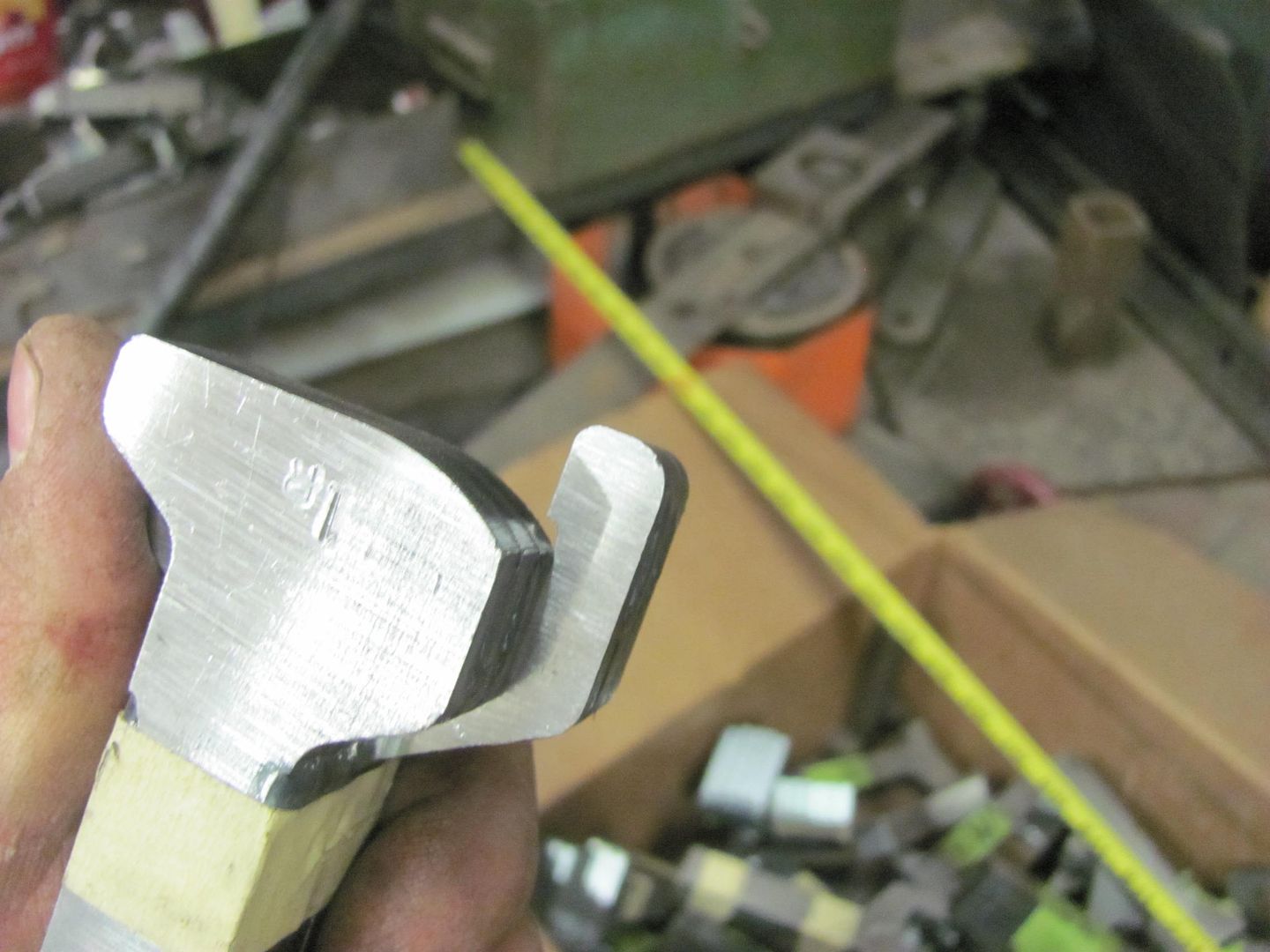
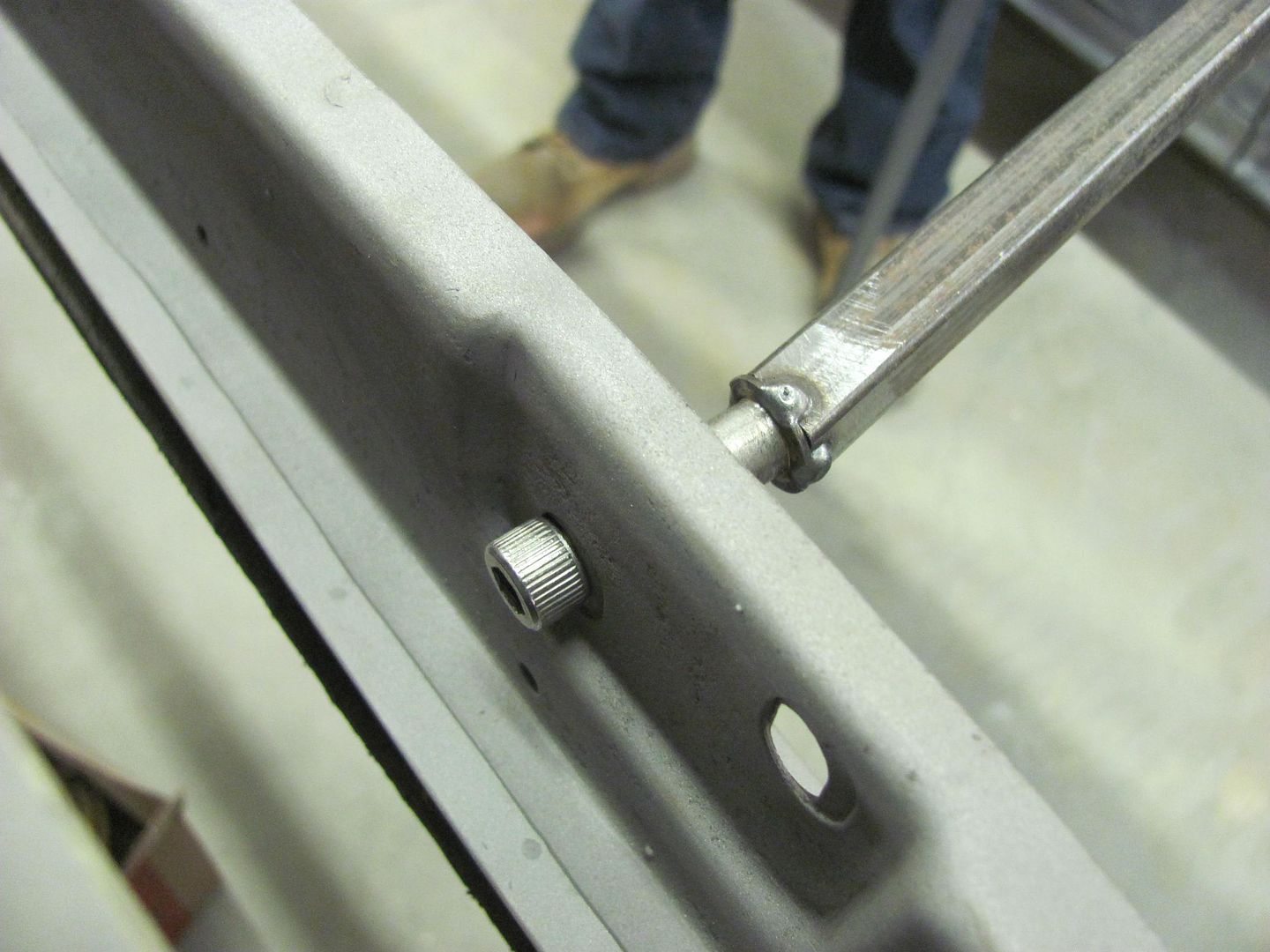
Because he had gaps to contend with, we used some copper to insure less chance of blow outs. A piece of 1/2" copper pipe was flattened and bent in the press brake to make a fitted backing for the vee bead detail..
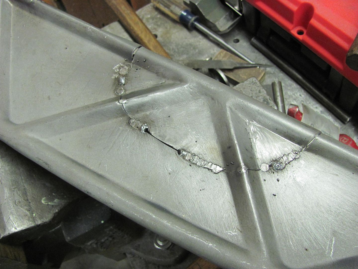
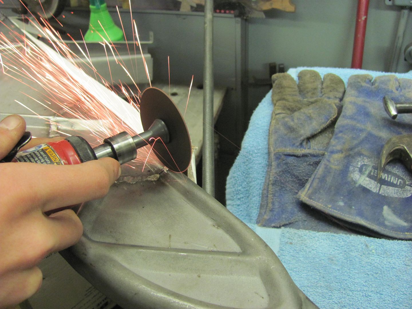
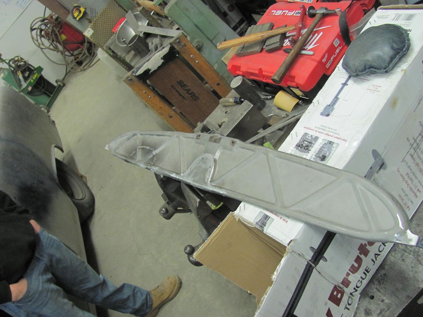
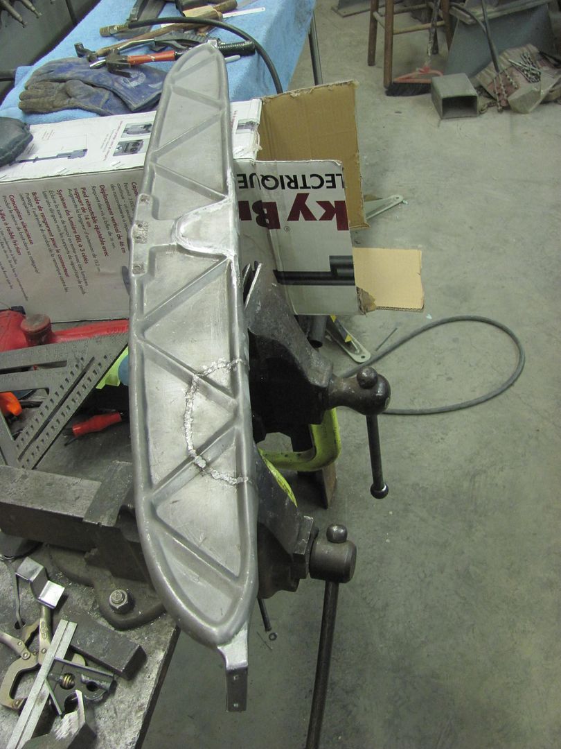
Just a bit of work with the sander and this part should be done. Like the new look without all the gaping holes..
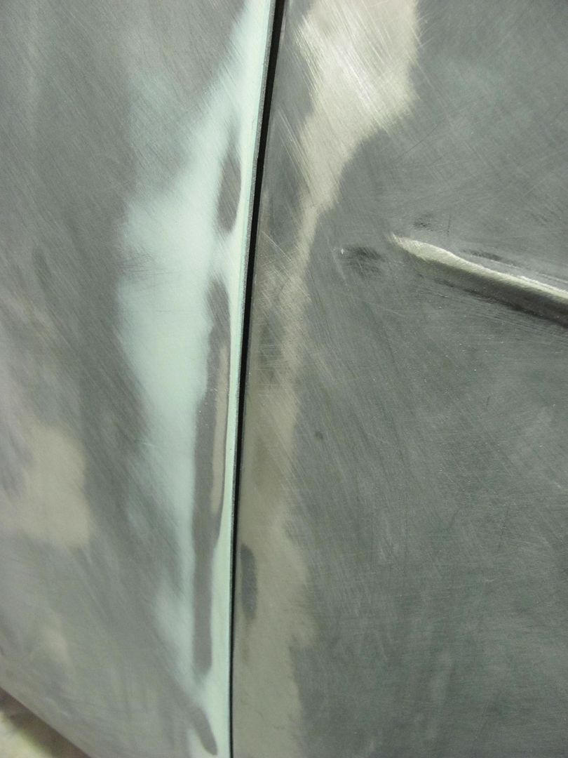
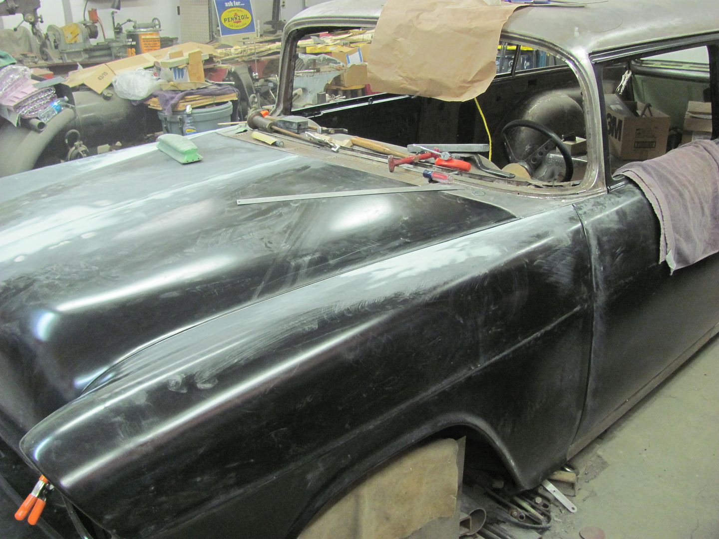
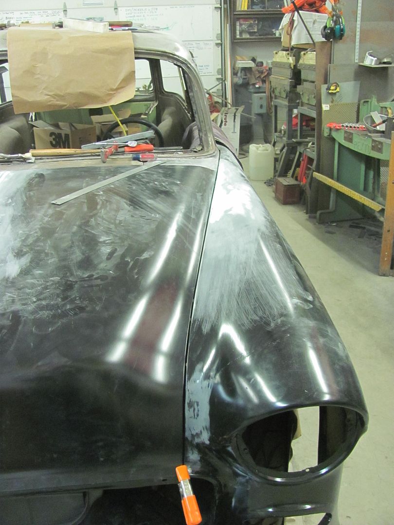
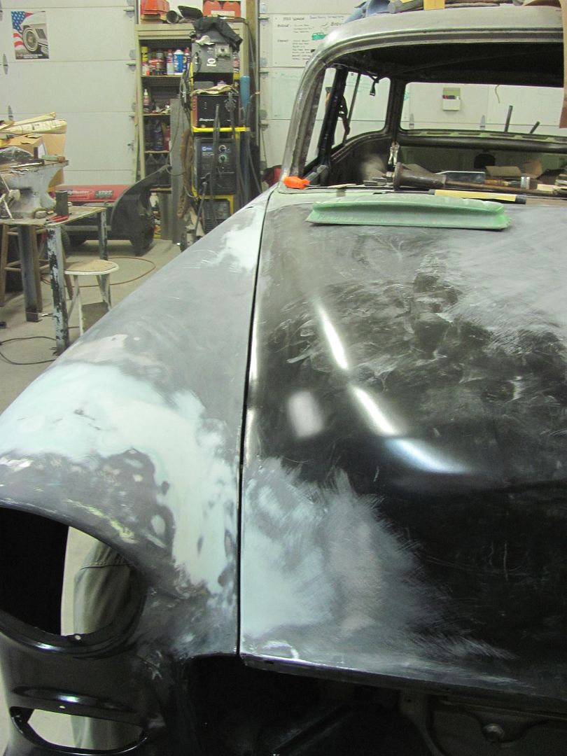
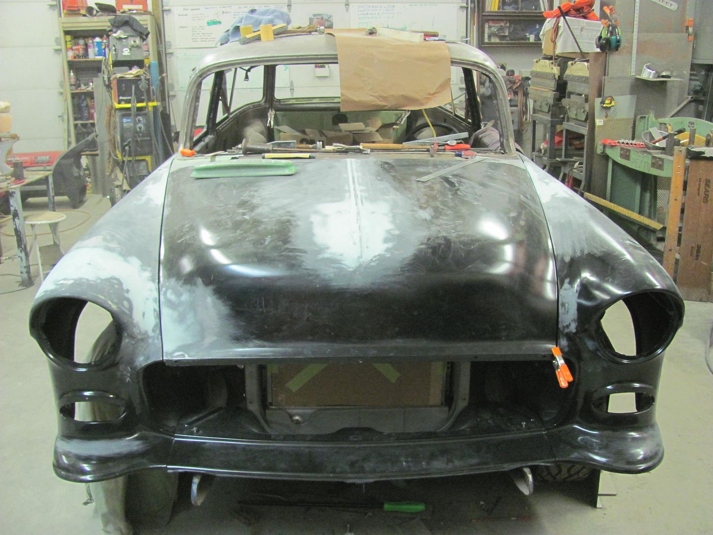
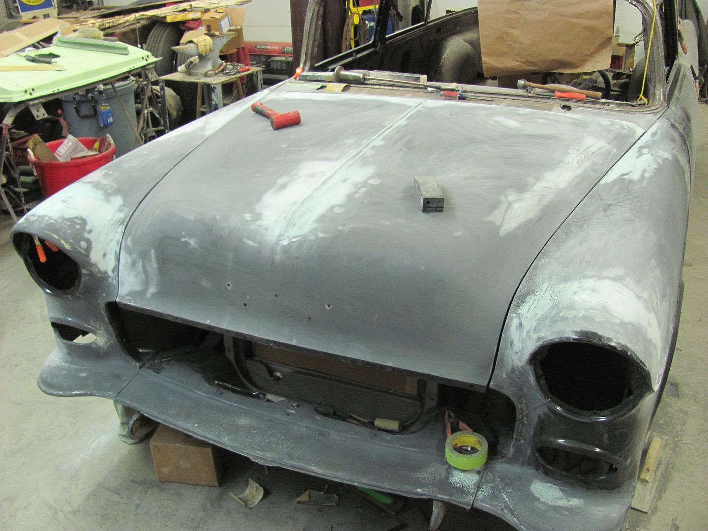
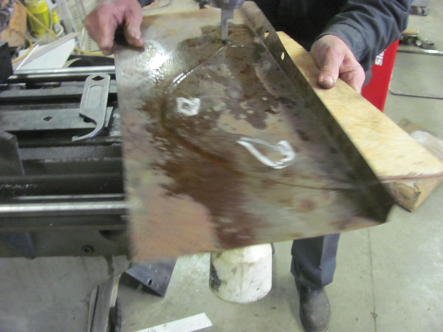
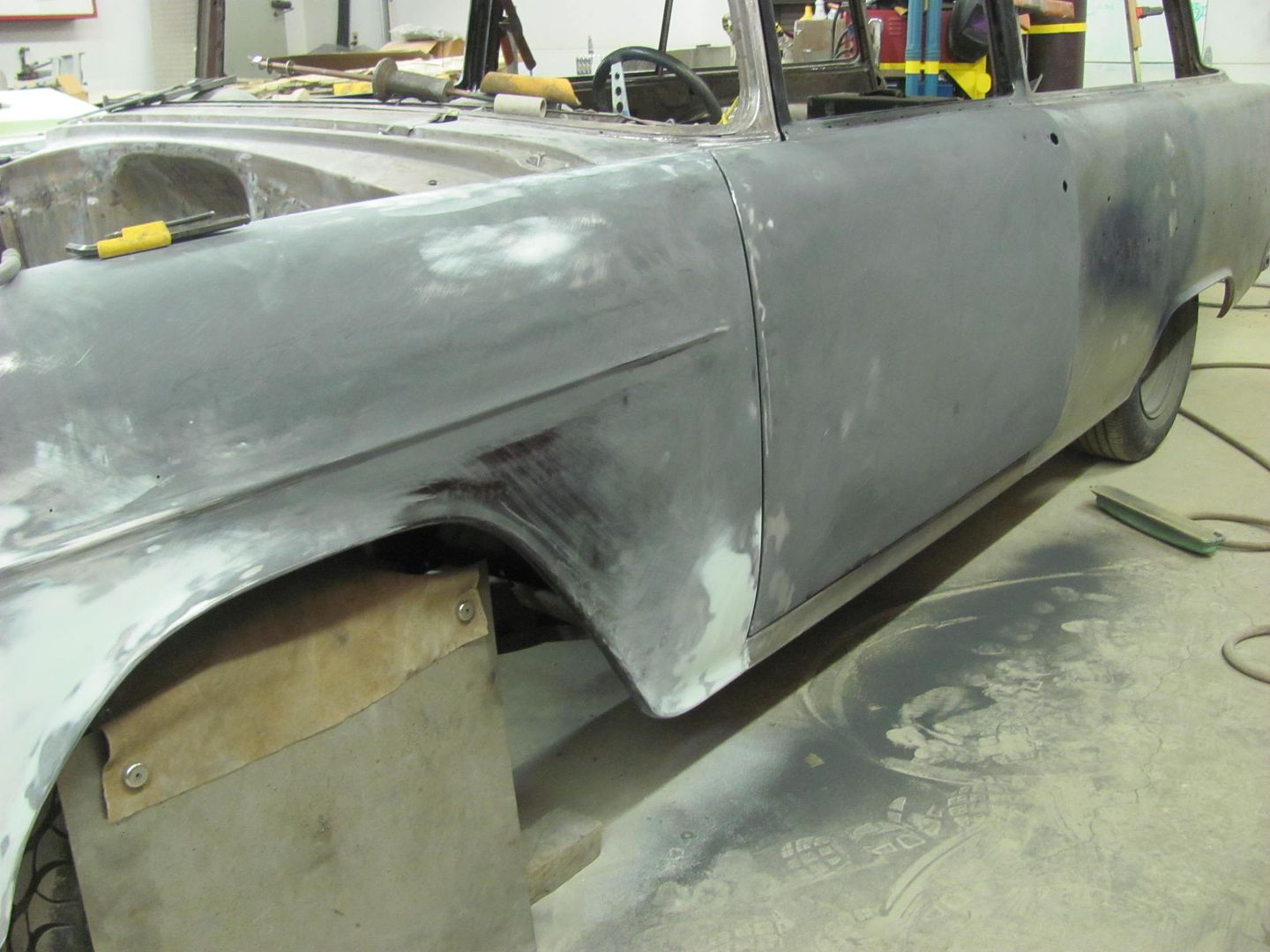
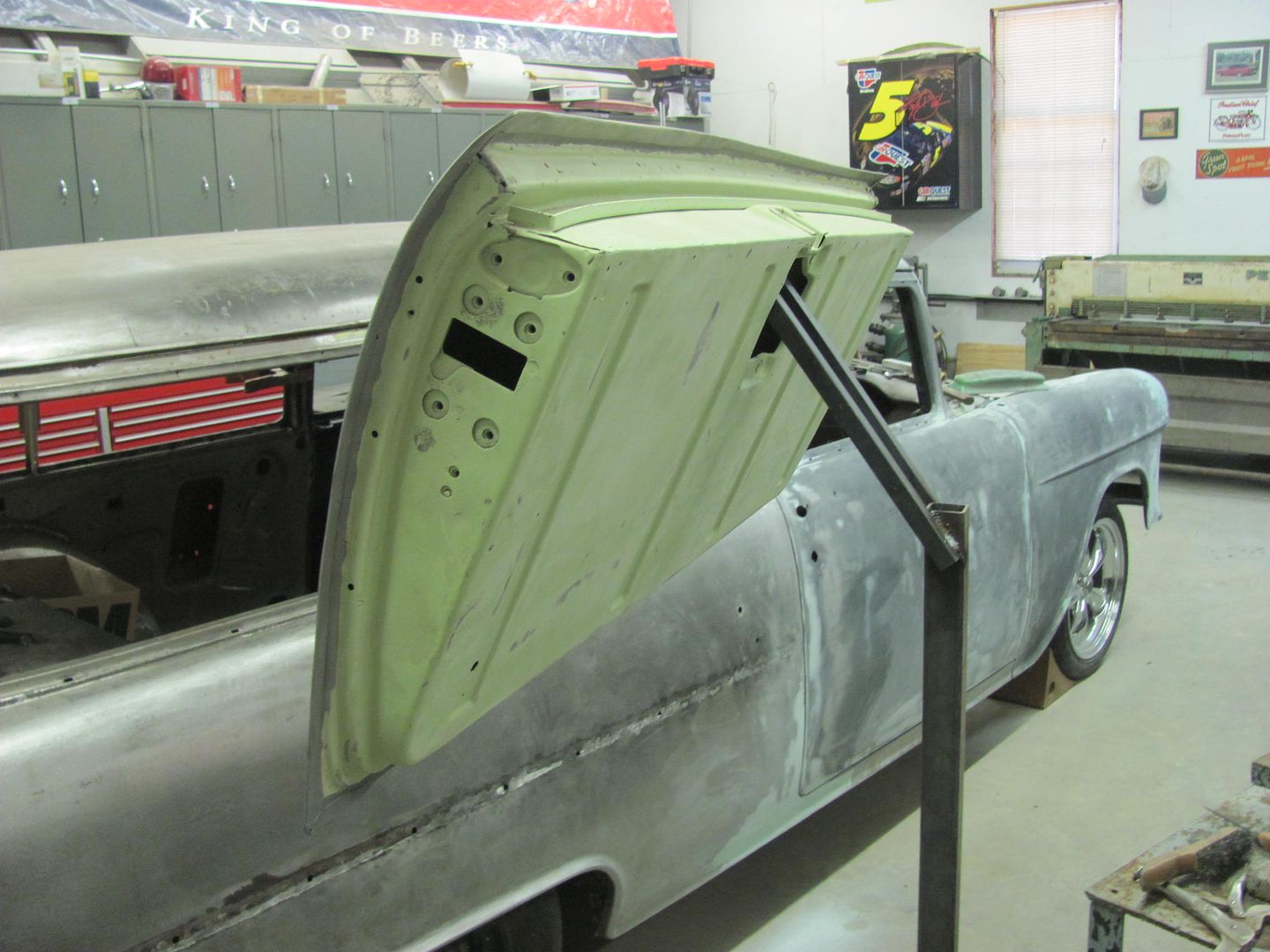
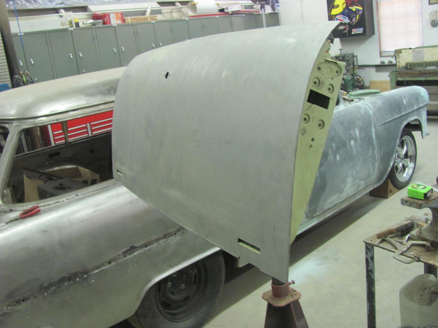
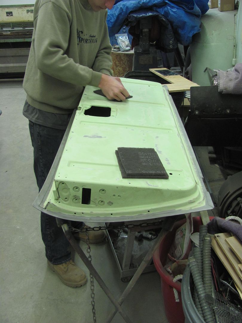
Meanwhile, I continued to make dust. Here's a good view of the built in "guide coat" feature of the SPI. Blocking on the top of the hood shows a low spot.....
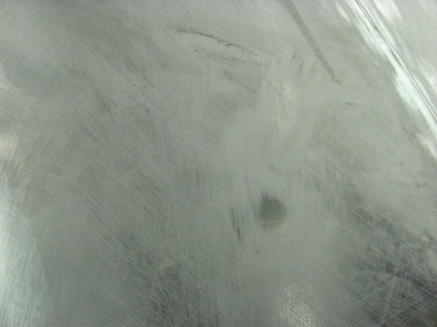
And with just a couple scuffs from the bottom, the low shows up there as well
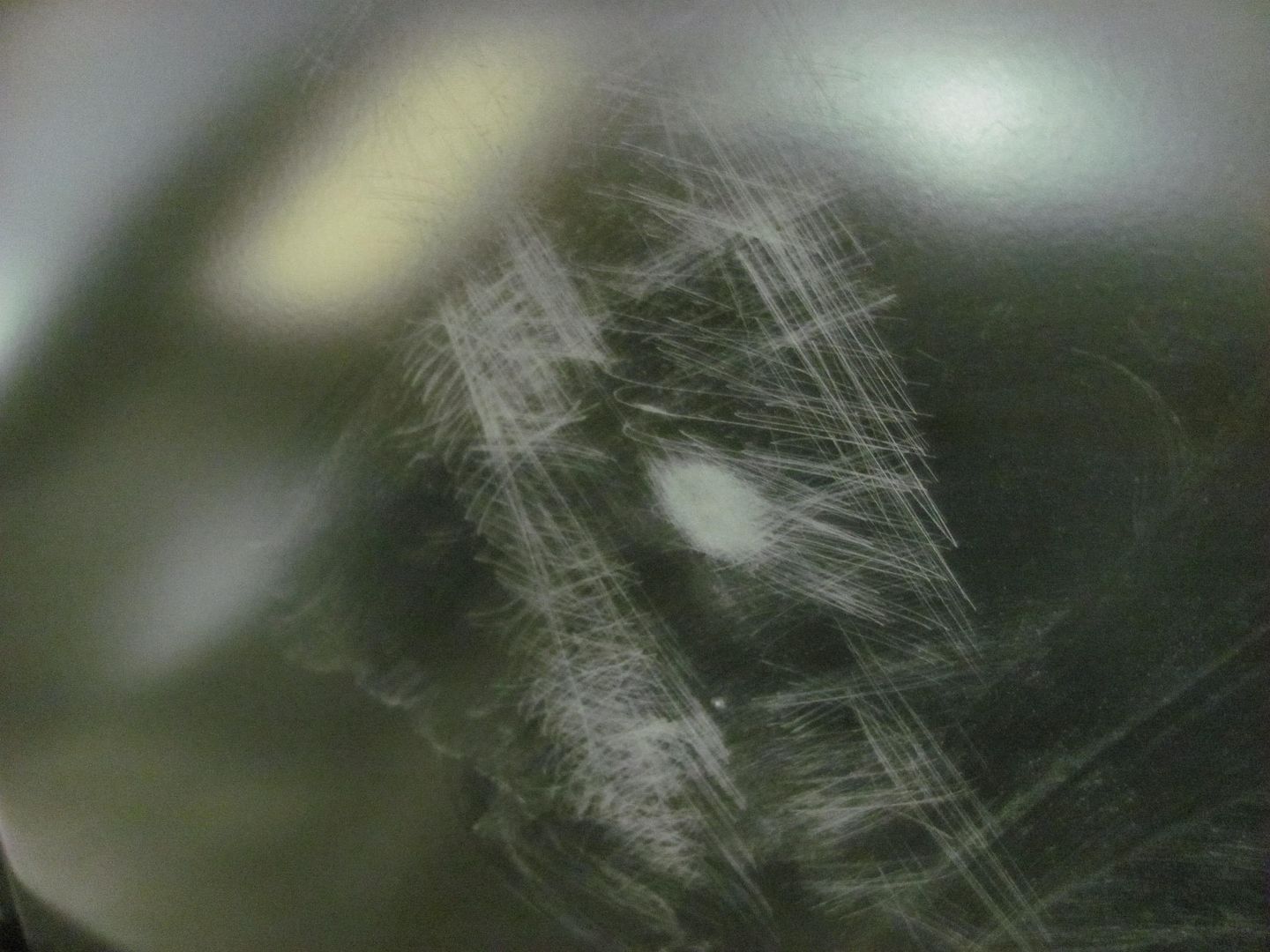
Just a few bumps with the hammer from the bottom into the small shot bag on top and the low is gone.
And the rest looks pretty much the same other than the piles of dust on the floor moving around..
Because he had gaps to contend with, we used some copper to insure less chance of blow outs. A piece of 1/2" copper pipe was flattened and bent in the press brake to make a fitted backing for the vee bead detail..
Just a bit of work with the sander and this part should be done. Like the new look without all the gaping holes..
Meanwhile, I continued to make dust. Here's a good view of the built in "guide coat" feature of the SPI. Blocking on the top of the hood shows a low spot.....
And with just a couple scuffs from the bottom, the low shows up there as well
Just a few bumps with the hammer from the bottom into the small shot bag on top and the low is gone.
And the rest looks pretty much the same other than the piles of dust on the floor moving around..
MP&C
Member
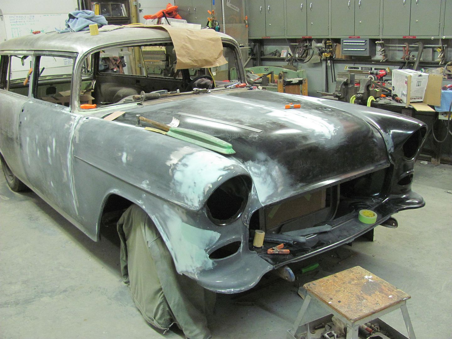
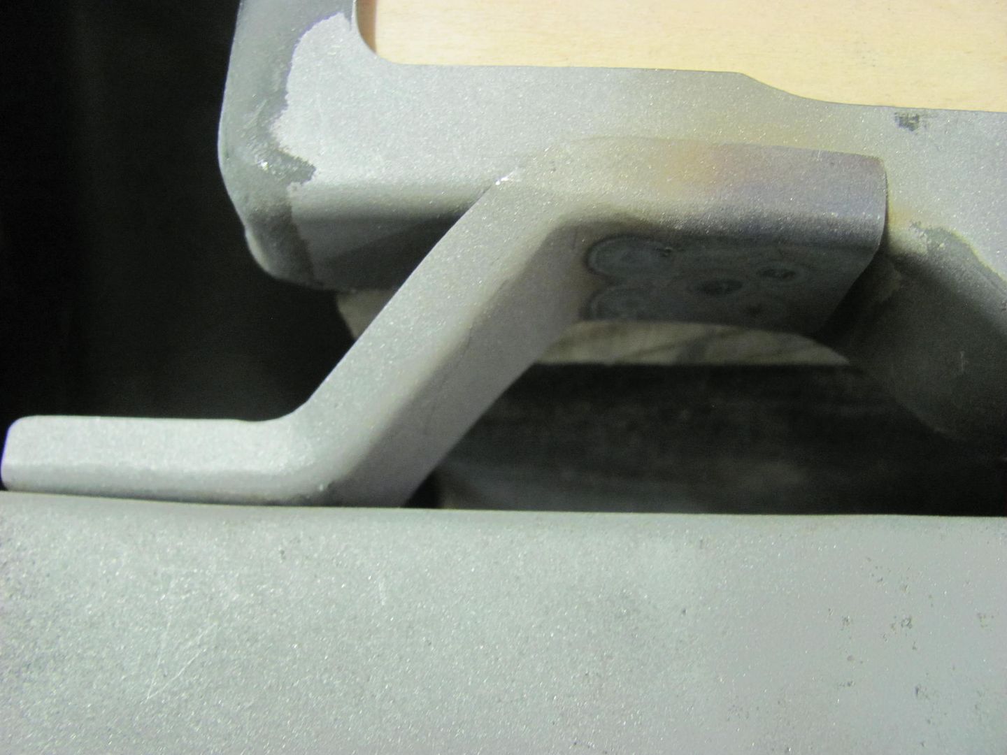
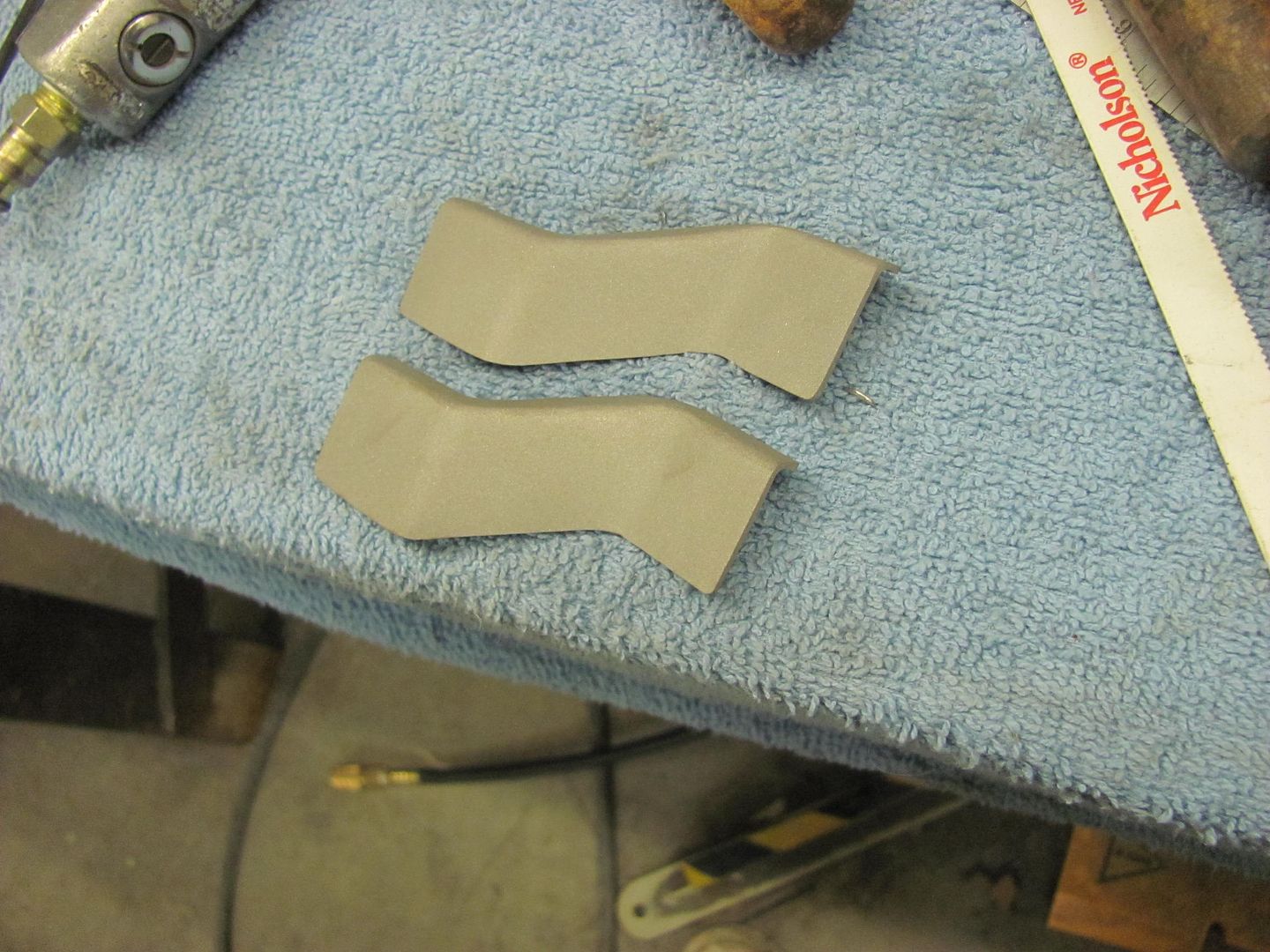
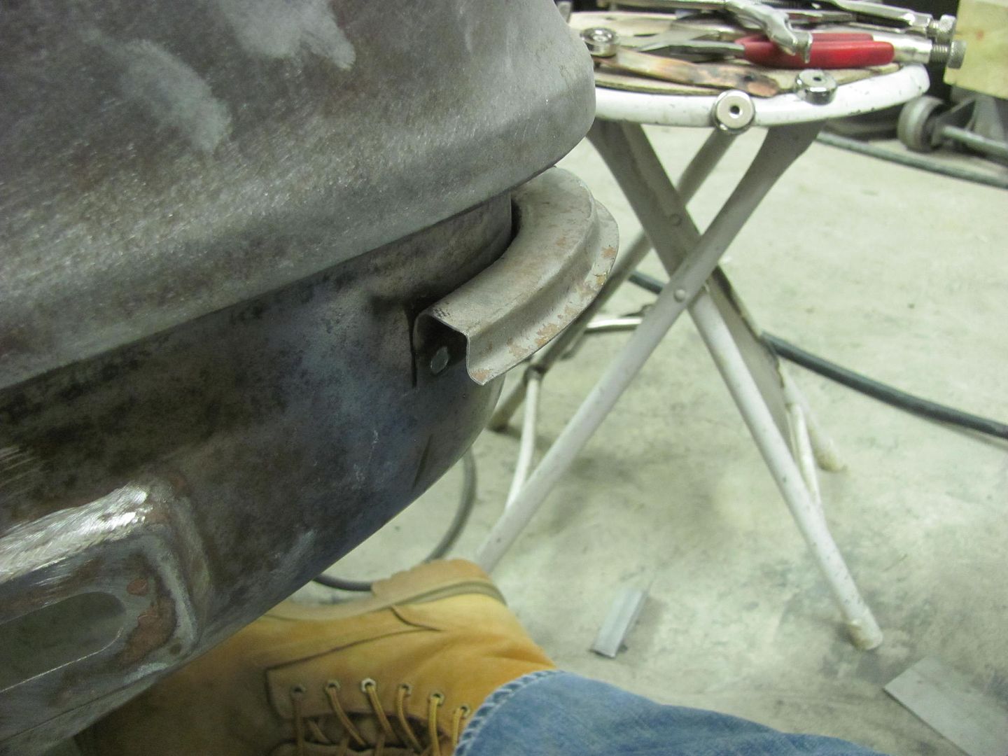
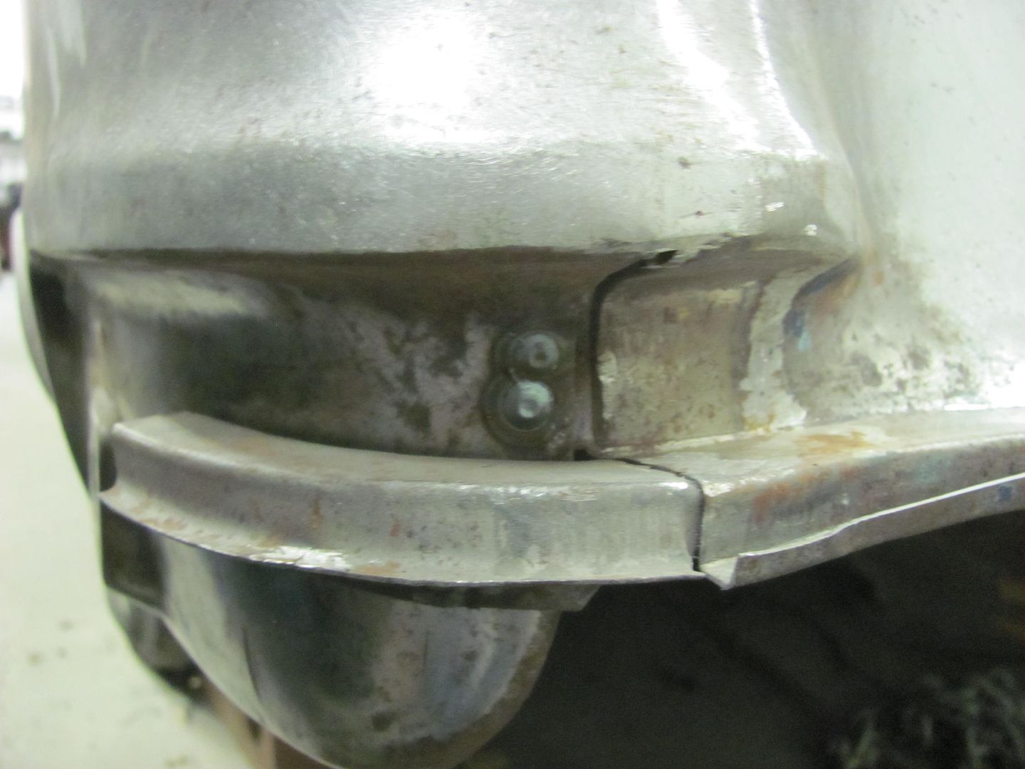
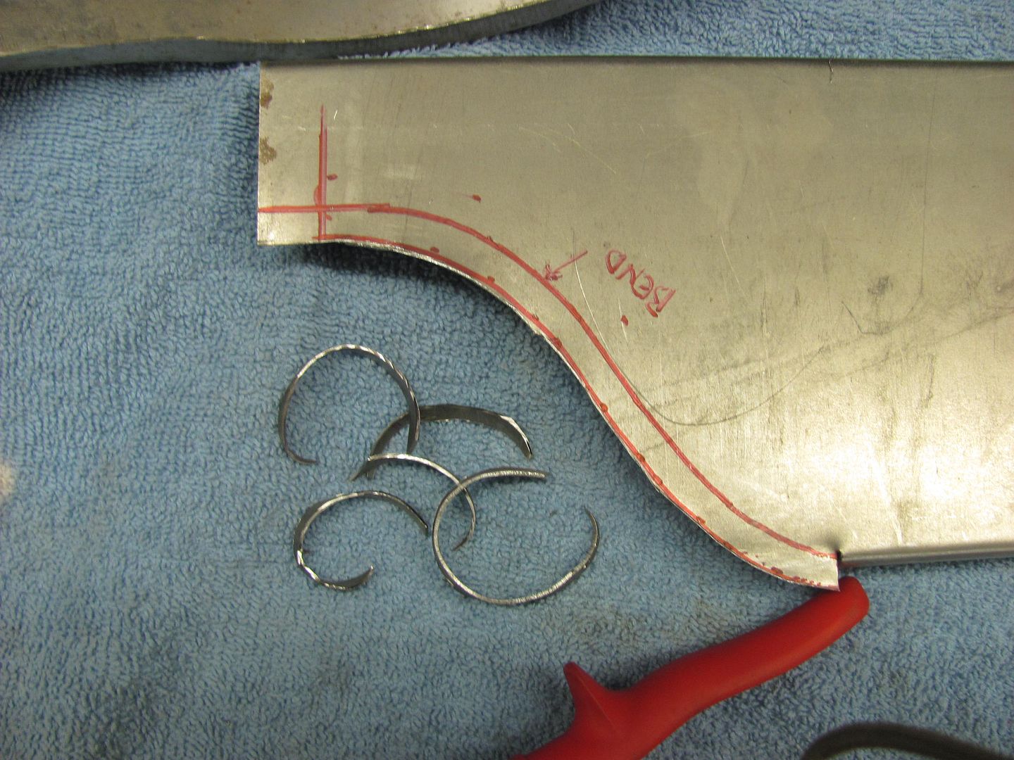
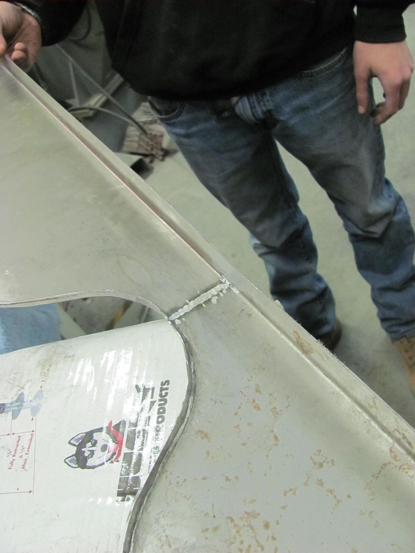
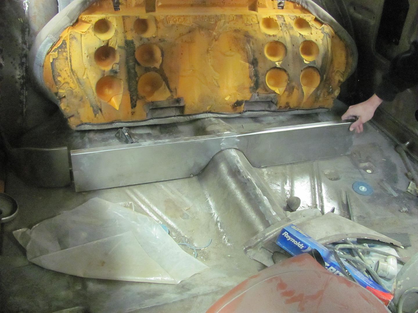
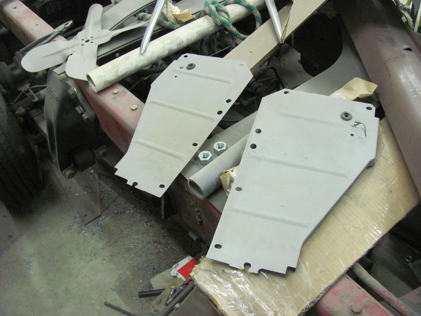
A while back we had made the brackets to make up three "reproduction" battery trays based on a 1955 Chevy factory air conditioned car.
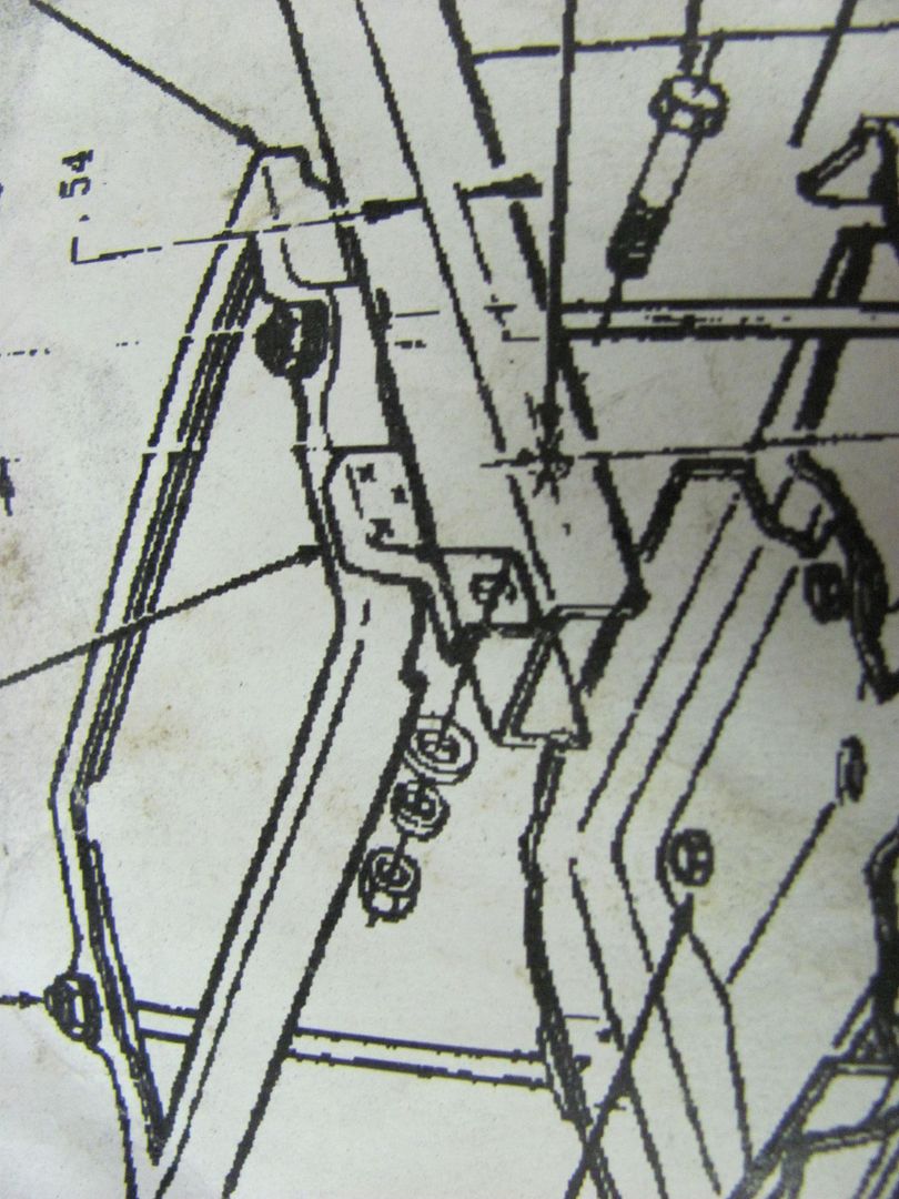
The only part that did not come with the used original pieces we had as patterns was the factory hold down with it's attached "zee" bracket that secures the battery hold down to the rear of the core support, as seen here in the factory assembly bulletin.
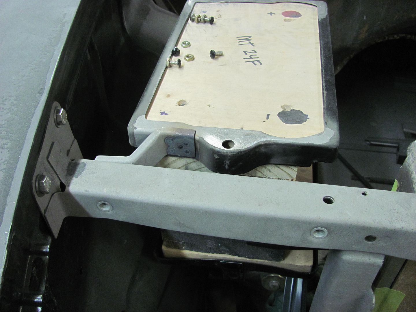
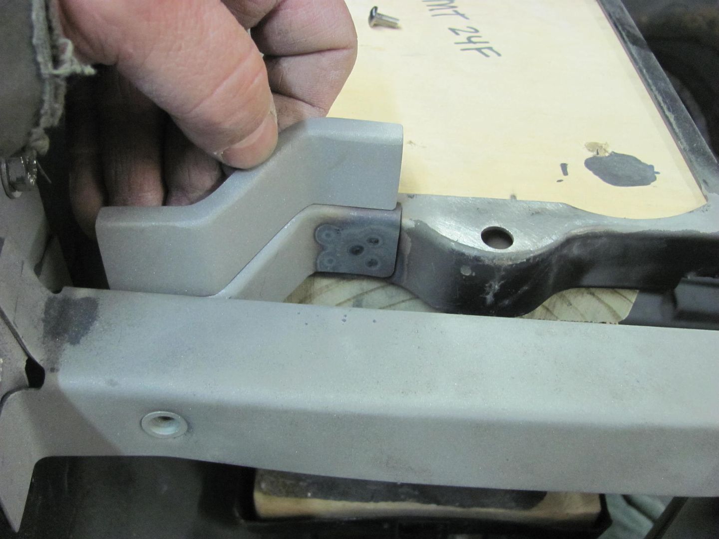
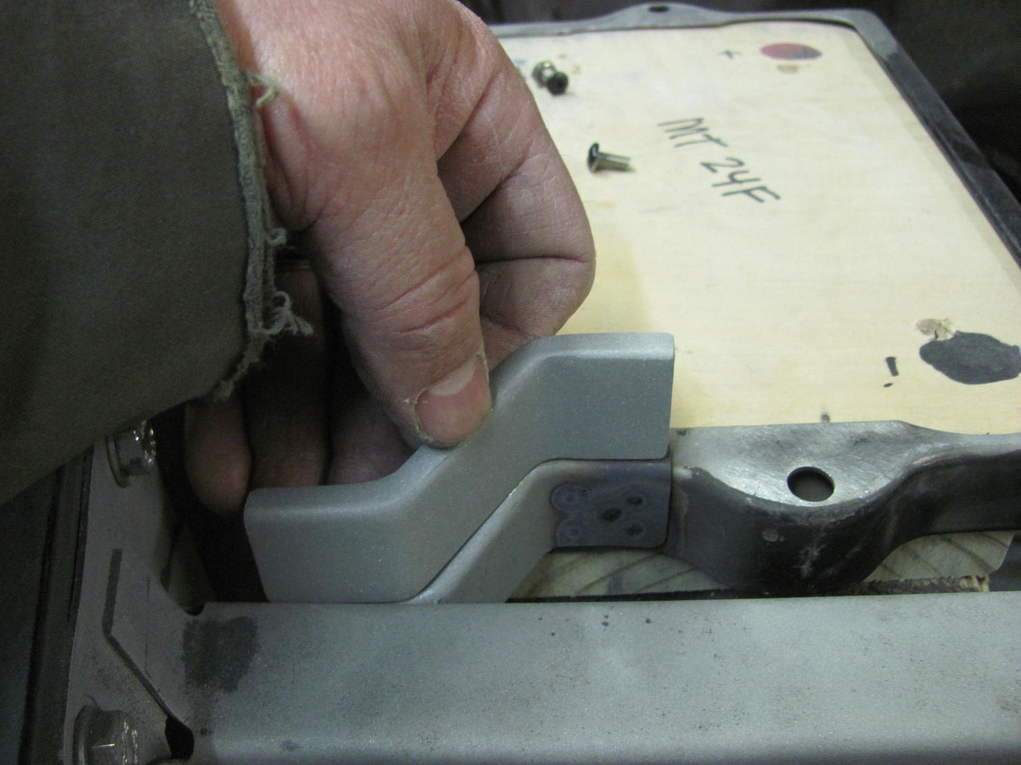
We recently mocked up the battery location, and made a zee bracket based on the picture and the dimensions we had in front of us.
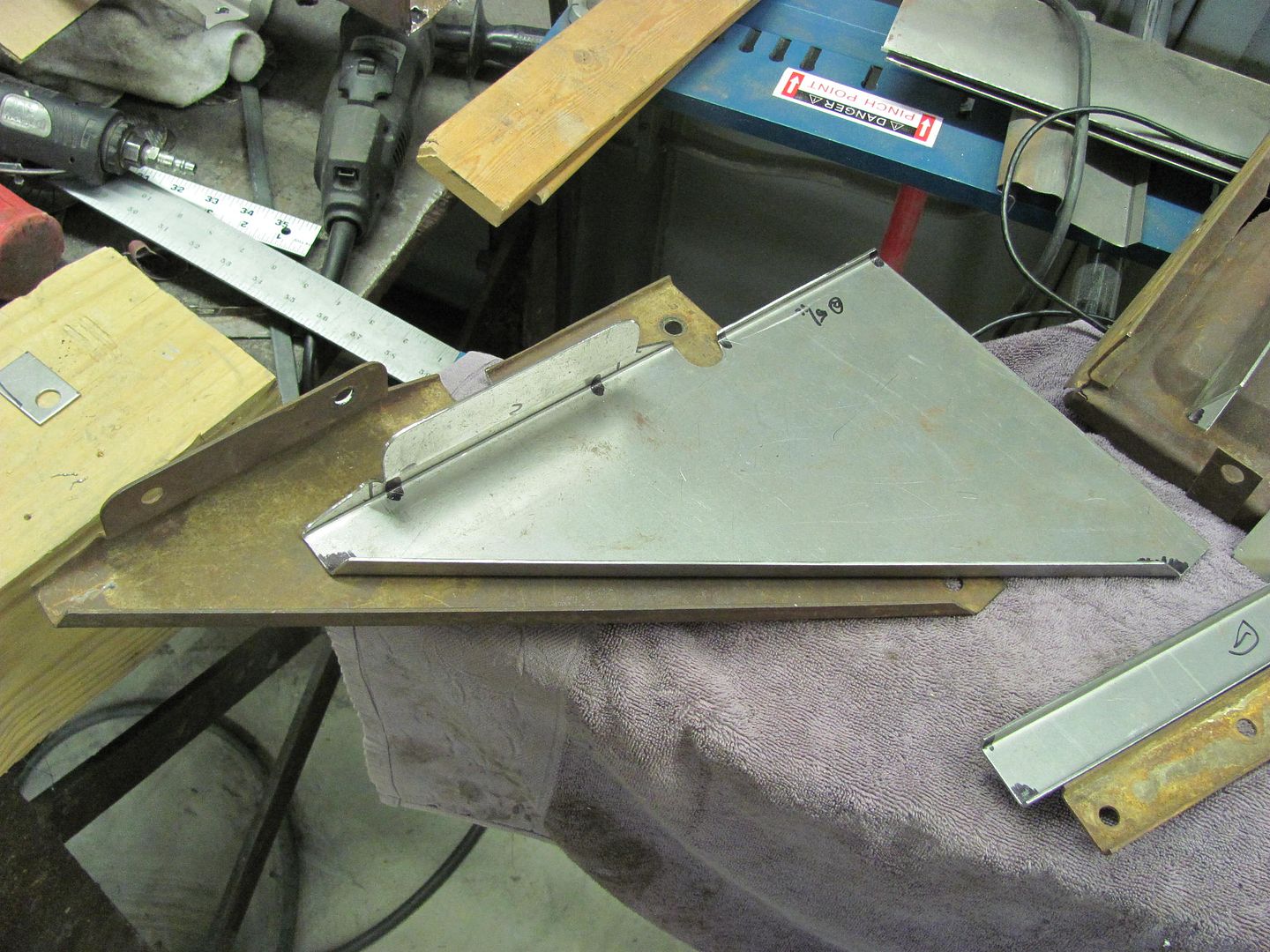
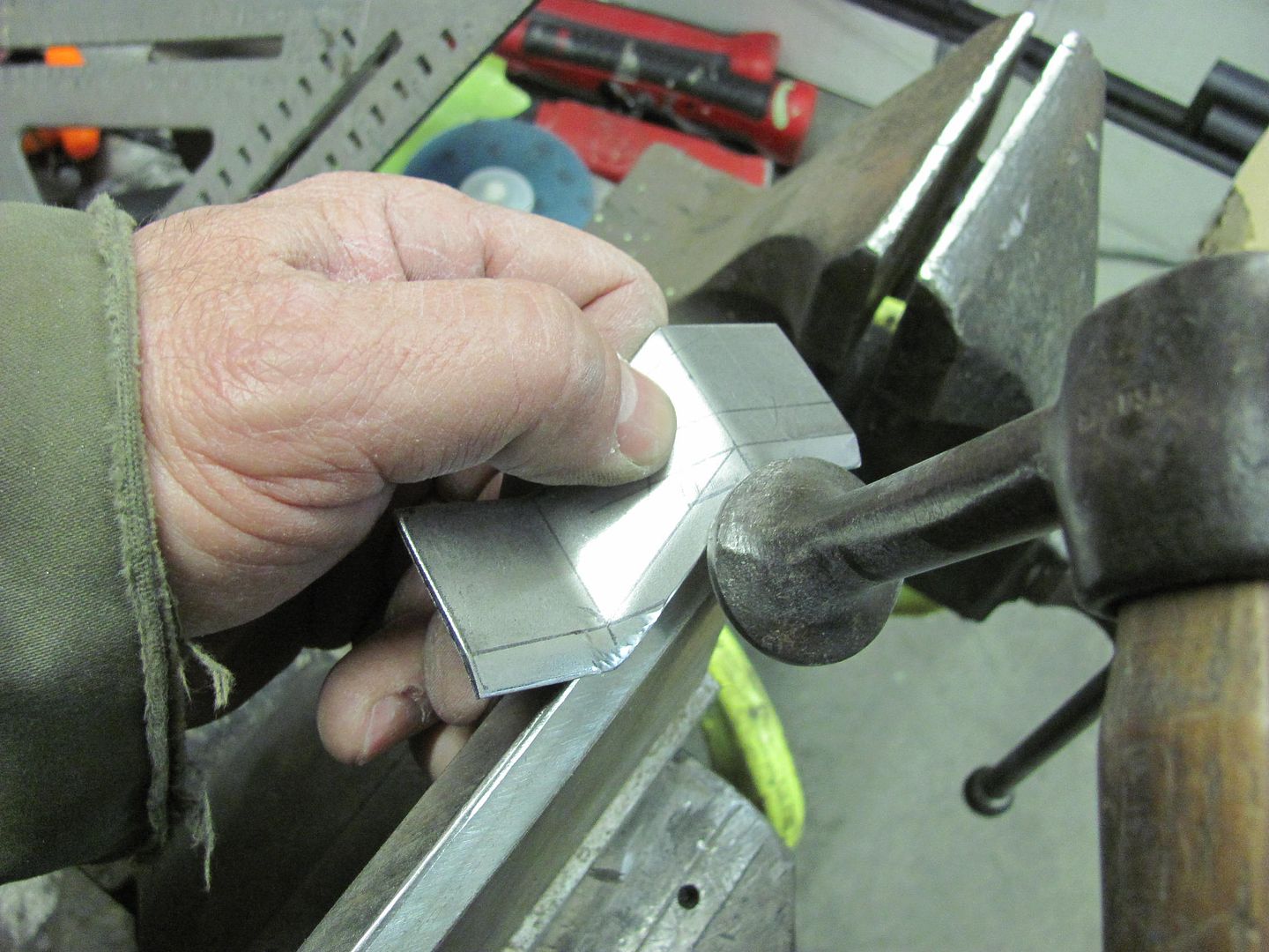
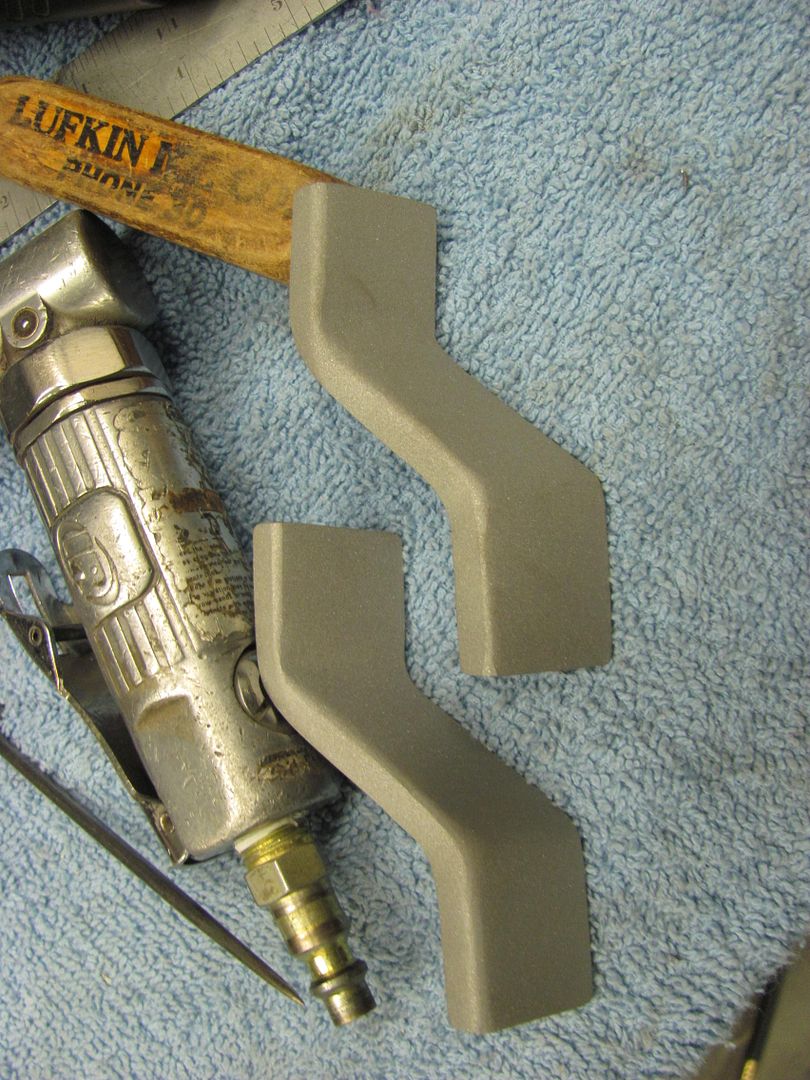
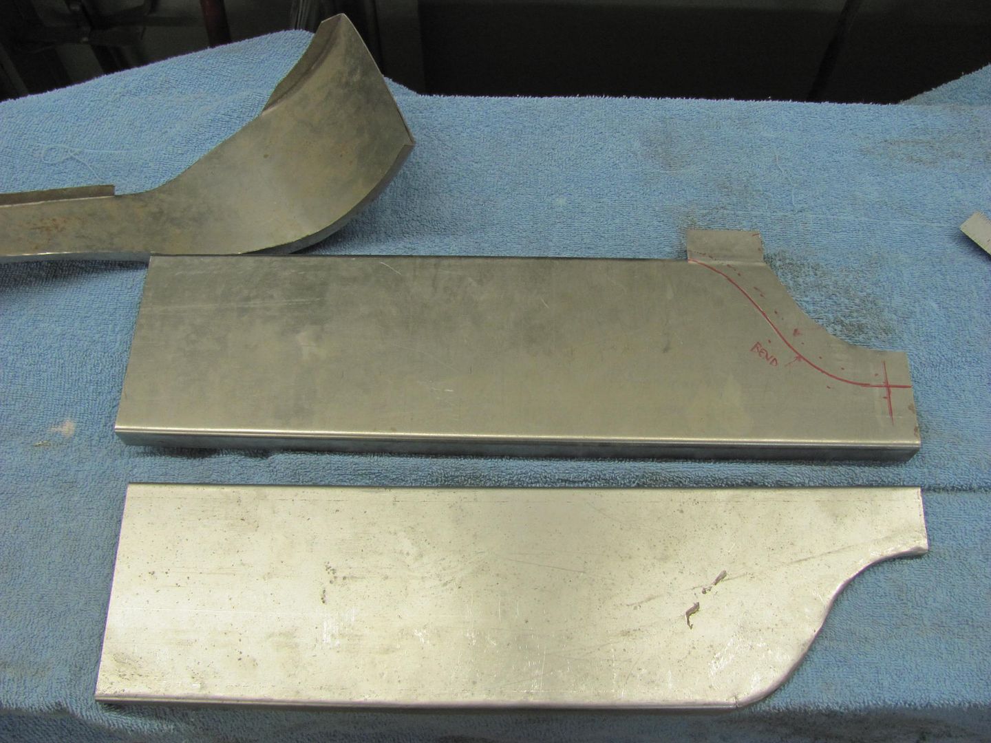
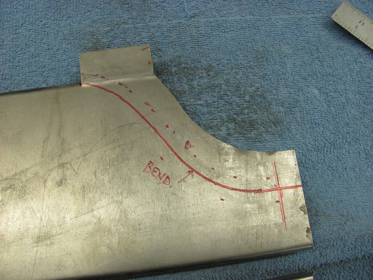
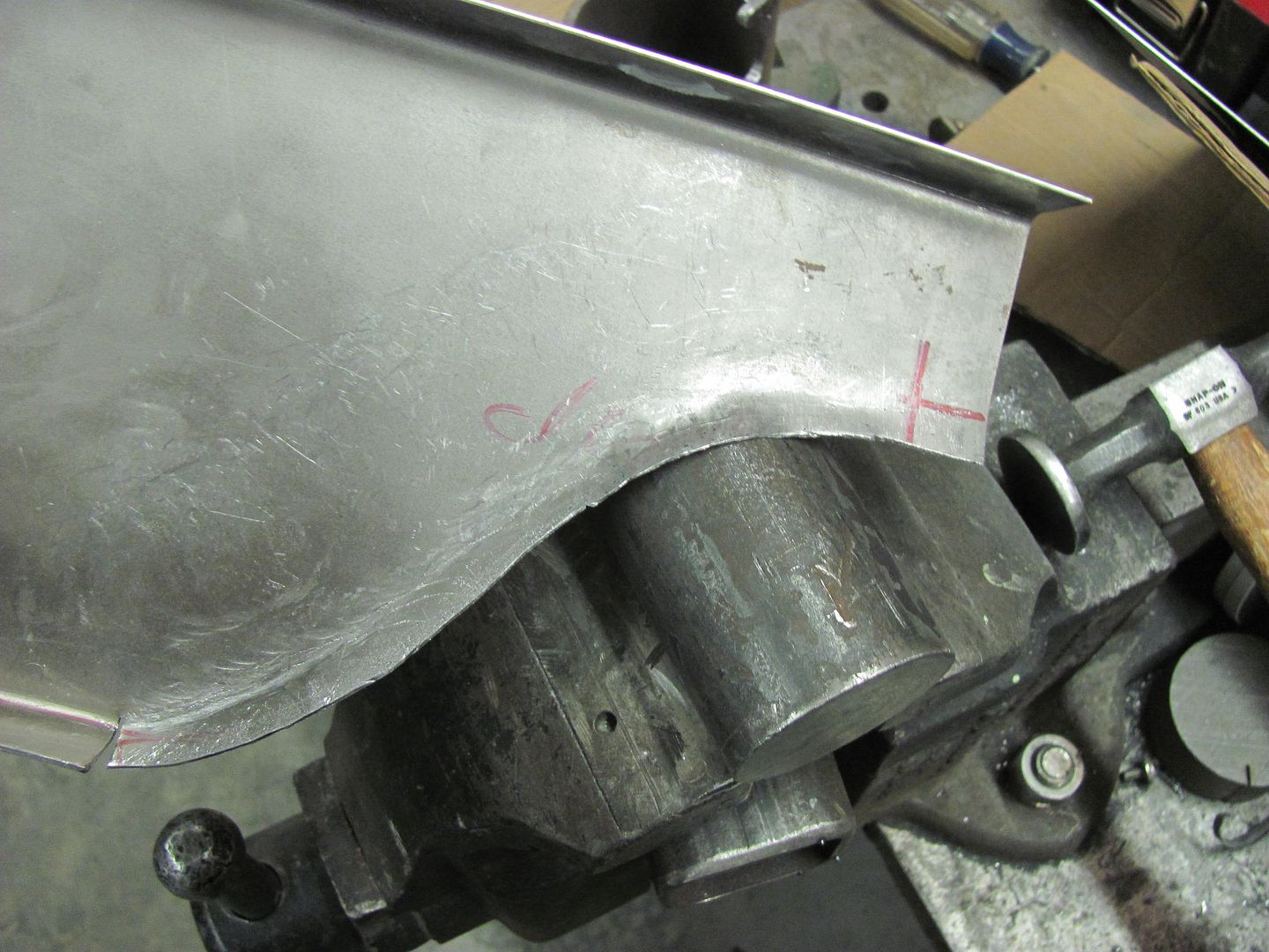
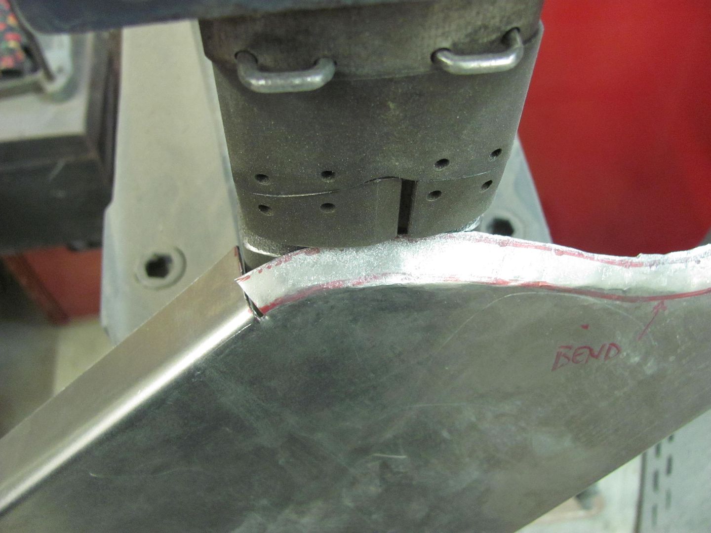
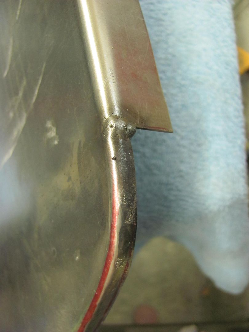
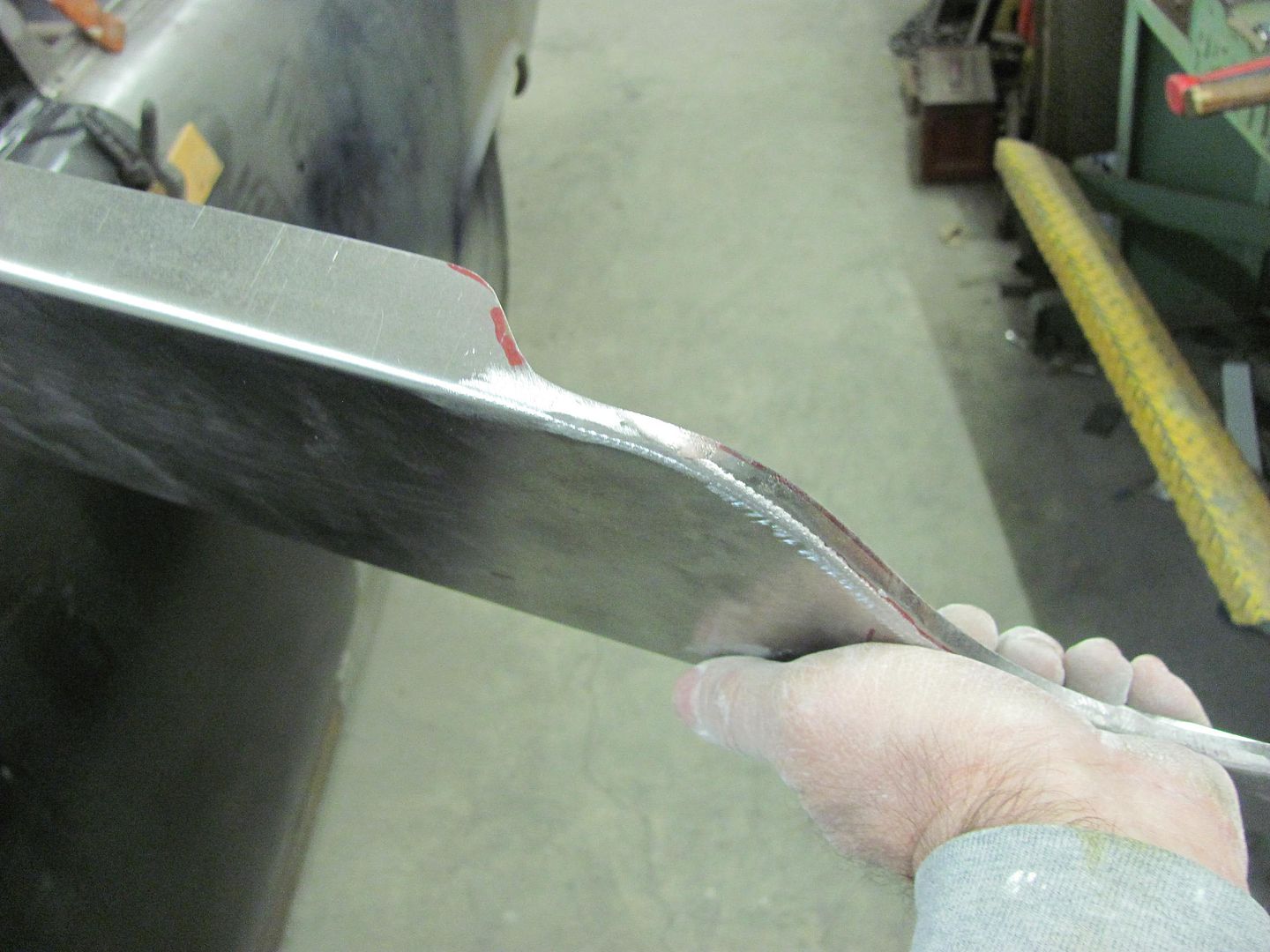
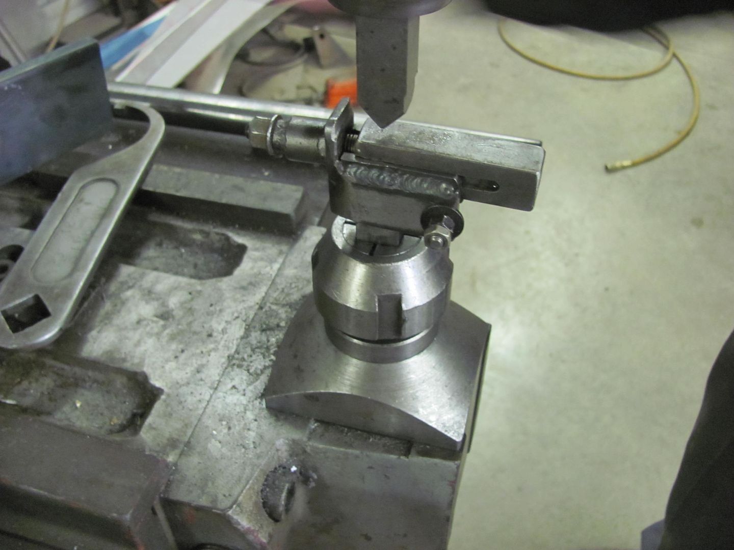
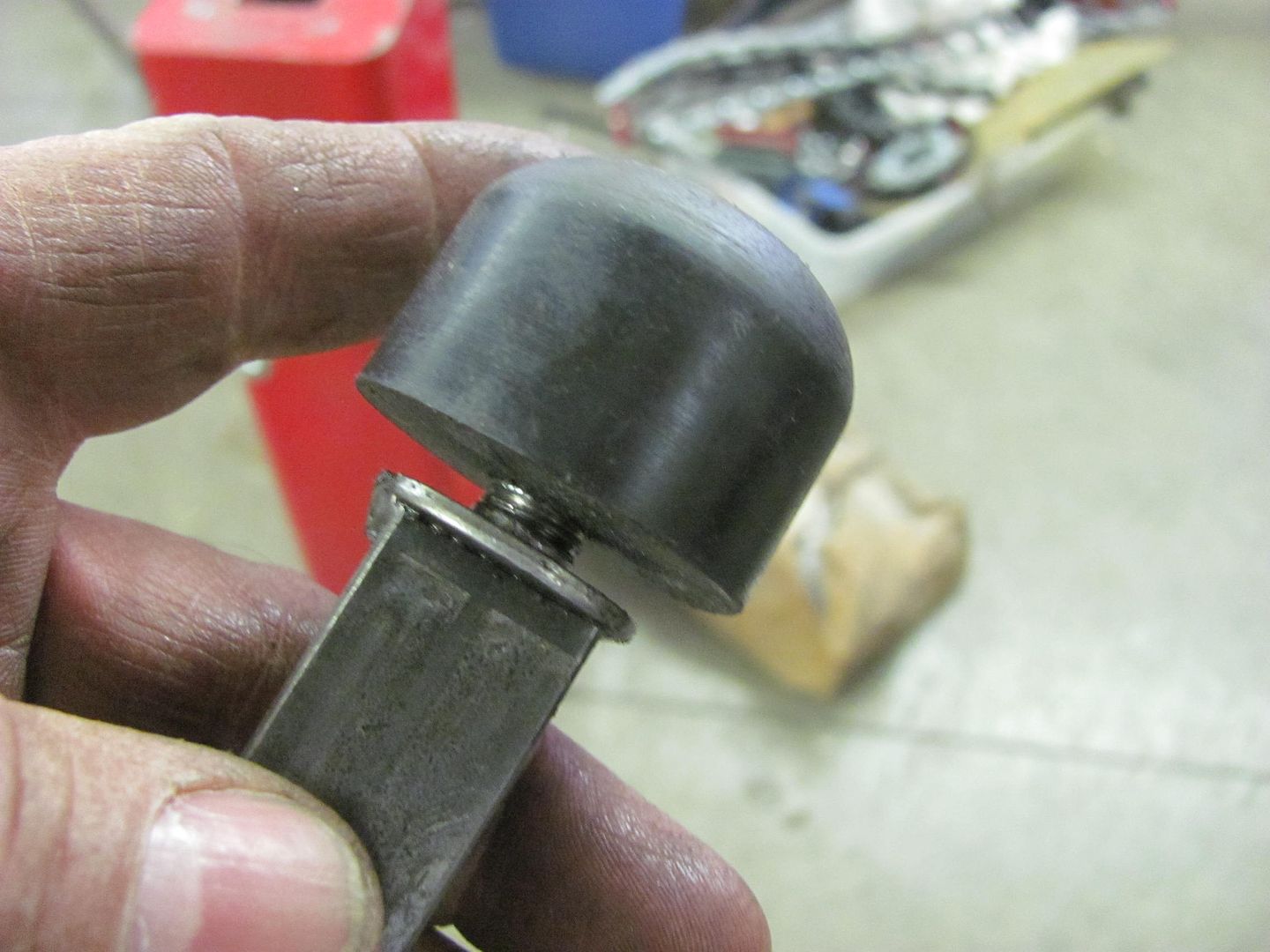
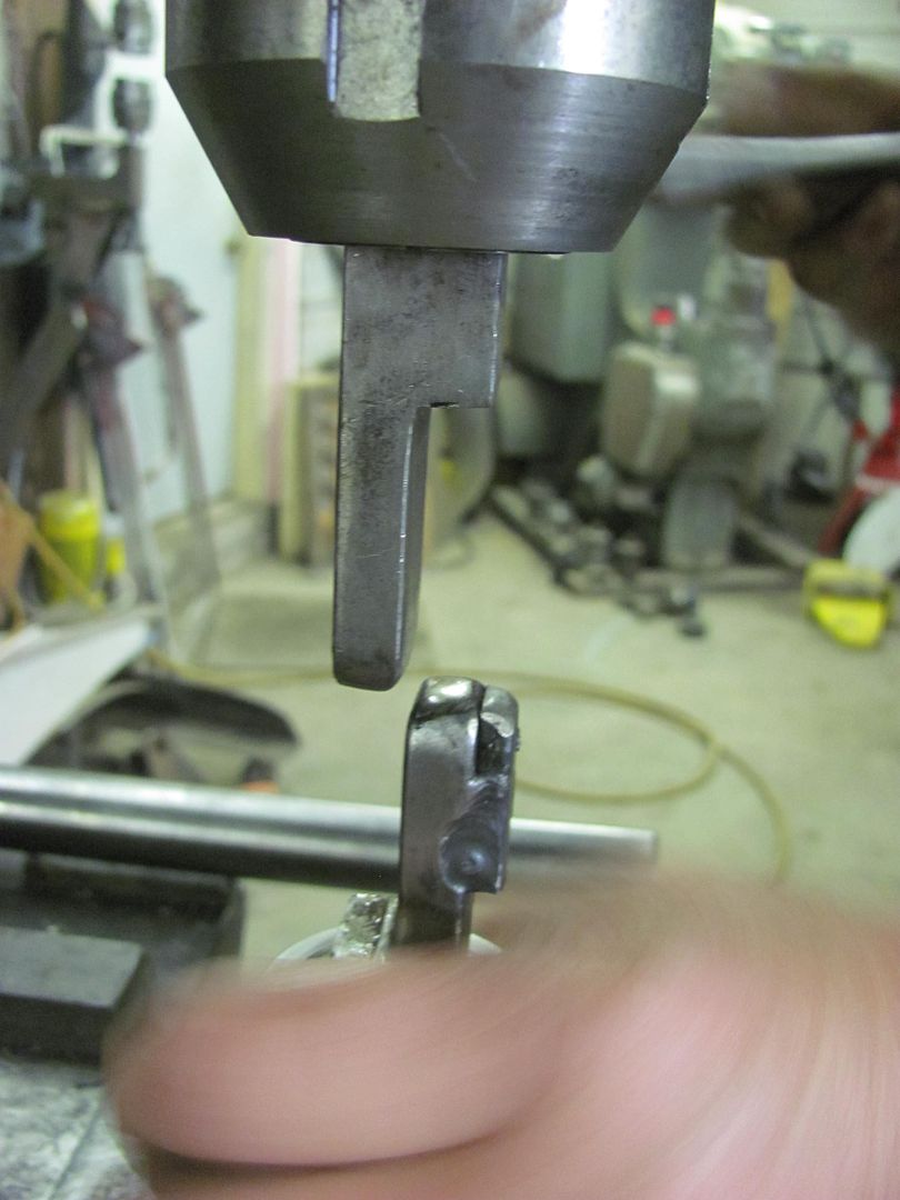
Now to make the remaining two brackets for the other two battery trays.. A roll former die in the press brake was used to make the vertical bends.
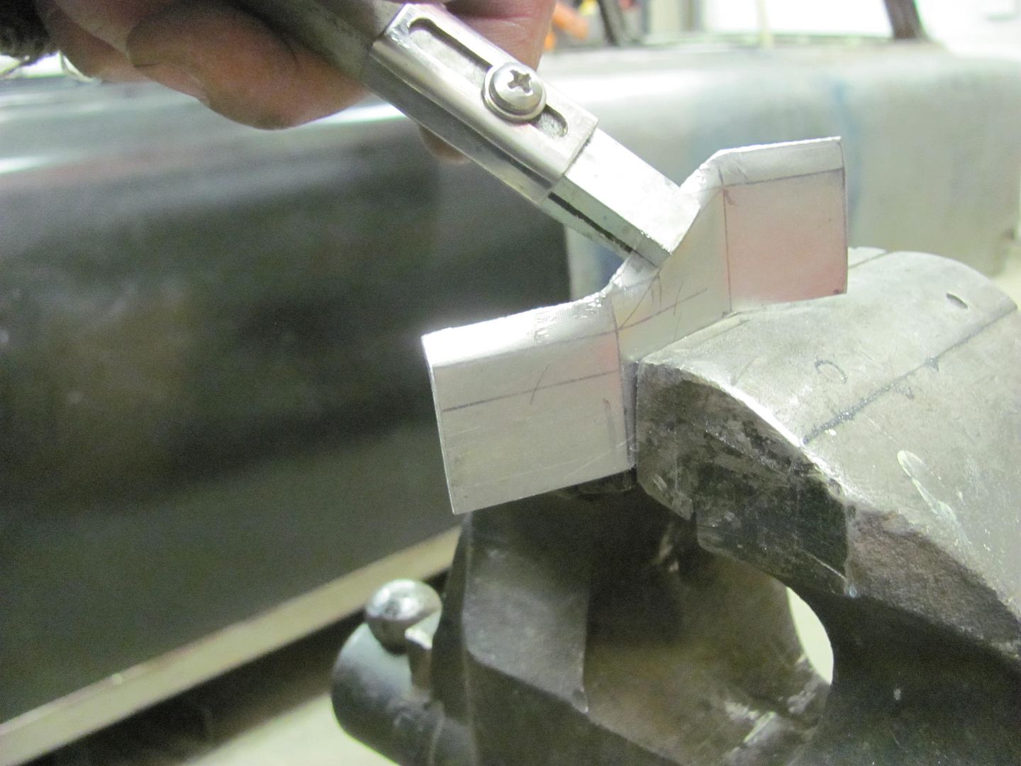
A bit of tipping using a press brake die as an anvil, and then using the tipping tool...
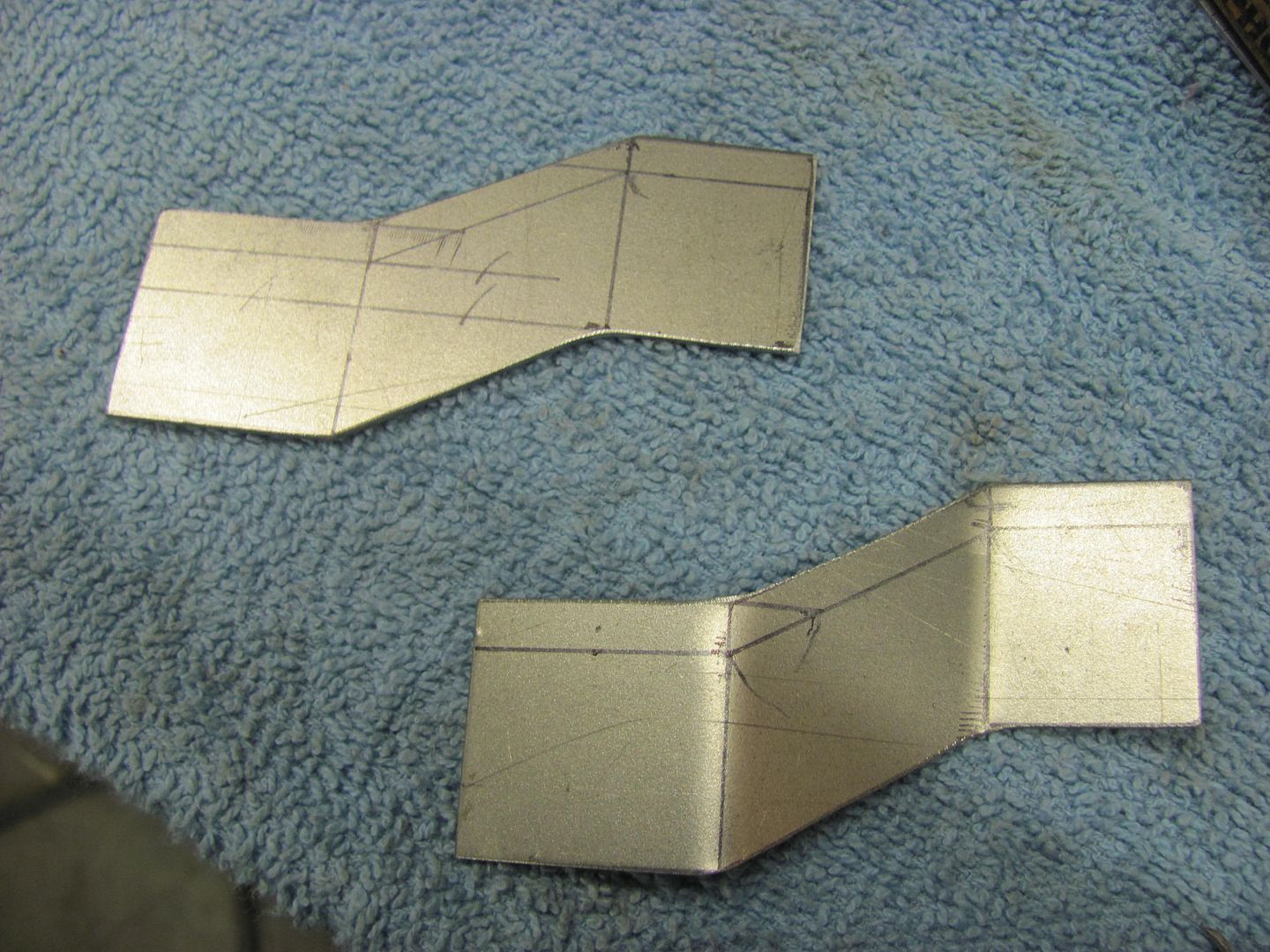
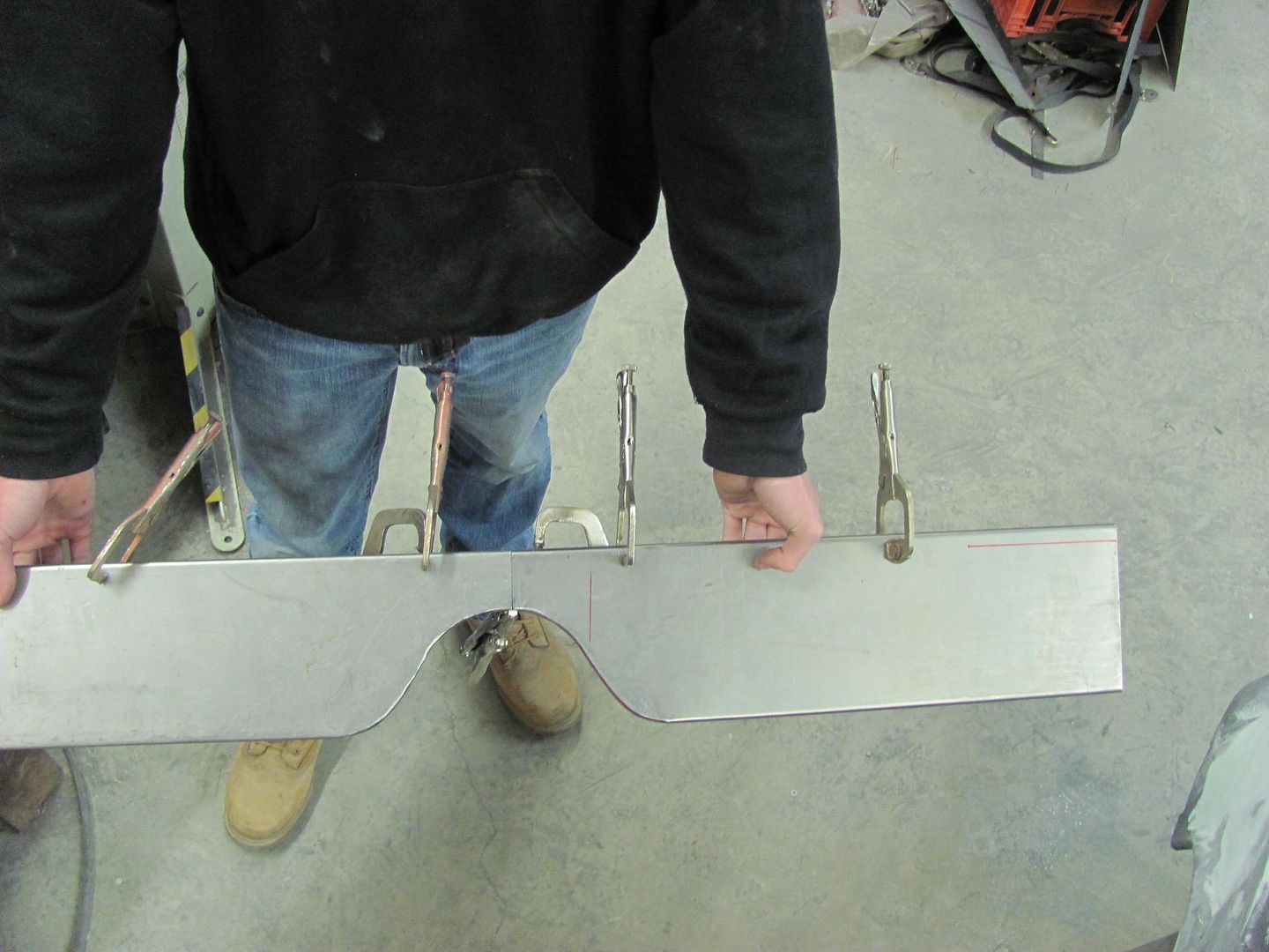
The finished brackets and a comparison....
The only part that did not come with the used original pieces we had as patterns was the factory hold down with it's attached "zee" bracket that secures the battery hold down to the rear of the core support, as seen here in the factory assembly bulletin.
We recently mocked up the battery location, and made a zee bracket based on the picture and the dimensions we had in front of us.
Now to make the remaining two brackets for the other two battery trays.. A roll former die in the press brake was used to make the vertical bends.
A bit of tipping using a press brake die as an anvil, and then using the tipping tool...
The finished brackets and a comparison....
MP&C
Member
Kyle finishing up the hood brace..
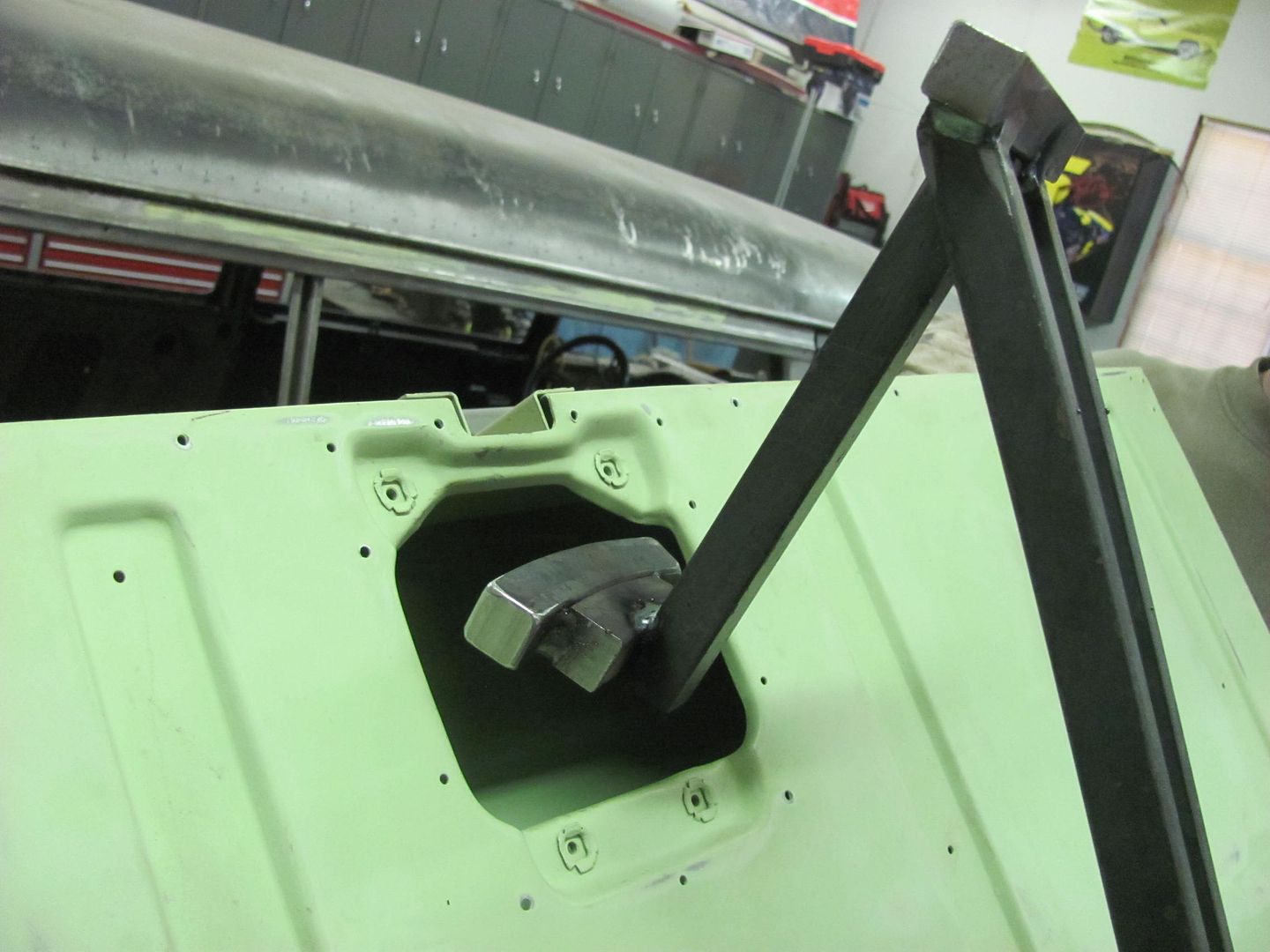
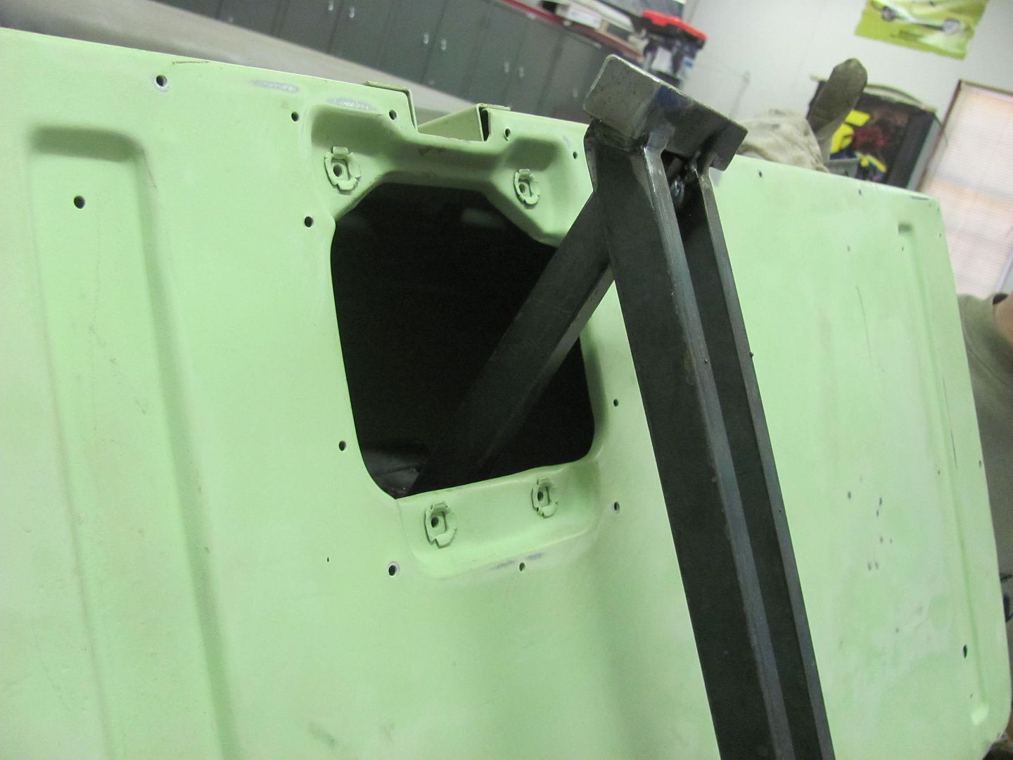
Well as I still hadn't finished blocking the front end, rather than pull the core support just yet, Kyle will start on the rear of the wagon in wrapping up some details there. Before pulling the tailgate, there was one gap that was inconsistent, so I gave him a hand with the rework before he got welding..
First to unfold the flange a bit...
Next, some 14 gauge steel was cut out and a strengthening bend added to use for some friendly persuasion..
Refolded...
For comparison, before:
After:
Then we tweaked the twist of the tailgate for good fitment to the opening and Kyle added three plug welds down each side to lock the skin to the inner tail gate.
...Then we removed the tail gate so he could finish the plug welds for the top flange of the tail pan, I had only tacked it in place when the tailpan was installed, so this should help check off another item from the list......
Meanwhile I continued blocking out the front end..
MP&C
Member
Well Kyle skipped out on me tonight, something about a birthday and his parents taking him out to dinner.. and here he could have been welding!
So I took the opportunity to have dinner with the family, so tonight was a short night...
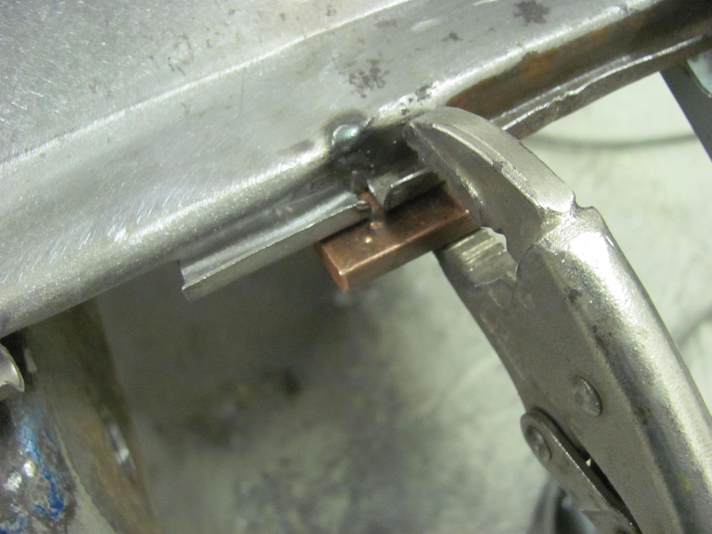
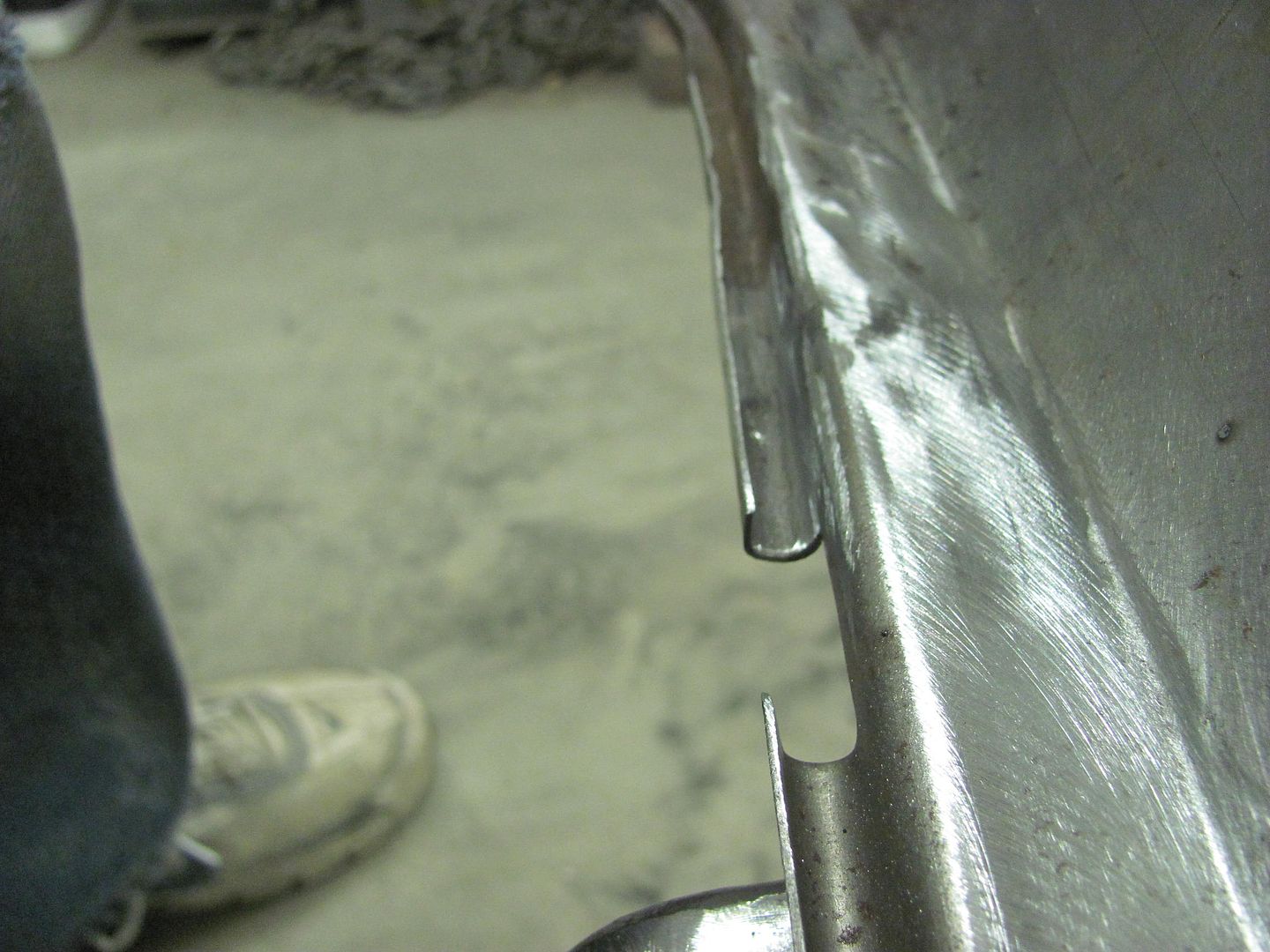
One of the other areas I skipped over at the rear of the wagon was when the tail pan was installed. The factory version with the pinch welded flanges has a gap in the crimp seam for the rear bumper seal:
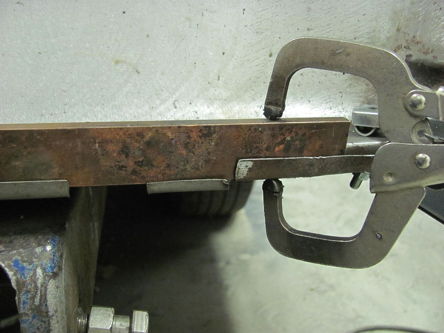
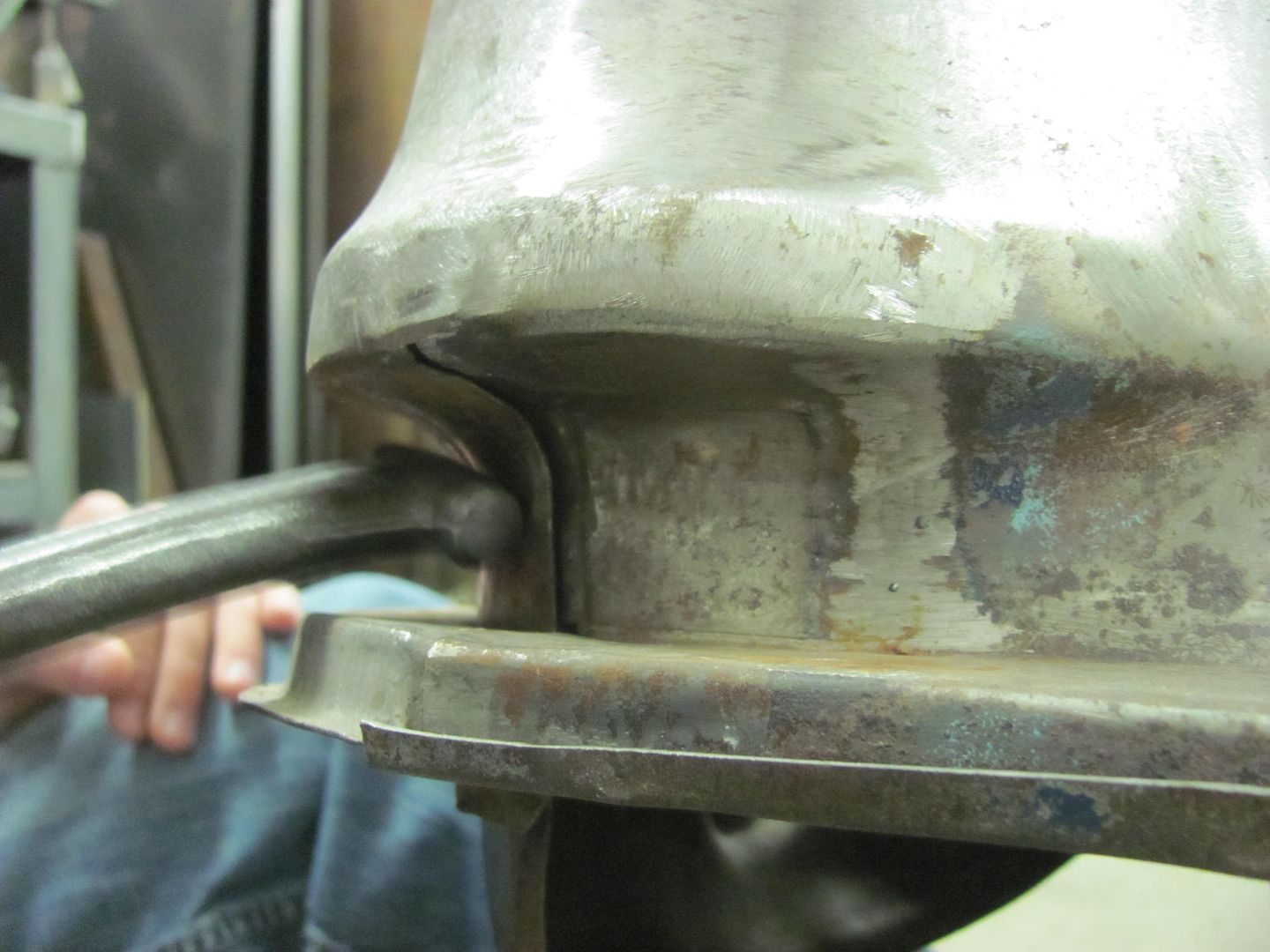
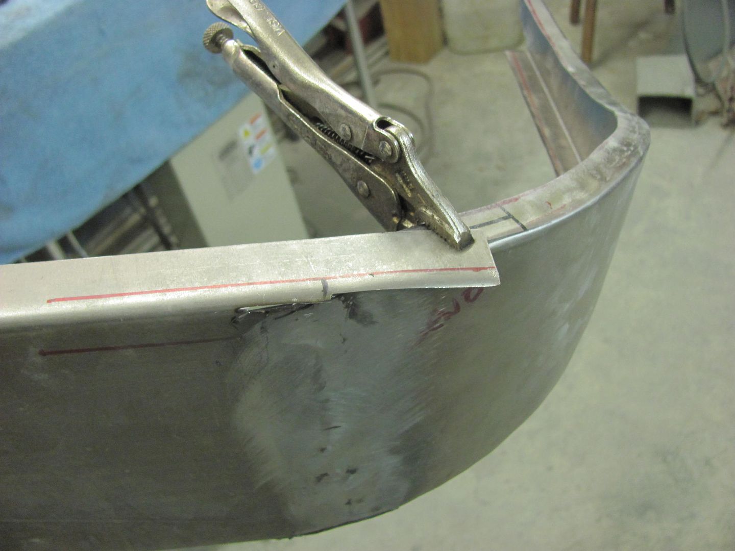
As I got rid of all the pinch weld seams at the rear of the wagon to eliminate those rust traps, the gap at the crimp seam will be filled in. To assist in filling in the wide gap, a piece of copper flat bar is used as a backer..
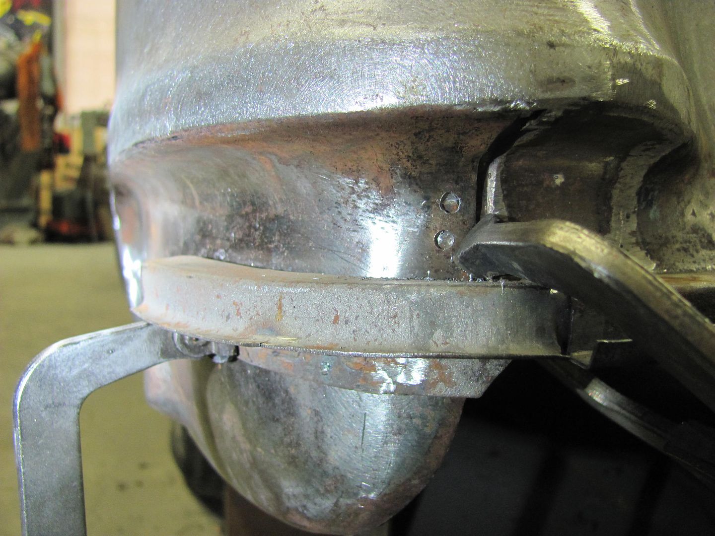
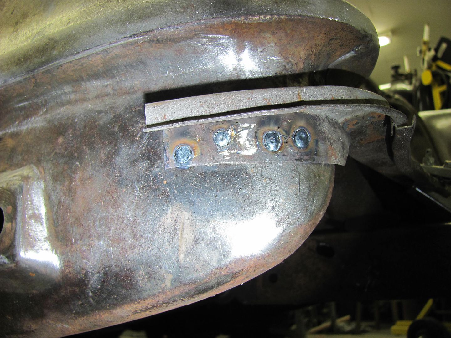
Next, as the reproduction tail pan has a rounded crimp seam and the area on the original quarters is more of a square, we'll add some hammer action here. The remaining piece of the flat bar is clamped in and used as an anvil..
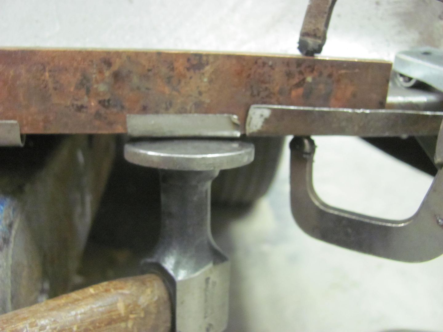
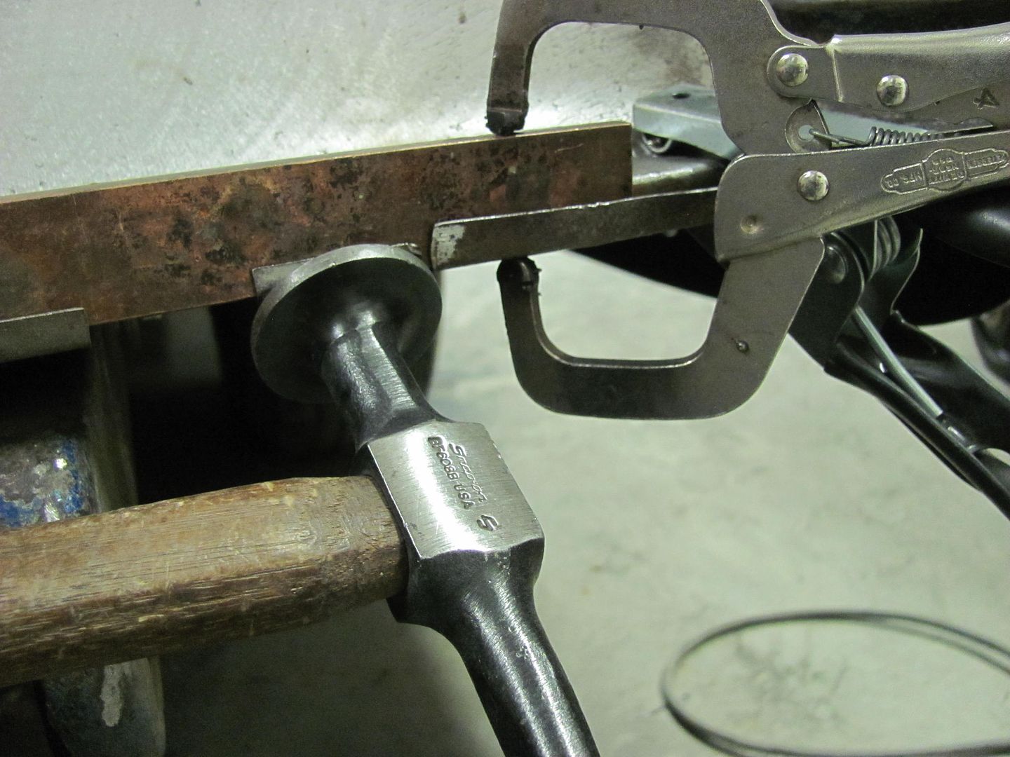
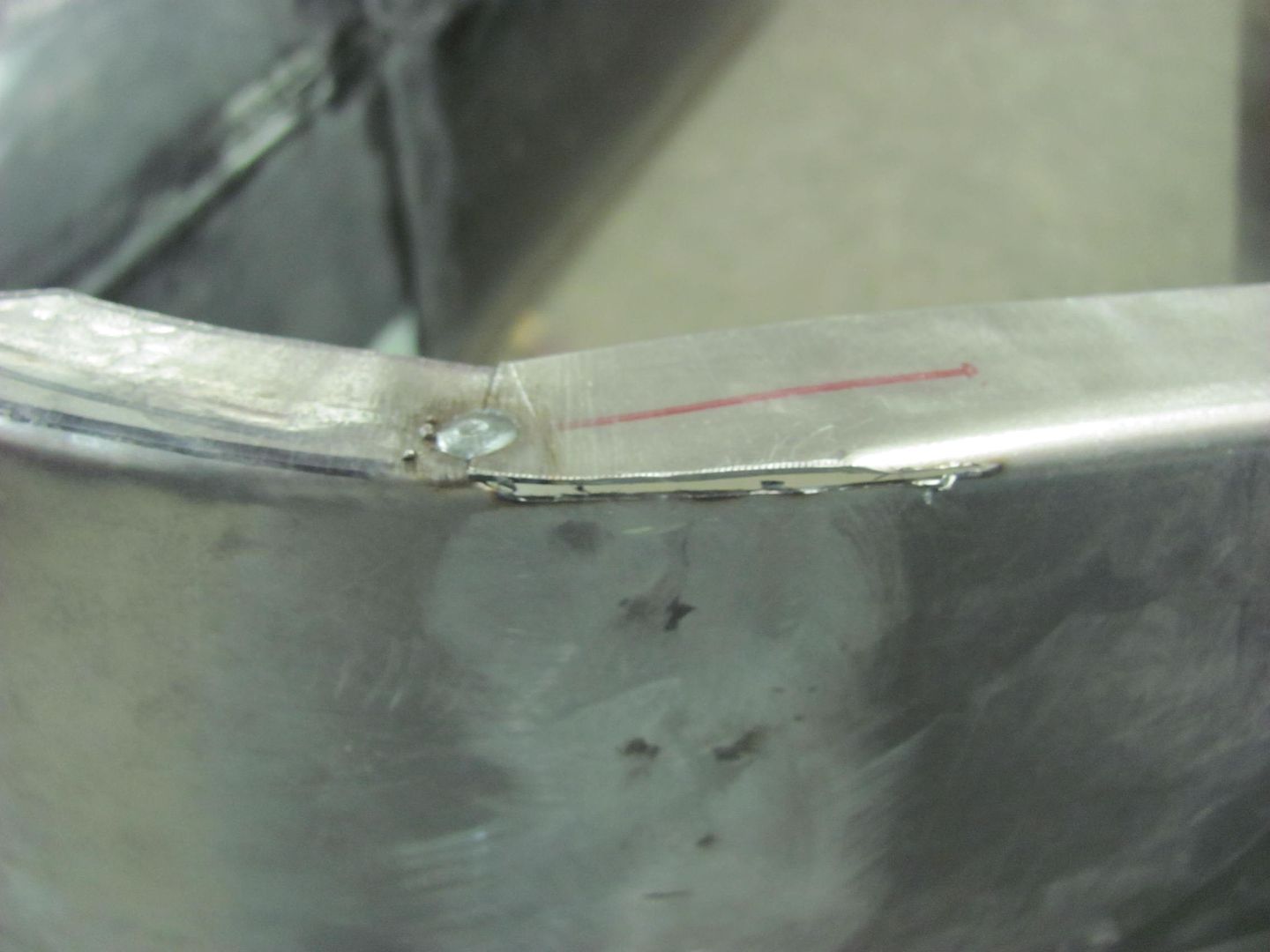
Continuing welding...
.....and a repeat on the driver's side...
So I took the opportunity to have dinner with the family, so tonight was a short night...
One of the other areas I skipped over at the rear of the wagon was when the tail pan was installed. The factory version with the pinch welded flanges has a gap in the crimp seam for the rear bumper seal:
As I got rid of all the pinch weld seams at the rear of the wagon to eliminate those rust traps, the gap at the crimp seam will be filled in. To assist in filling in the wide gap, a piece of copper flat bar is used as a backer..
Next, as the reproduction tail pan has a rounded crimp seam and the area on the original quarters is more of a square, we'll add some hammer action here. The remaining piece of the flat bar is clamped in and used as an anvil..
Continuing welding...
.....and a repeat on the driver's side...
MP&C
Member
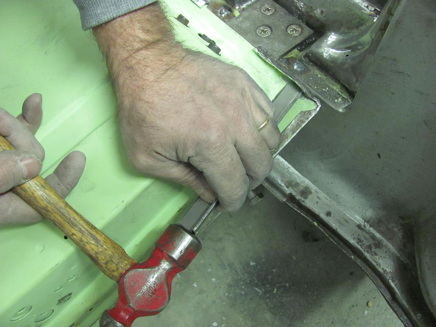
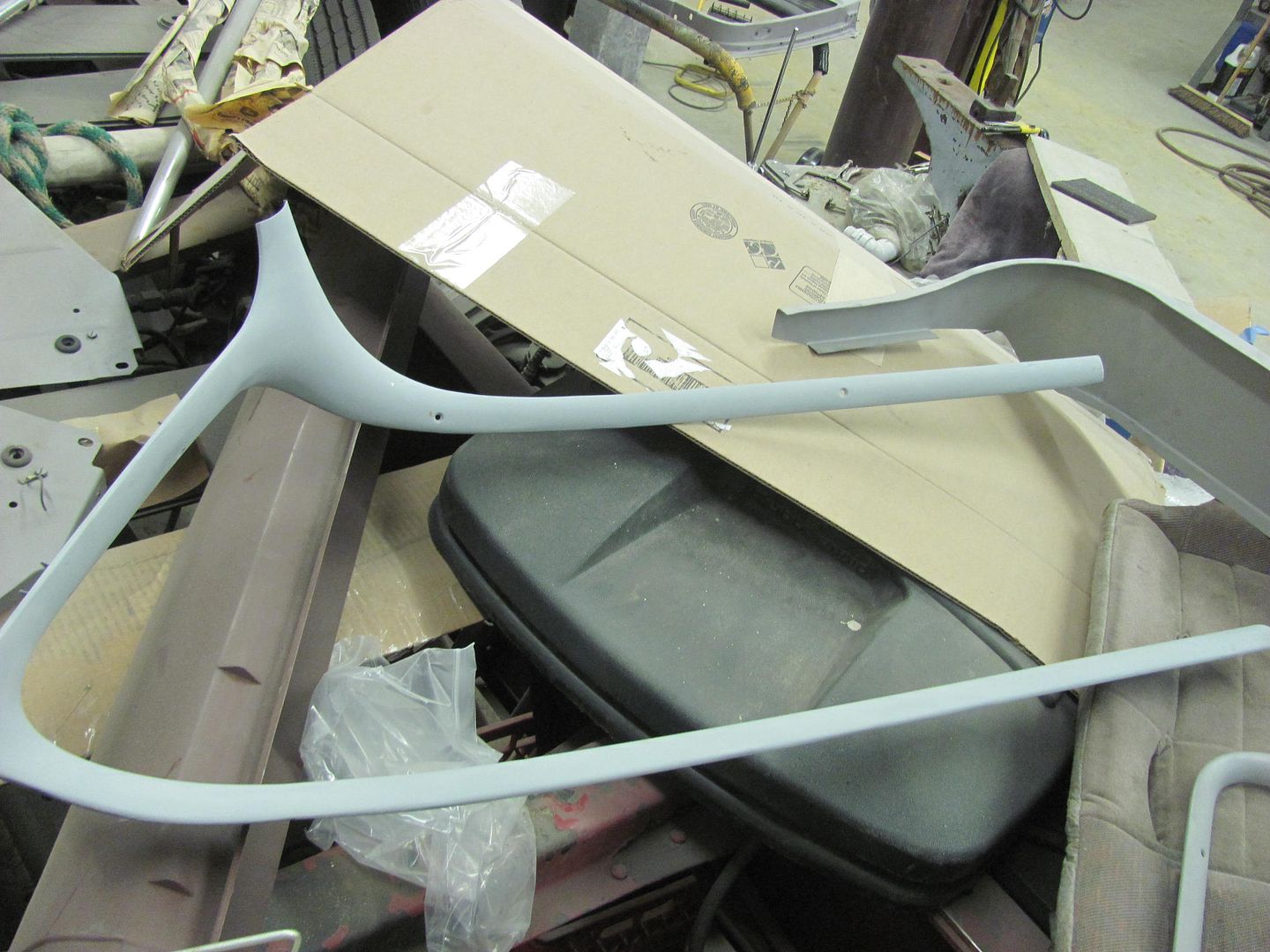
Finishing up another loose end, tying in the bottom of the NOS quarter panel.. A bit of hammer bumping to get the panels aligned...
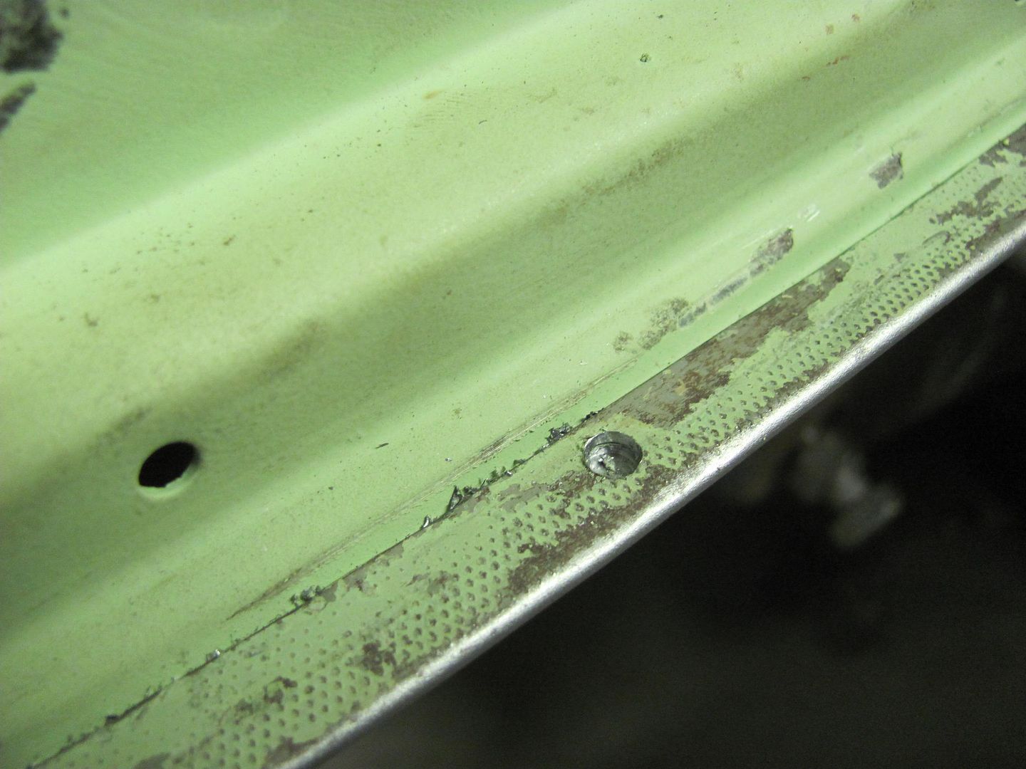
Plug weld holes drilled and filled.....
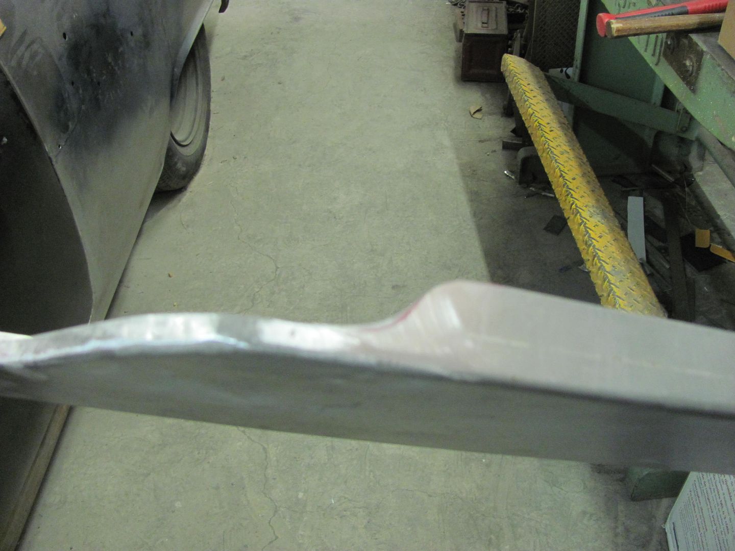
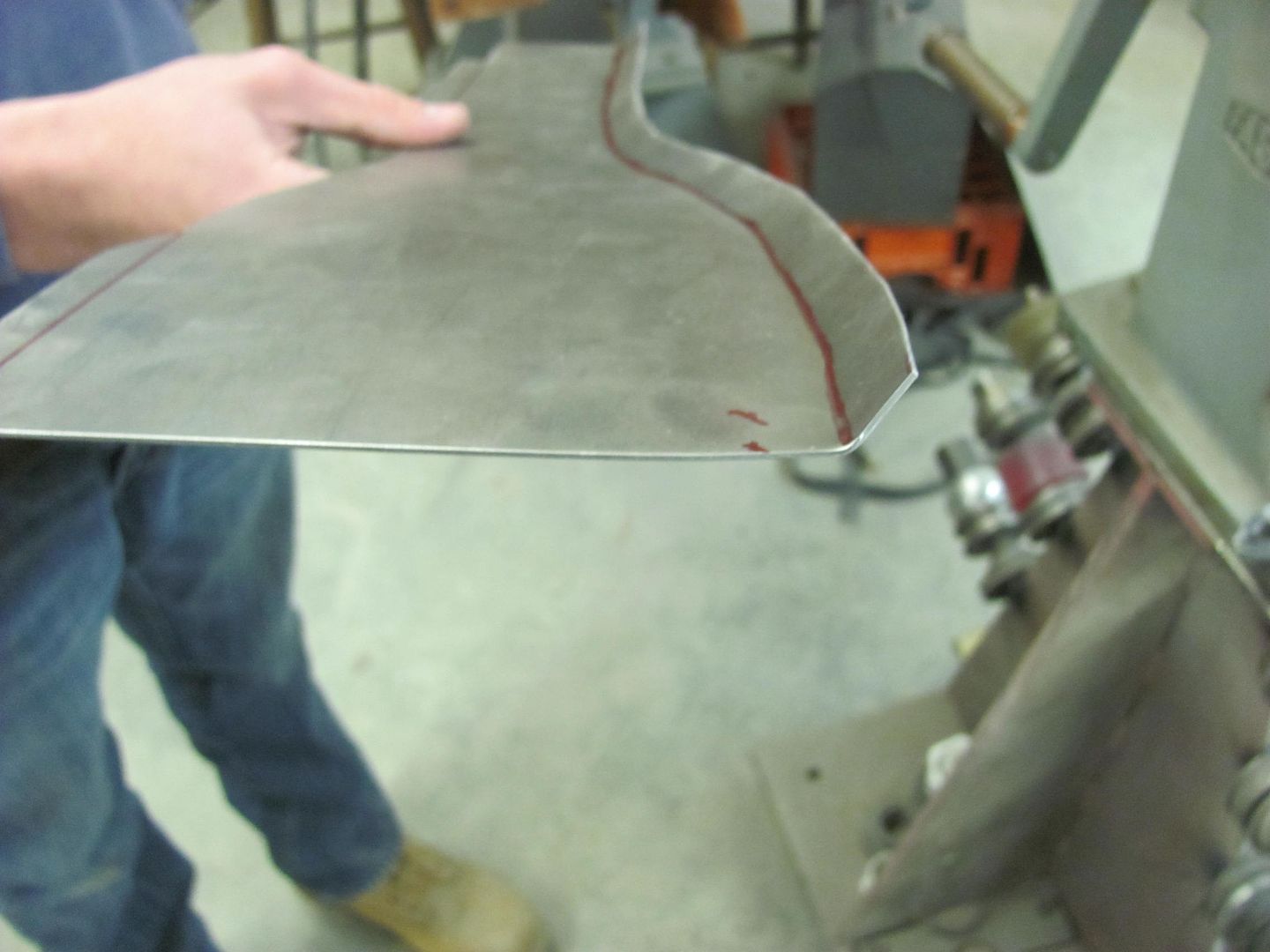
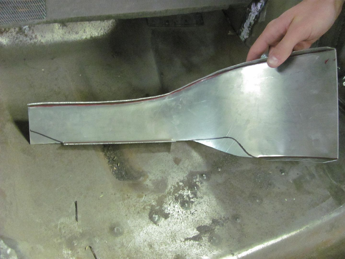
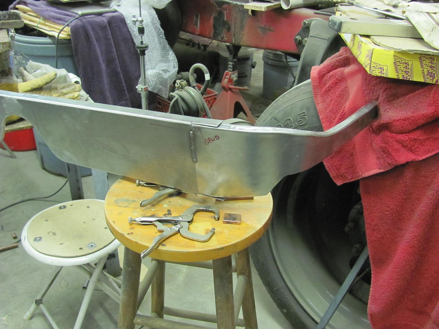
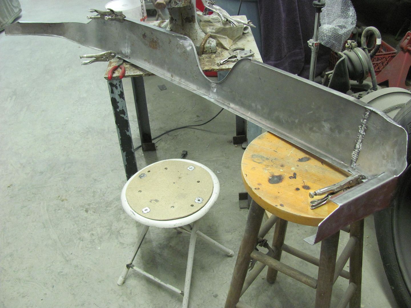
Then attention is turned to duplicating a second half for the front divider panel for the rear seat.
Using the Erco kick shrinker....
Here's the fitment of the two seat panels together, all clamped up for welding..
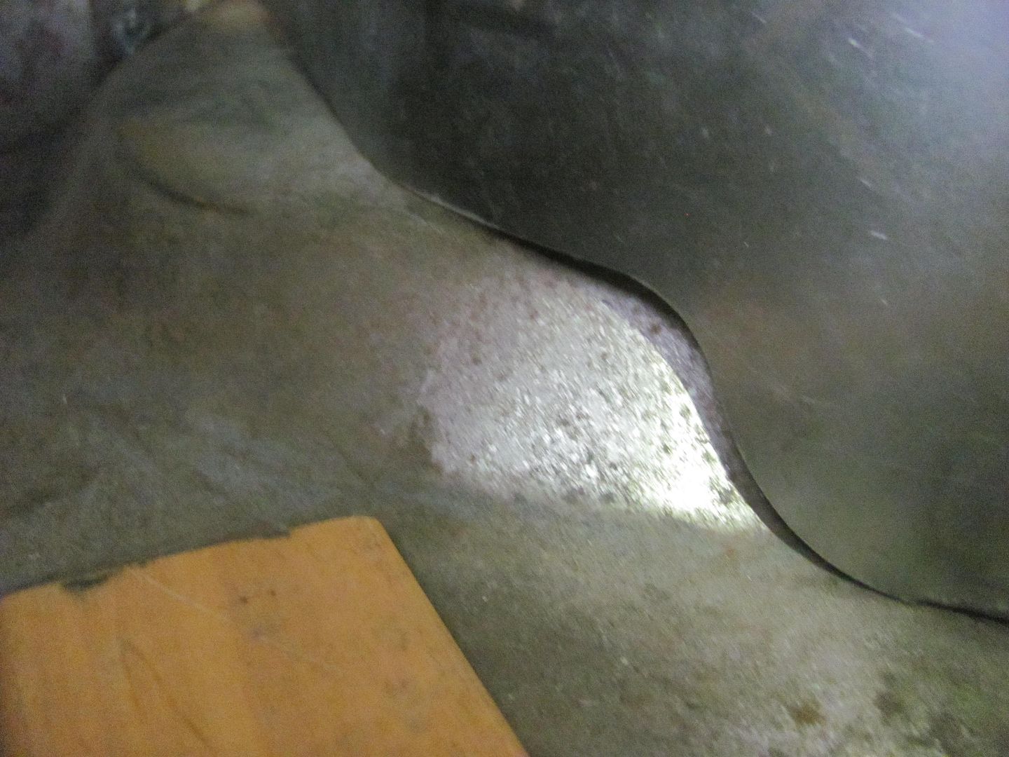
Test fit..
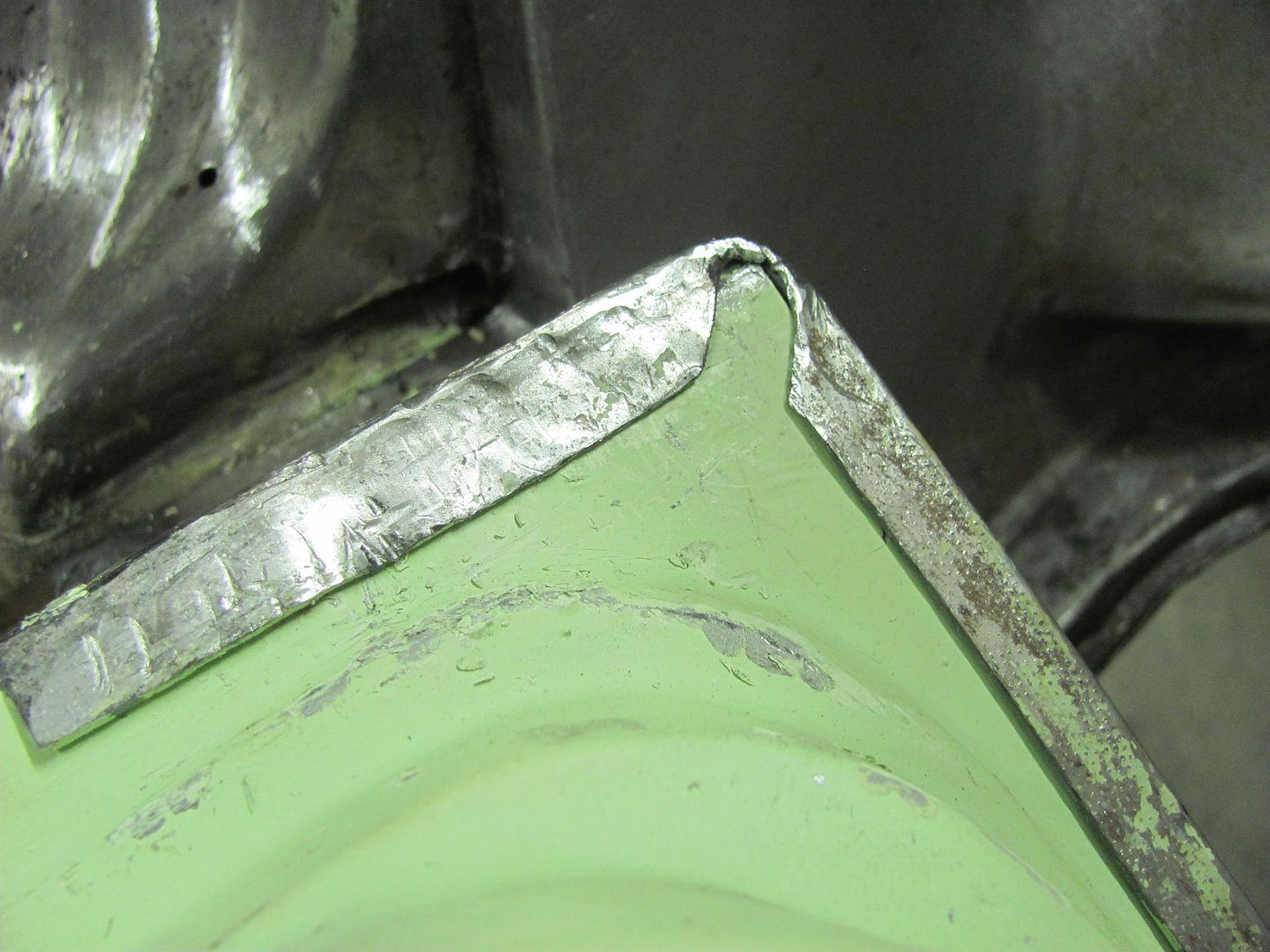
Once the welds by the tunnel relief were dressed, the sharp corners (inside and out) were removed to help prevent any cracks from starting..
Then on to fabbing up the other side..
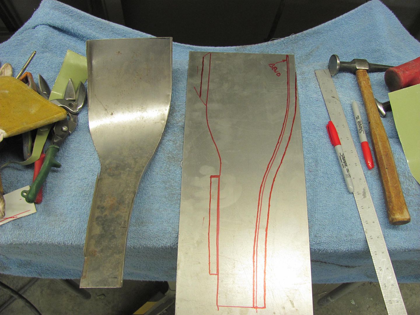
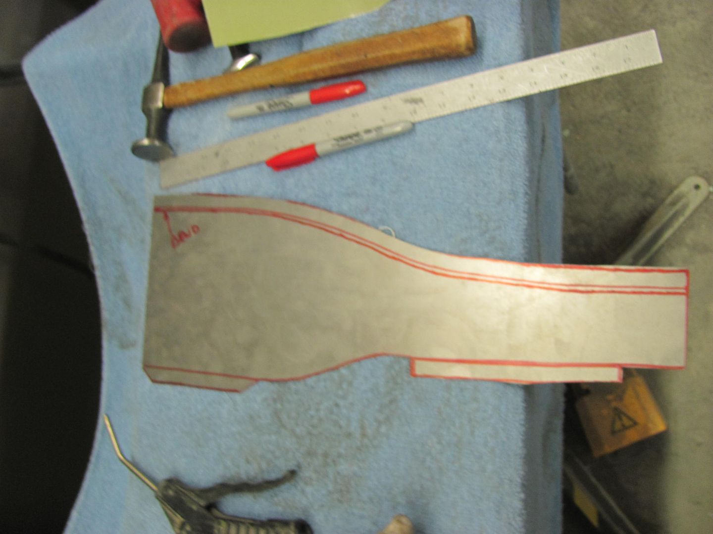
Kyle using the tipping die, I was relegated to bead roller powered option...
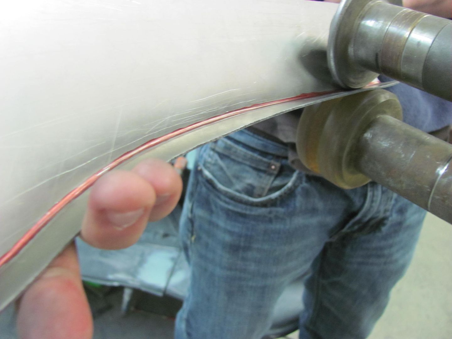
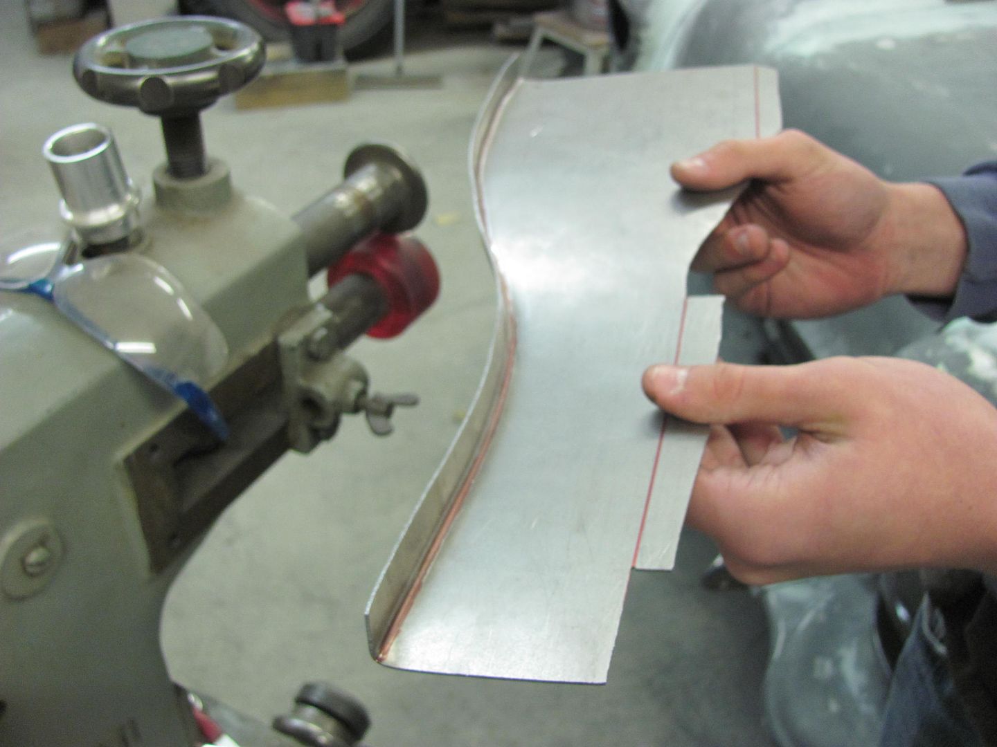
The two short flanges were bent in the press brake.. Then on to shrinking the flanges in the Erco. You'll have to visualize this one as we didn't get pictures.
Comparing the two...
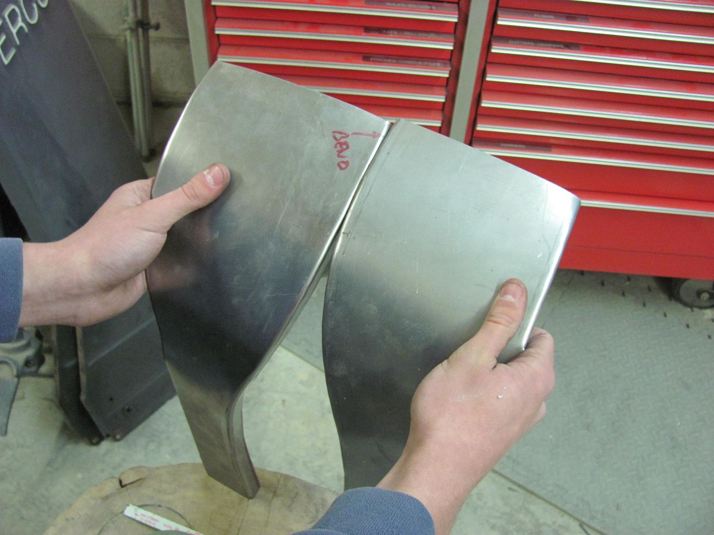
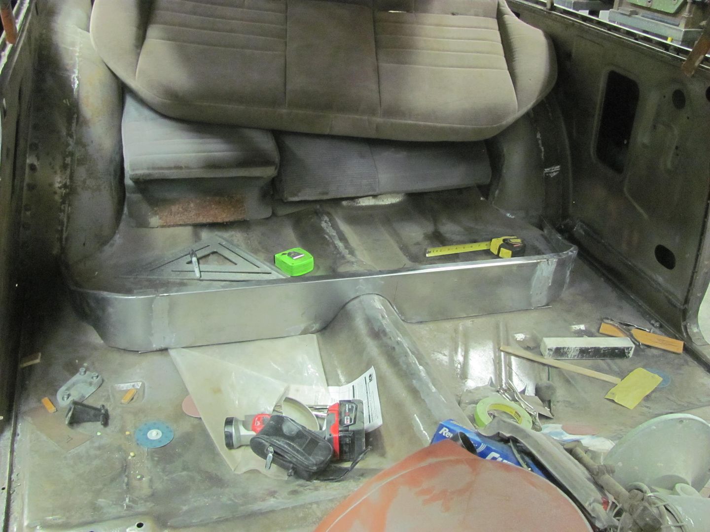
Test fit...
Seat cushion will need a widening kit..
Plug weld holes drilled and filled.....
Then attention is turned to duplicating a second half for the front divider panel for the rear seat.
Using the Erco kick shrinker....
Here's the fitment of the two seat panels together, all clamped up for welding..
Test fit..
Once the welds by the tunnel relief were dressed, the sharp corners (inside and out) were removed to help prevent any cracks from starting..
Then on to fabbing up the other side..
Kyle using the tipping die, I was relegated to bead roller powered option...
The two short flanges were bent in the press brake.. Then on to shrinking the flanges in the Erco. You'll have to visualize this one as we didn't get pictures.
Comparing the two...
Test fit...
Seat cushion will need a widening kit..
MP&C
Member
Thanks!
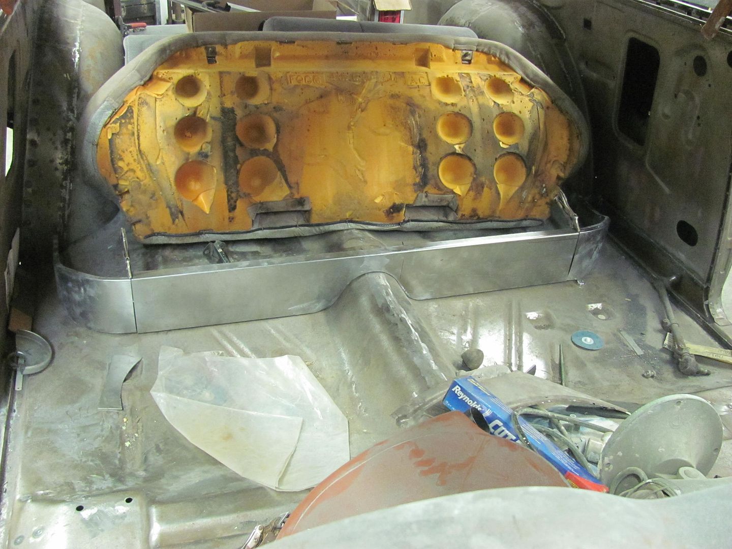
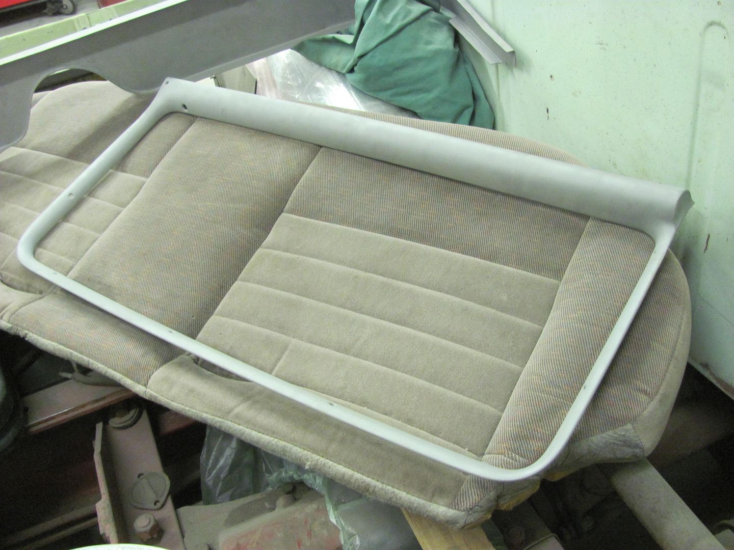
Our upholsterer stopped by the other day and discussed interior components. We are going to make some arm rests for the rear seat similar to what is used in the 55 convertible. To make room, we're going to keep the bottom seat cushion it's original width and just add foam to the corners to form the radius. So the sides for the seat risers were trimmed once more and test fitted...
The center of the seat riser was trimmed for the new size while leaving the flanges intact for later trimming..
Relief cuts added to tweak the radius, test fit into the car, and the top flanges clamped in place.. While clamped, the bottom flanges are trimmed for welding.
Copper backer made for welding up the corner..
All clamped up for the next one...
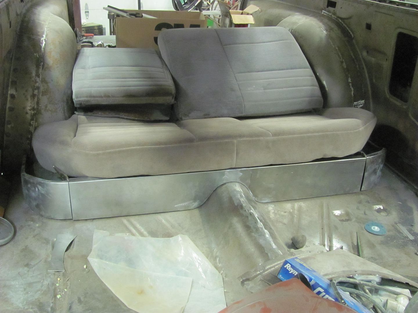
Seat riser completed, test fit of the rear seat...
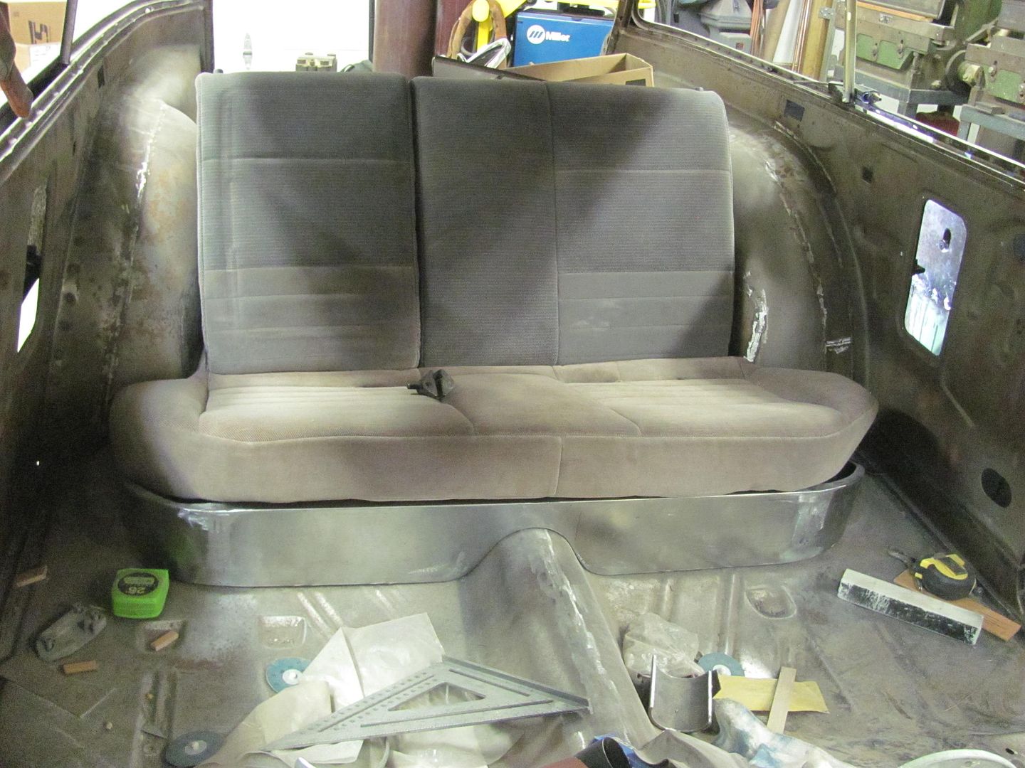
Corners of the lower cushion will have some foam added to fill out to a radius. Seat back will have some end cushions added to match the width of the lower seat..
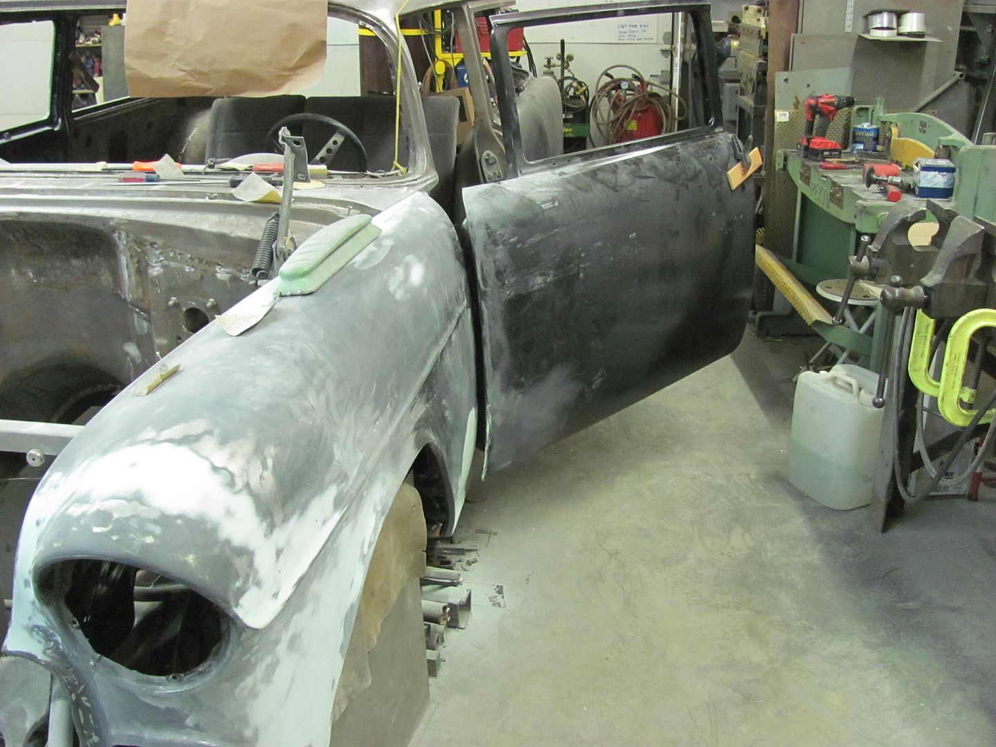
Blocking out of the driver's door is the last to do, and all the front sheet metal will be ready to come off for the next round of epoxy primer..
Our upholsterer stopped by the other day and discussed interior components. We are going to make some arm rests for the rear seat similar to what is used in the 55 convertible. To make room, we're going to keep the bottom seat cushion it's original width and just add foam to the corners to form the radius. So the sides for the seat risers were trimmed once more and test fitted...
The center of the seat riser was trimmed for the new size while leaving the flanges intact for later trimming..
Relief cuts added to tweak the radius, test fit into the car, and the top flanges clamped in place.. While clamped, the bottom flanges are trimmed for welding.
Copper backer made for welding up the corner..
All clamped up for the next one...
Seat riser completed, test fit of the rear seat...
Corners of the lower cushion will have some foam added to fill out to a radius. Seat back will have some end cushions added to match the width of the lower seat..
Blocking out of the driver's door is the last to do, and all the front sheet metal will be ready to come off for the next round of epoxy primer..
MP&C
Member
Spent the past few days at Dan Pate's. Well, it was only about a day and a half, but once you include the travel time...
To preface, I had posted a WTB ad for a 52" shear and Dan had sent me a PM about the one he had in his shop. It was getting replaced with a 6' machine. Dan's hosts a yearly metal shaping workshop and he suggested I come to his spring meet and pick it up from there. This conflicts with a mother's day event that I must attend every year (annual yard sale....I'm the furniture mover ), so I picked a window of opportunity that left minimal chance for the white powdery stuff falling from the sky. Namely, this past week. I departed Southern MD at about 12:45 am on Wednesday and drove through (rather un-eventful), arriving at Dan's at about 8:45 pm the same day. I recommend Mountain Dew and sunflower seeds for such an undertaking.
I'm looking forward to a break from the 55 wagon and to help out on some of the many challenging projects that Dan has shown us on the metalshaping sites over the years. So Dan, what have you got to work on? Oh, this car here over in the corner, he says......
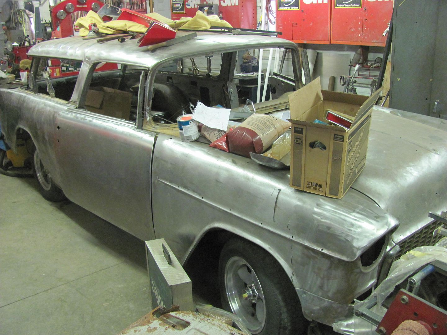
I restrained my enthusiasm as best I could in true Charlie Brown fashion

(just kidding Dan)
We walked down the hill to the shop the next morning and Dan had experienced some fitment issues with some of the panels on the 55 and asked that I take a look. RichardK showed up mid-morning and we proceeded to take measurements and cross diagonals nine ways to Sunday. We verified these to a sample car sitting out in the yard, and still didn't have that ah-ha moment. Everything we checked seemed to be within factory specs, although that was pretty loose in 1955.
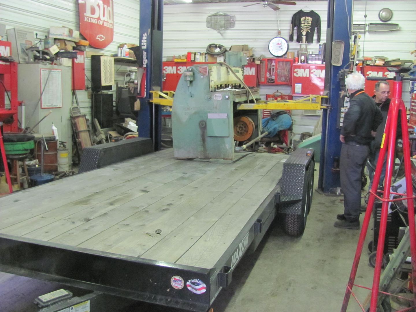
My plans were to work around the shop for a day, load up the shear the next morning (Friday), and leave around noon. I have a cousin, Nancy E. Rueckert, who lives in Litchfield, MN. She had been in an industrial accident at work and was now paralyzed, and I was going to visit her that evening. Dan wisely pointed out that we should load the shear to have everything ready to go, and then worry about other shop activity.
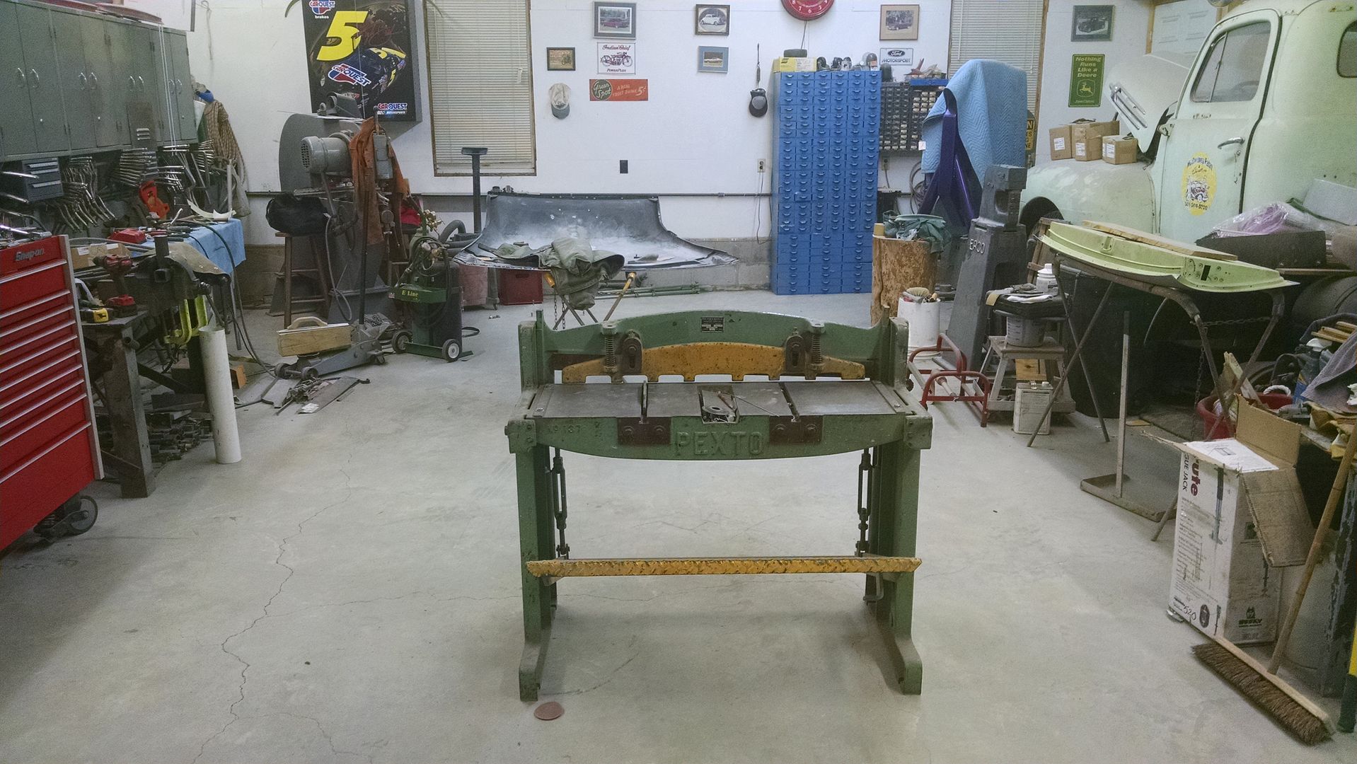
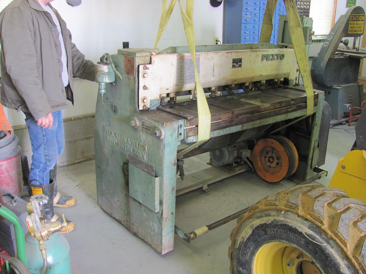
So here is the shear prior to the John Deere moving it...
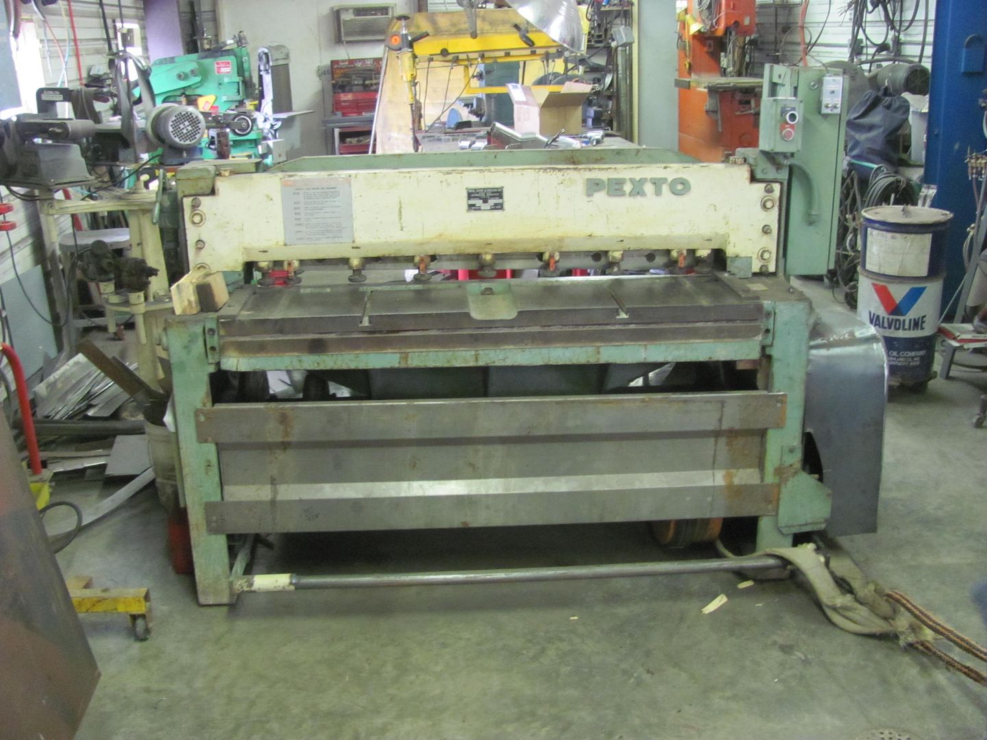
...and for anyone with sufficient space available for one of these, Dan has this nifty equipment hoist...
As there was some rain forecast for the east coast on Friday, the shear got some appropriate attention..
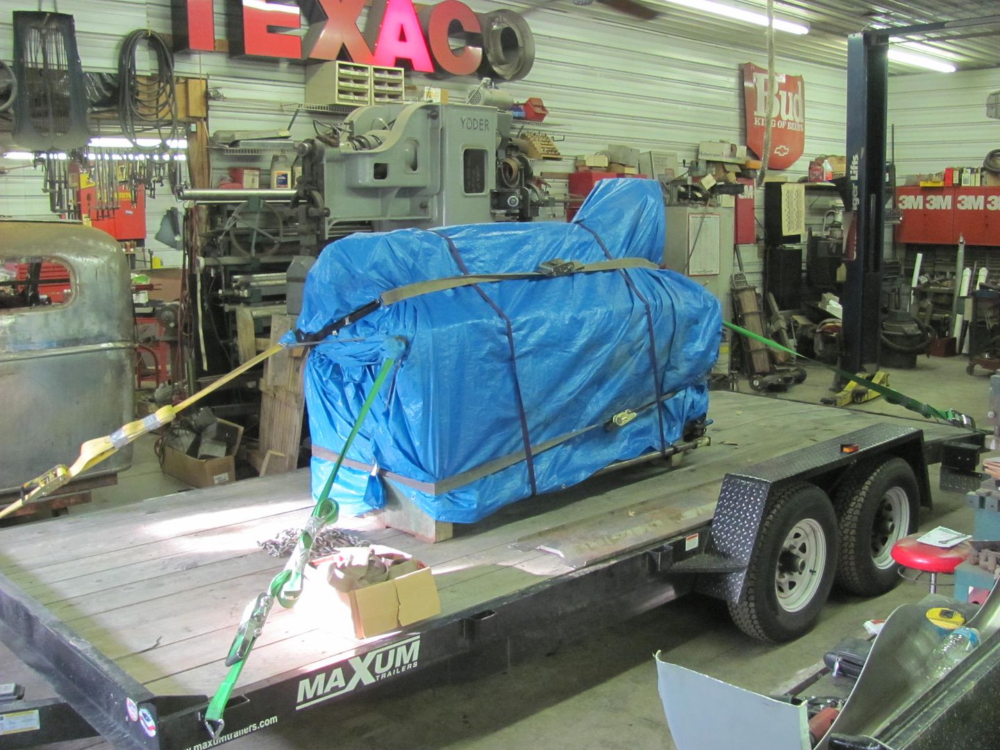
It was about time for me to get cleaned up for the visit to my cousin's, and Richard mentioned that he had a buddy who lived in Howard Lake, a short drive before Litchfield. Since the truck was hooked to the trailer, he offered to drive me to Howard Lake, where he could visit his friend and I could continue to Litchfield. What a true gentleman, and as I've seen with Dan, genuine MN hospitality.
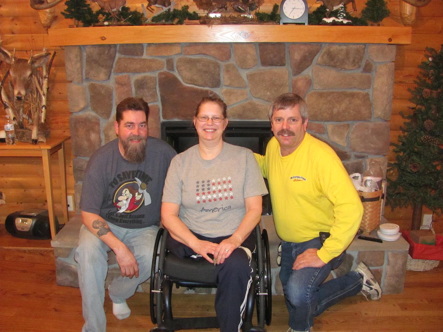
Had a nice visit with Nancy, and I think our conversations got carried away that when I looked at my watch I was worried Richard would put out an APB on his car :bounce:
Here's Nancy with her husband Dan.. (to eliminate confusion, let's call him Dan2)
I made it back to Howard Lake and got a chance to meet Richard's friend, Jan Gilmer. He's well known in the Midget racing world and even more so, since his retirement, in his meticulous reproductions of 1/4 scale RC replicas. Here are some pictures of a restored Midget from 1956...
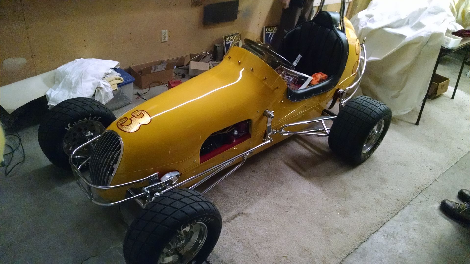

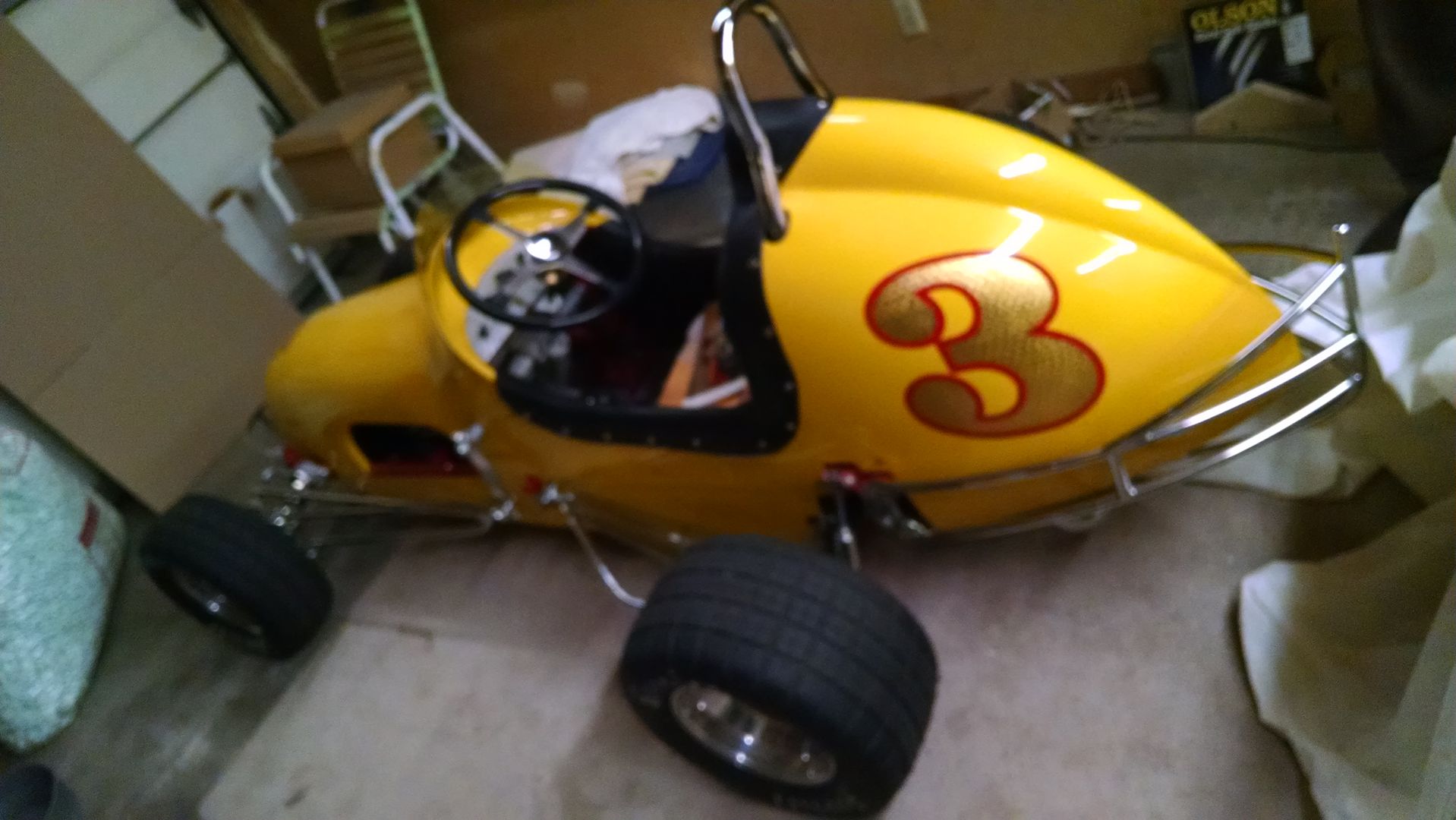
.....along with Richard's thread posted here about the body he built for the car.. A work of art to say the least.
http://www.allmetalshaping.com/showthread.php?t=2768
And here are some links on Jan Gilmer for those interested...
http://www.herald-journal.com/archives/2012/stories/Gilmer-cars-Australia.html
http://www.quarterscalelegends.com/gilmer/gilmer.htm
Jan has a small machinist shop and still produces amazingly accurate 1/4 scale reproductions to this day. They are highly sought after, and after seeing them in person, I can see why.
Richard and I returned to Dan's with only one close call with a couple of Minnesota's 4 legged Bambi creatures.. Even as late as it was, Dan greeted me and I think we talked of more metalshaping stories for the next couple hours. My day job has me heading to Oahu in the near future, and he was telling me of his visit to the only Pullmax owner on the island of Oahu, let's call him George. So I hope to meet up with George on my next visit to HI.
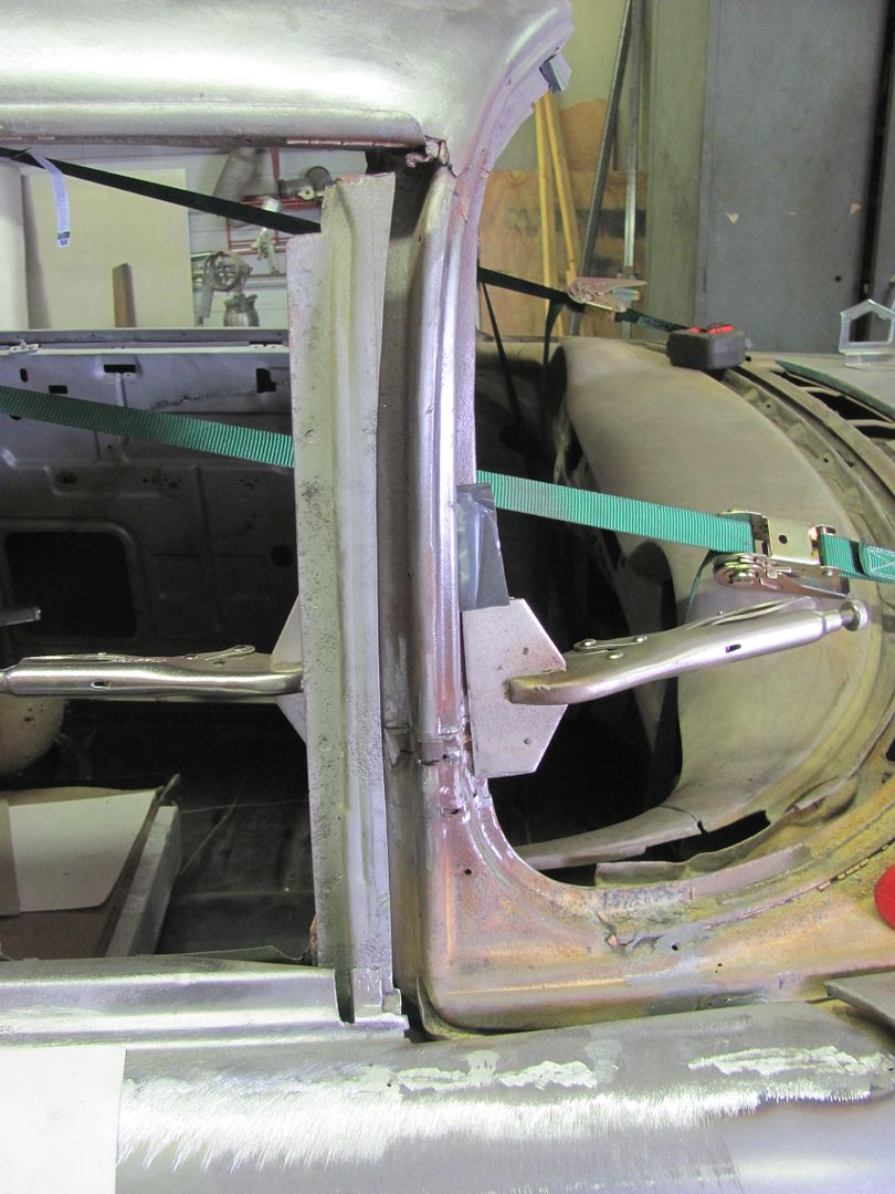
After breakfast we headed down to Dan's shop. Back on the 55, it wasn't until we took the height dimension of the windshield that we came up with the answer, there was a quite a difference there. Dan had installed a new roof on this from a donor car, one of the seams being in the A post. We found a slight excess in vertical made for quite a jump in the windshield opening. So with a bit of slicing, our height adjustment at the a-pillar made for quite an improvement and a more consistent and parallel gap to the door behind it..
Since I wasn't going to be at Dan's spring event, he spent quite a bit of time showing me some shop tricks...
Band Saw "guide" for cutting convex shapes on the band saw... Slides into the blade and gets bolted to the table.... Essentially moves the table surface for those oddball shapes that don't fit the table..
Linear stretch dies for the Pullmax....
The cantilevered and jack bolted design allows you to adjust the stretch for a tight radius, and the pointed ends allow you to get into the corner as tightly as needed...
Adjustable backstop for thinning a panel for sharper bends
Delrin die to use for panel beading.. in conjunction with MDF forms.. (partially unscrewed to show threads)
"tank roll" or 45* radius tipping dies for the Pullmax... 3 pieces were laser cut in 1/4" stock and welded together to form the 3/4 shank..
Flanging/step die using an MDF guide....
Imagine this for a bed side...
At this time I think my target departure time had come and gone.. But no visit to Dan's shop is complete until you've used the Yoder....
All packed up, ready to head east.
I made mention to Dan that Friday the 13th was not a good day to travel. About halfway down I39 in Indiana proved this. I had just passed by a semi and pulled back into the slow lane in front of him when I noticed a set of headlights coming toward me.... in the fast lane I had just moved out of. I made out of that rather lucky. About a mile down the road some scattered auto debris and one car against the center divider showed they weren't as lucky. Everyone was OK, and I think most of the damage was from them swerving to miss the clown heading north in the southbound lane. Well upon arriving home, the rain added to the snow from last week has made my driveway a swamp. Looks like we will unload the trailer when this has dried up a bit.
To preface, I had posted a WTB ad for a 52" shear and Dan had sent me a PM about the one he had in his shop. It was getting replaced with a 6' machine. Dan's hosts a yearly metal shaping workshop and he suggested I come to his spring meet and pick it up from there. This conflicts with a mother's day event that I must attend every year (annual yard sale....I'm the furniture mover
), so I picked a window of opportunity that left minimal chance for the white powdery stuff falling from the sky. Namely, this past week. I departed Southern MD at about 12:45 am on Wednesday and drove through (rather un-eventful), arriving at Dan's at about 8:45 pm the same day. I recommend Mountain Dew and sunflower seeds for such an undertaking. I'm looking forward to a break from the 55 wagon and to help out on some of the many challenging projects that Dan has shown us on the metalshaping sites over the years. So Dan, what have you got to work on? Oh, this car here over in the corner, he says......
I restrained my enthusiasm as best I could in true Charlie Brown fashion
(just kidding Dan)
We walked down the hill to the shop the next morning and Dan had experienced some fitment issues with some of the panels on the 55 and asked that I take a look. RichardK showed up mid-morning and we proceeded to take measurements and cross diagonals nine ways to Sunday. We verified these to a sample car sitting out in the yard, and still didn't have that ah-ha moment. Everything we checked seemed to be within factory specs, although that was pretty loose in 1955.
My plans were to work around the shop for a day, load up the shear the next morning (Friday), and leave around noon. I have a cousin, Nancy E. Rueckert, who lives in Litchfield, MN. She had been in an industrial accident at work and was now paralyzed, and I was going to visit her that evening. Dan wisely pointed out that we should load the shear to have everything ready to go, and then worry about other shop activity.
So here is the shear prior to the John Deere moving it...
...and for anyone with sufficient space available for one of these, Dan has this nifty equipment hoist...
As there was some rain forecast for the east coast on Friday, the shear got some appropriate attention..
It was about time for me to get cleaned up for the visit to my cousin's, and Richard mentioned that he had a buddy who lived in Howard Lake, a short drive before Litchfield. Since the truck was hooked to the trailer, he offered to drive me to Howard Lake, where he could visit his friend and I could continue to Litchfield. What a true gentleman, and as I've seen with Dan, genuine MN hospitality.
Had a nice visit with Nancy, and I think our conversations got carried away that when I looked at my watch I was worried Richard would put out an APB on his car :bounce:
Here's Nancy with her husband Dan.. (to eliminate confusion, let's call him Dan2)
I made it back to Howard Lake and got a chance to meet Richard's friend, Jan Gilmer. He's well known in the Midget racing world and even more so, since his retirement, in his meticulous reproductions of 1/4 scale RC replicas. Here are some pictures of a restored Midget from 1956...
.....along with Richard's thread posted here about the body he built for the car.. A work of art to say the least.
http://www.allmetalshaping.com/showthread.php?t=2768
And here are some links on Jan Gilmer for those interested...
http://www.herald-journal.com/archives/2012/stories/Gilmer-cars-Australia.html
http://www.quarterscalelegends.com/gilmer/gilmer.htm
Jan has a small machinist shop and still produces amazingly accurate 1/4 scale reproductions to this day. They are highly sought after, and after seeing them in person, I can see why.
Richard and I returned to Dan's with only one close call with a couple of Minnesota's 4 legged Bambi creatures.. Even as late as it was, Dan greeted me and I think we talked of more metalshaping stories for the next couple hours. My day job has me heading to Oahu in the near future, and he was telling me of his visit to the only Pullmax owner on the island of Oahu, let's call him George. So I hope to meet up with George on my next visit to HI.
After breakfast we headed down to Dan's shop. Back on the 55, it wasn't until we took the height dimension of the windshield that we came up with the answer, there was a quite a difference there. Dan had installed a new roof on this from a donor car, one of the seams being in the A post. We found a slight excess in vertical made for quite a jump in the windshield opening. So with a bit of slicing, our height adjustment at the a-pillar made for quite an improvement and a more consistent and parallel gap to the door behind it..
Since I wasn't going to be at Dan's spring event, he spent quite a bit of time showing me some shop tricks...
Band Saw "guide" for cutting convex shapes on the band saw... Slides into the blade and gets bolted to the table.... Essentially moves the table surface for those oddball shapes that don't fit the table..
Linear stretch dies for the Pullmax....
The cantilevered and jack bolted design allows you to adjust the stretch for a tight radius, and the pointed ends allow you to get into the corner as tightly as needed...
Adjustable backstop for thinning a panel for sharper bends
Delrin die to use for panel beading.. in conjunction with MDF forms.. (partially unscrewed to show threads)
"tank roll" or 45* radius tipping dies for the Pullmax... 3 pieces were laser cut in 1/4" stock and welded together to form the 3/4 shank..
Flanging/step die using an MDF guide....
Imagine this for a bed side...
At this time I think my target departure time had come and gone.. But no visit to Dan's shop is complete until you've used the Yoder....
All packed up, ready to head east.
I made mention to Dan that Friday the 13th was not a good day to travel. About halfway down I39 in Indiana proved this. I had just passed by a semi and pulled back into the slow lane in front of him when I noticed a set of headlights coming toward me.... in the fast lane I had just moved out of. I made out of that rather lucky. About a mile down the road some scattered auto debris and one car against the center divider showed they weren't as lucky. Everyone was OK, and I think most of the damage was from them swerving to miss the clown heading north in the southbound lane. Well upon arriving home, the rain added to the snow from last week has made my driveway a swamp. Looks like we will unload the trailer when this has dried up a bit.
MP&C
Member
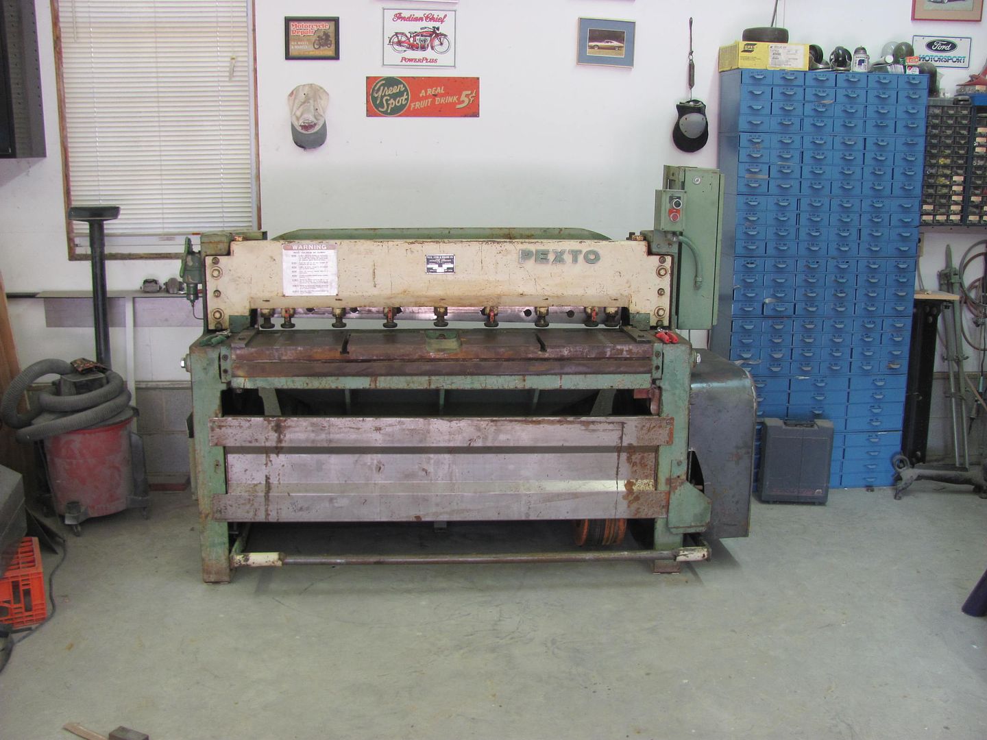
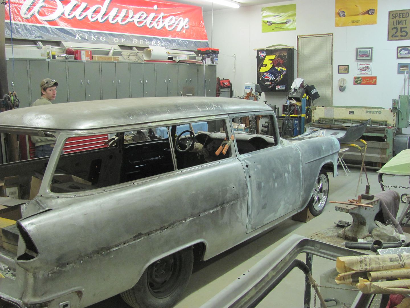
Last night's shop progress. Got the 55 moved into the paint booth....
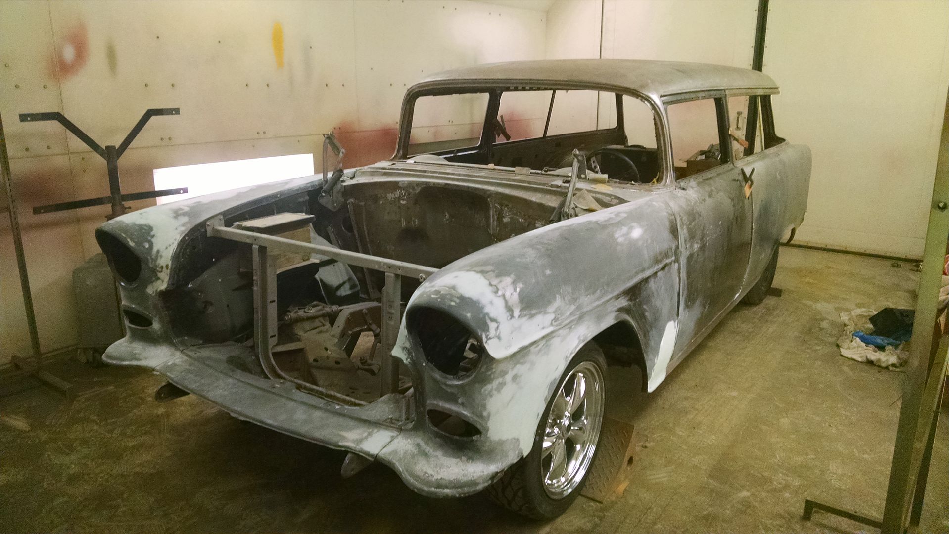
.....but only temporarily, not quite ready for paint yet.. Shuffling some stuff around to make room for bringing in the new shear on Saturday, and needed the car out of the way. The new shear is just shy of 7 feet long, so it wouldn't fit in the same spot as the old one without moving something else as well. In measuring the tool box, it looked like a good fit in that spot, so moving it and the kick shrinker will make a better spot for the new shear against the back wall.
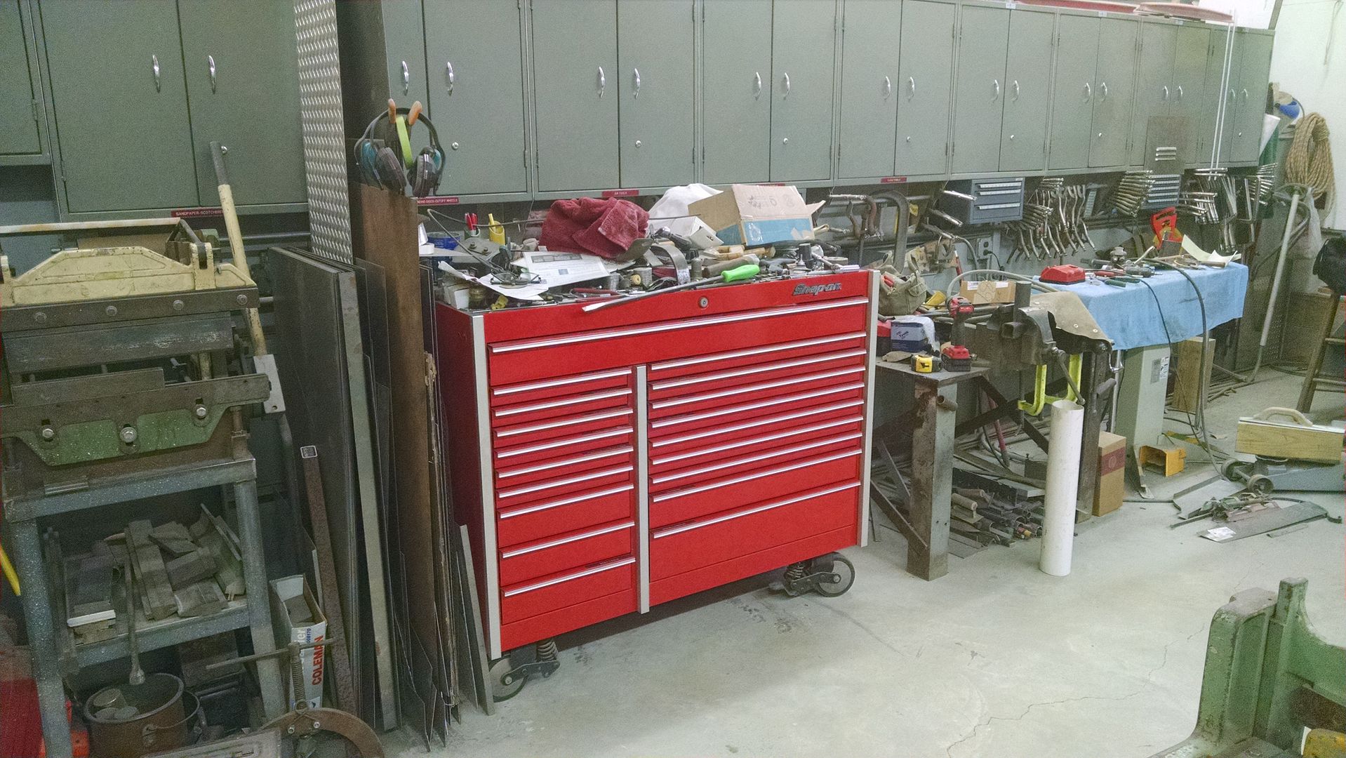
.....and as we haven't used the radial arm drill press in over a year, I think that's getting ready to go on CL to make room for the planishing hammer, when that gets finished up..
.....but only temporarily, not quite ready for paint yet.. Shuffling some stuff around to make room for bringing in the new shear on Saturday, and needed the car out of the way. The new shear is just shy of 7 feet long, so it wouldn't fit in the same spot as the old one without moving something else as well. In measuring the tool box, it looked like a good fit in that spot, so moving it and the kick shrinker will make a better spot for the new shear against the back wall.
.....and as we haven't used the radial arm drill press in over a year, I think that's getting ready to go on CL to make room for the planishing hammer, when that gets finished up..
MP&C
Member
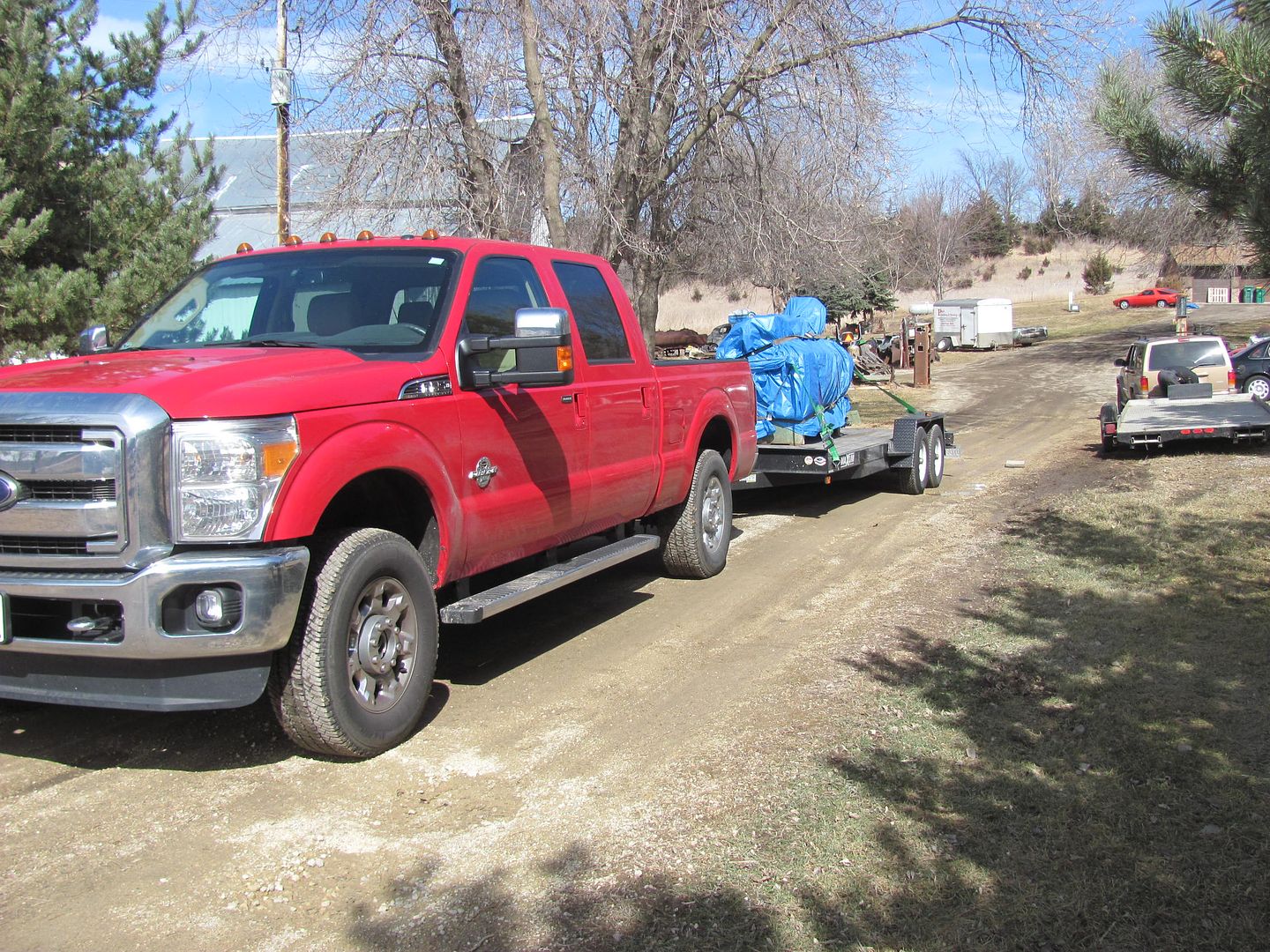
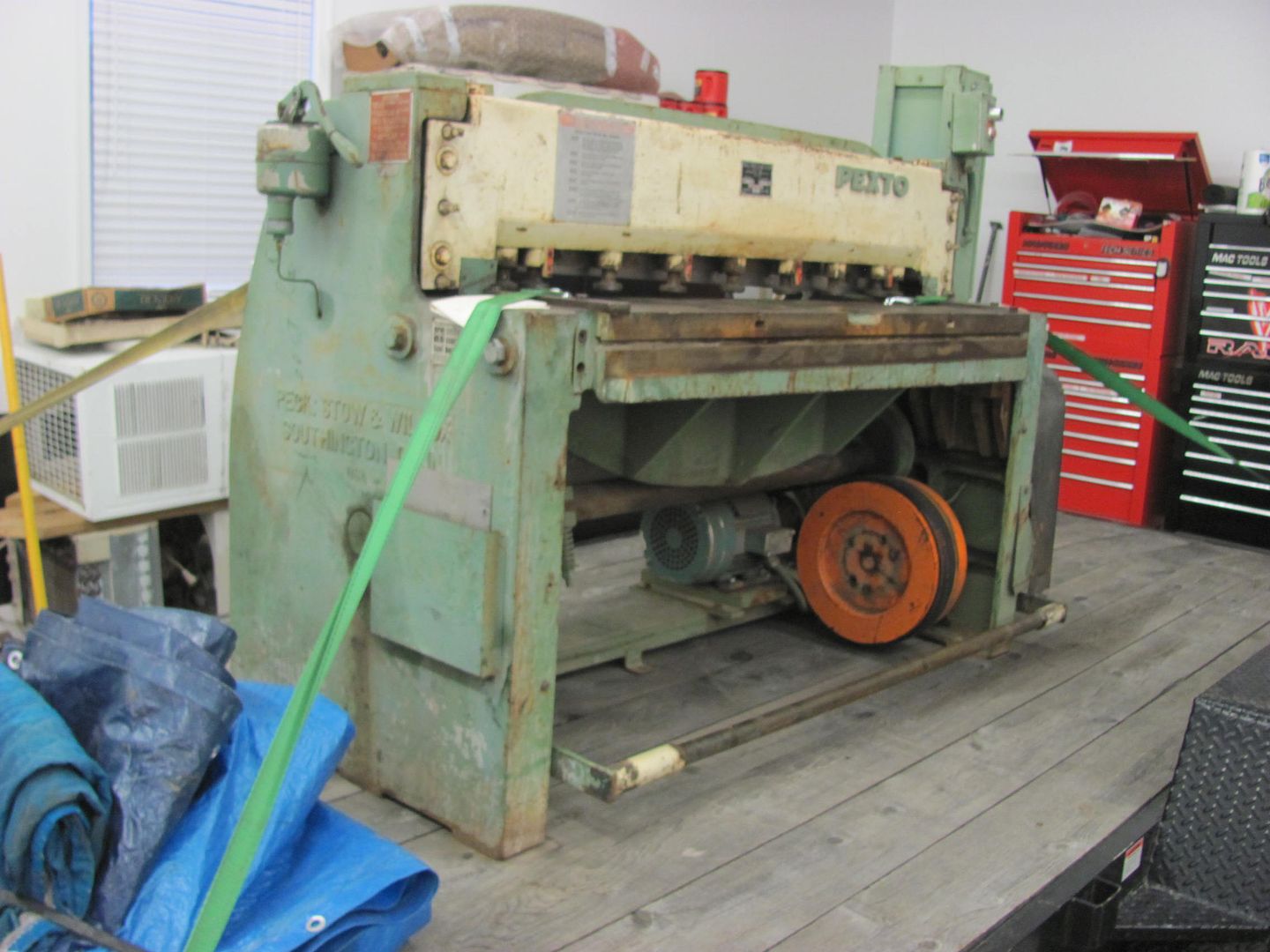
This past Saturday morning started at my brother-in-laws to pick up the new shear. It's been parked in his garage since the week before while my driveway has been drying out..
Here's his El Camino project, narrowing the frame rails in the rear....
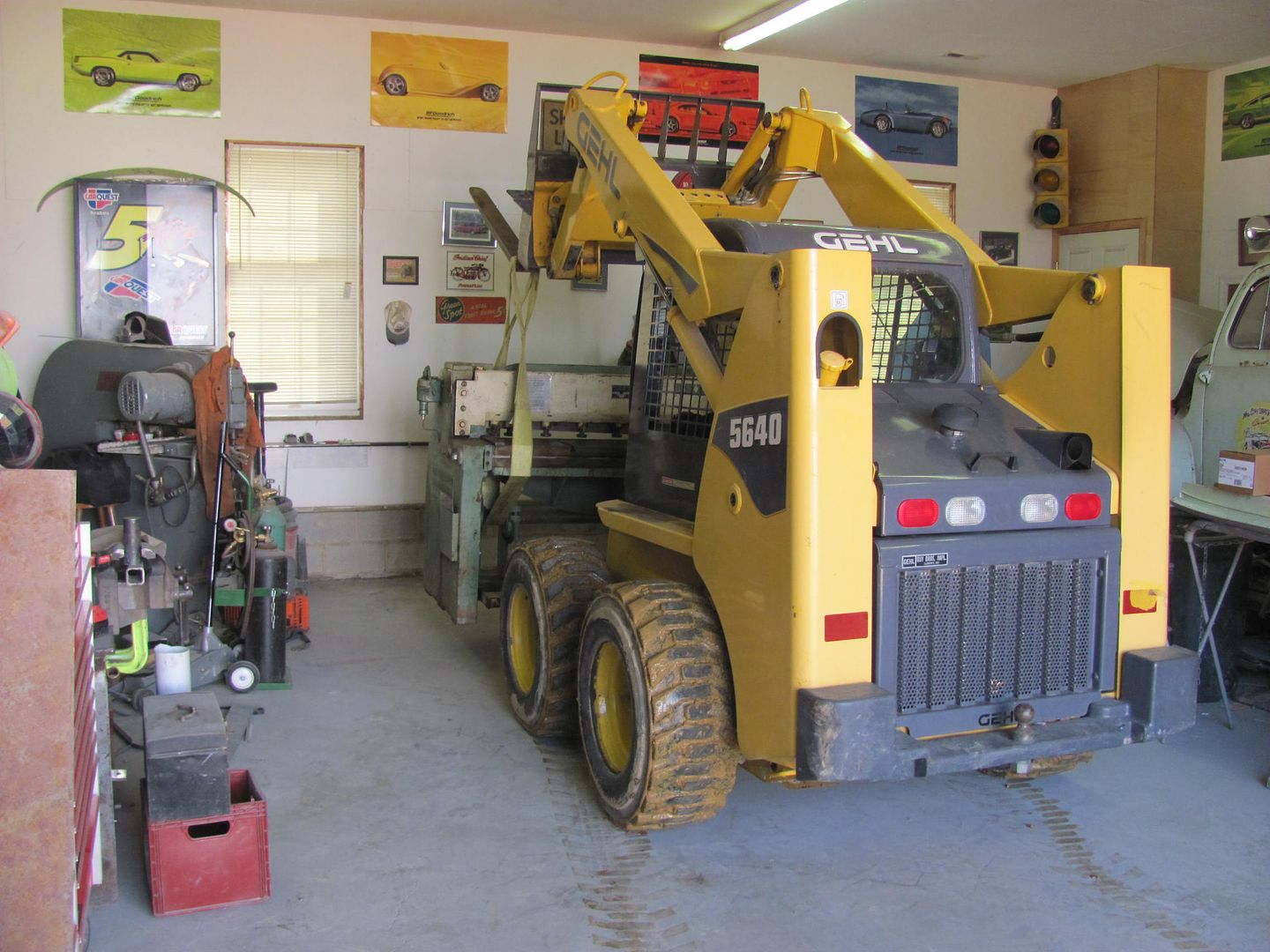
One of the neighbors a few miles down the road has a Pettibone forklift. I had him lined up to help lift the shear off the trailer today. He made it about 1/4 mile and had the brakes locking up and frying, so we had to back up and punt. Another buddy has a skid steer with the fork attachment, but the shear was on his trailer. So we dropped off the trailer/shear at the shop, went and got another trailer and picked up the skid steer.. I will say this shear is about at the limits of the lifting capacity of this skid steer, the back end was trying to go airborne when lifting it off the trailer. So we inched it up in the air and then pulled the trailer out from under it. Here's the placement...
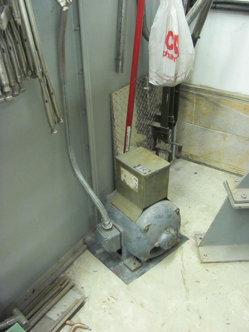
Next, the electrical hookup...
Here's his El Camino project, narrowing the frame rails in the rear....
One of the neighbors a few miles down the road has a Pettibone forklift. I had him lined up to help lift the shear off the trailer today. He made it about 1/4 mile and had the brakes locking up and frying, so we had to back up and punt. Another buddy has a skid steer with the fork attachment, but the shear was on his trailer. So we dropped off the trailer/shear at the shop, went and got another trailer and picked up the skid steer.. I will say this shear is about at the limits of the lifting capacity of this skid steer, the back end was trying to go airborne when lifting it off the trailer. So we inched it up in the air and then pulled the trailer out from under it. Here's the placement...
Next, the electrical hookup...
MP&C
Member
Got some electrical work done last night, wired up the phase converter first, checked the voltage, then wired up the shear..
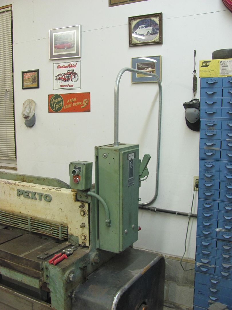
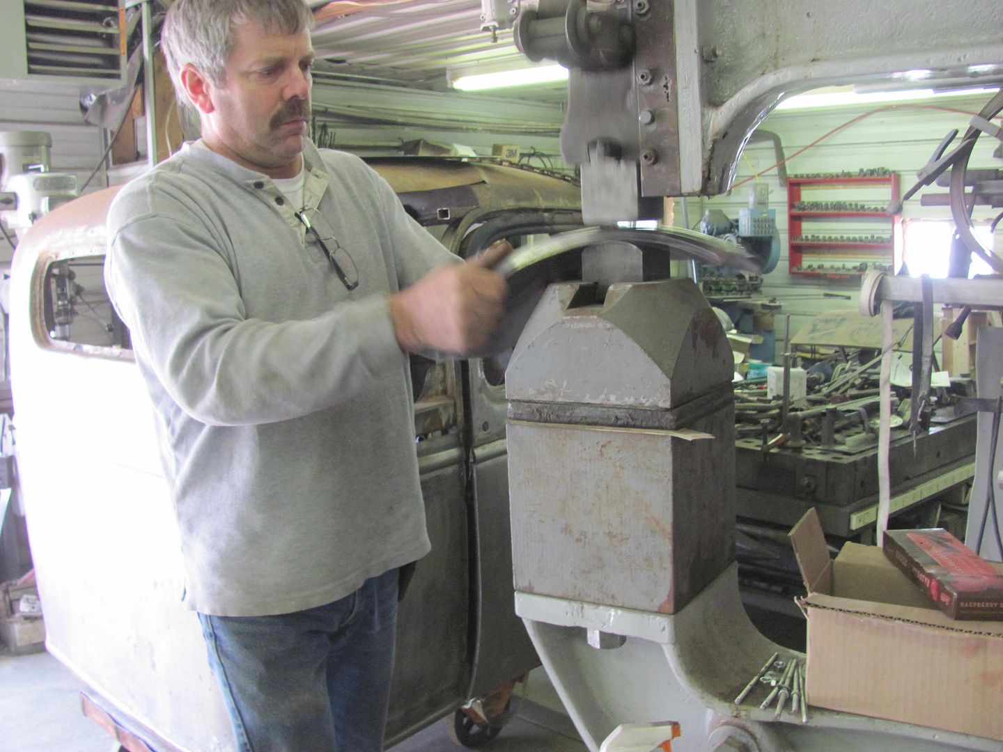
When I went to Minnesota to pick up the shear, I noticed that Dan had a couple pair of snips laying on the shear.. Didn't put two and two together at first.
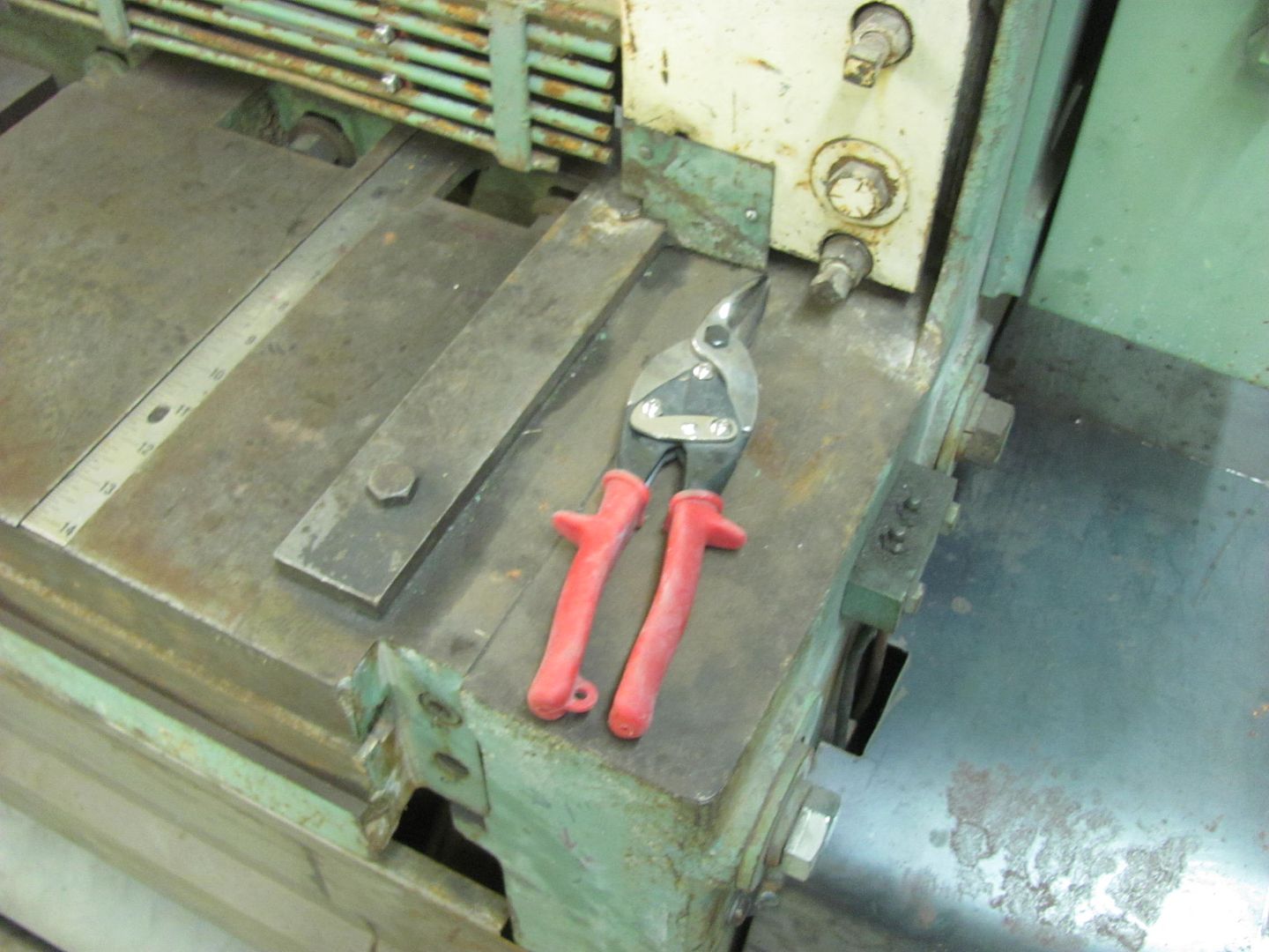
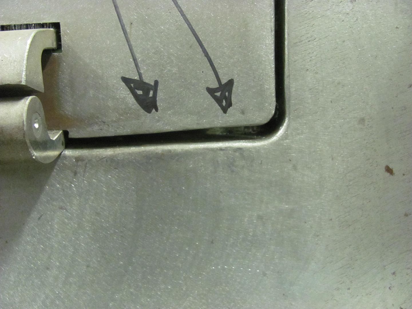
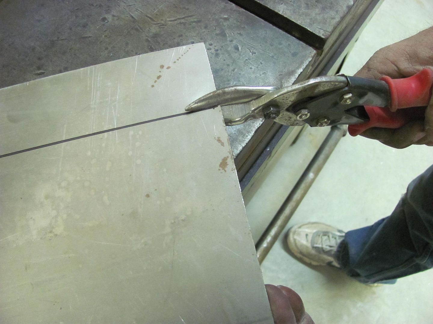
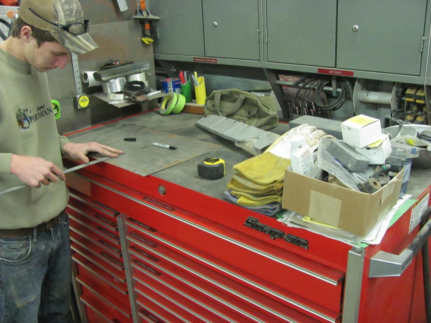
He had the shear installed without the back gauge due to the space requirements, and I had even less shop room than he did. This is where the snips come in. Mark your panel for the cut line...
Use the red shears to make a slight cut on the right side of the panel....
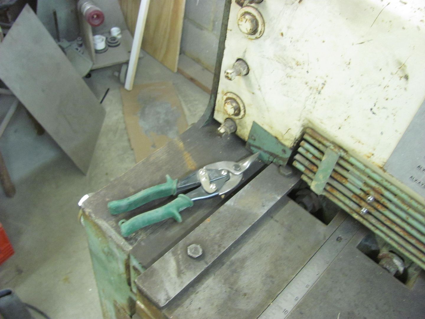
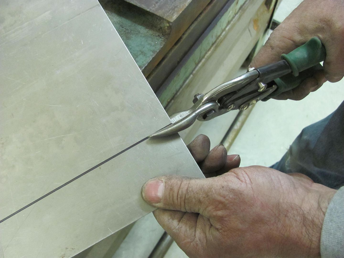
.....and the green shears to make a slight cut on the left side...
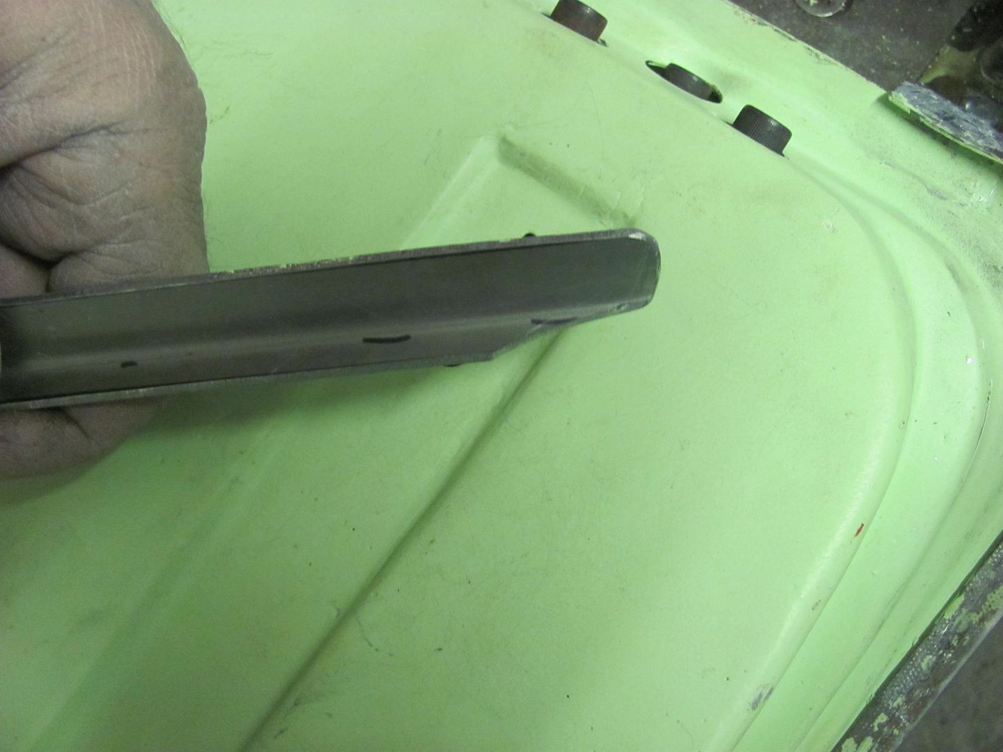
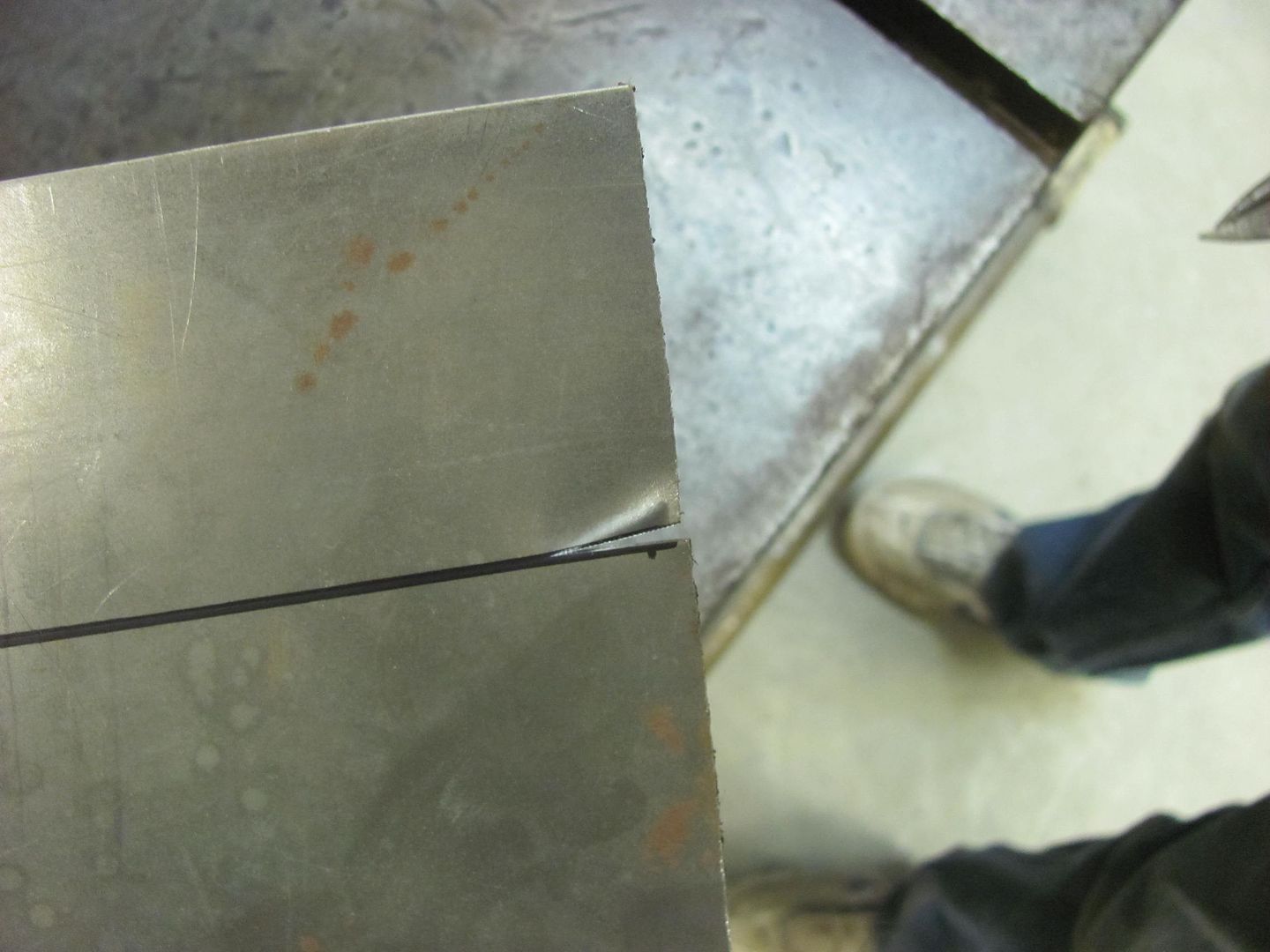
Now you have the cut line "marked" on both ends...
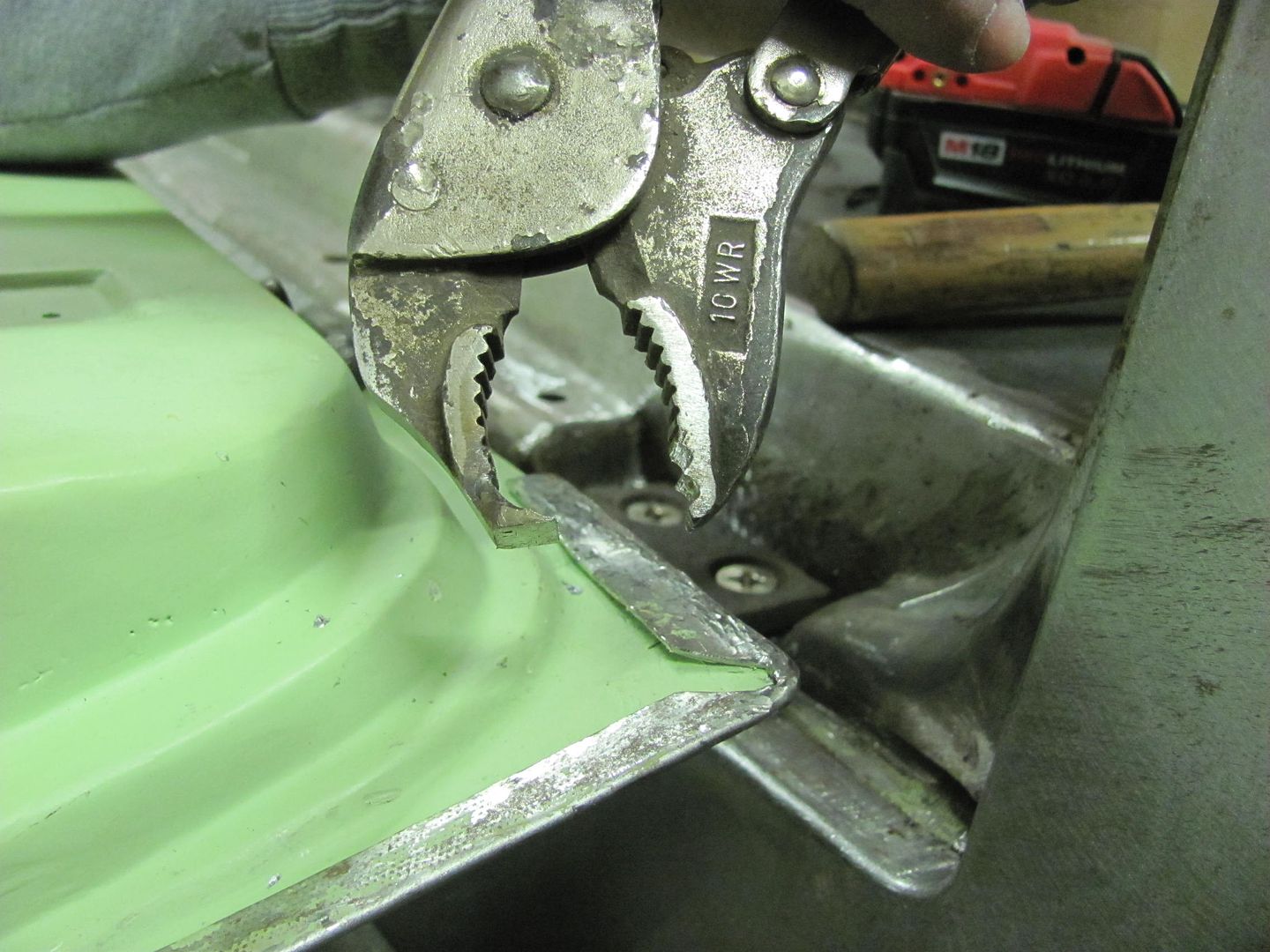
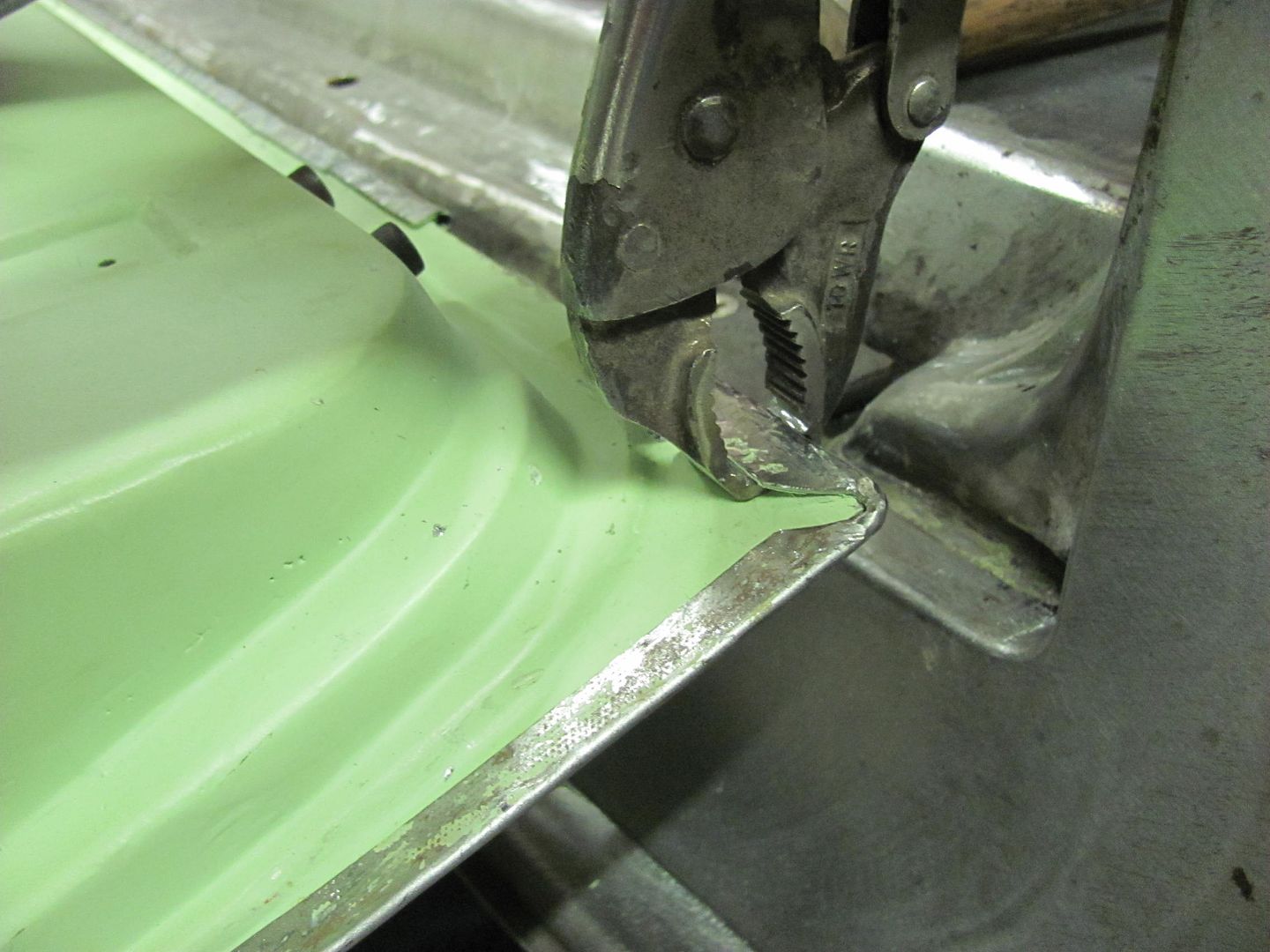
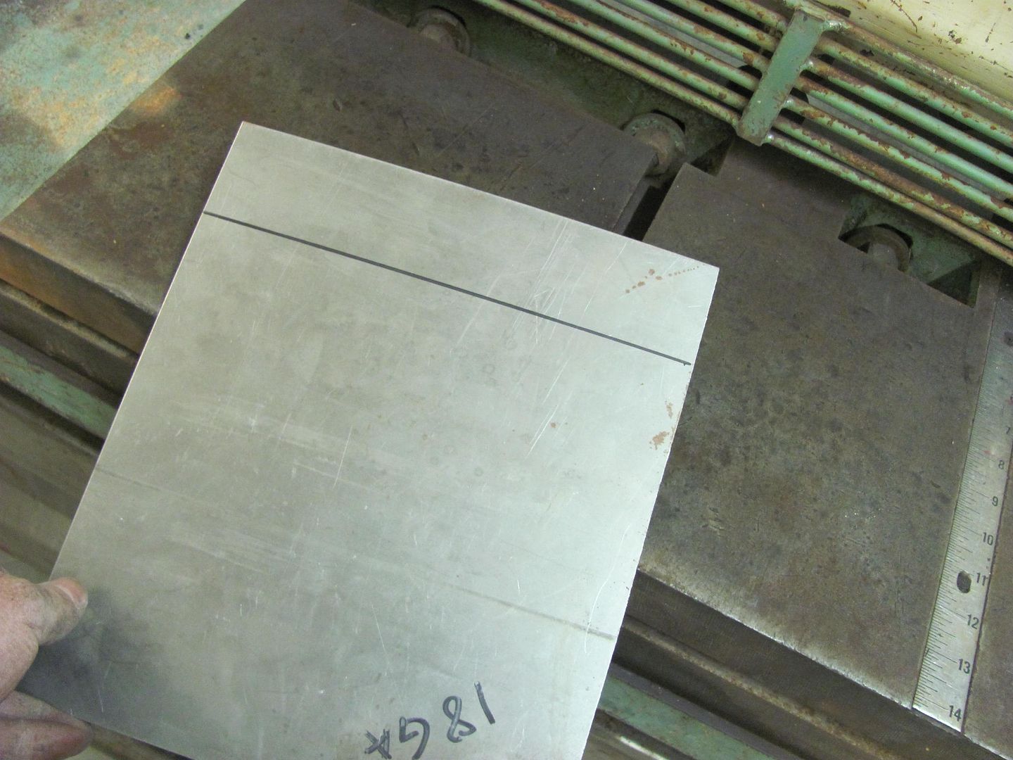
Slide the panel into the shear just past the cut edge, then gently pull back until it stops against the lower blade...
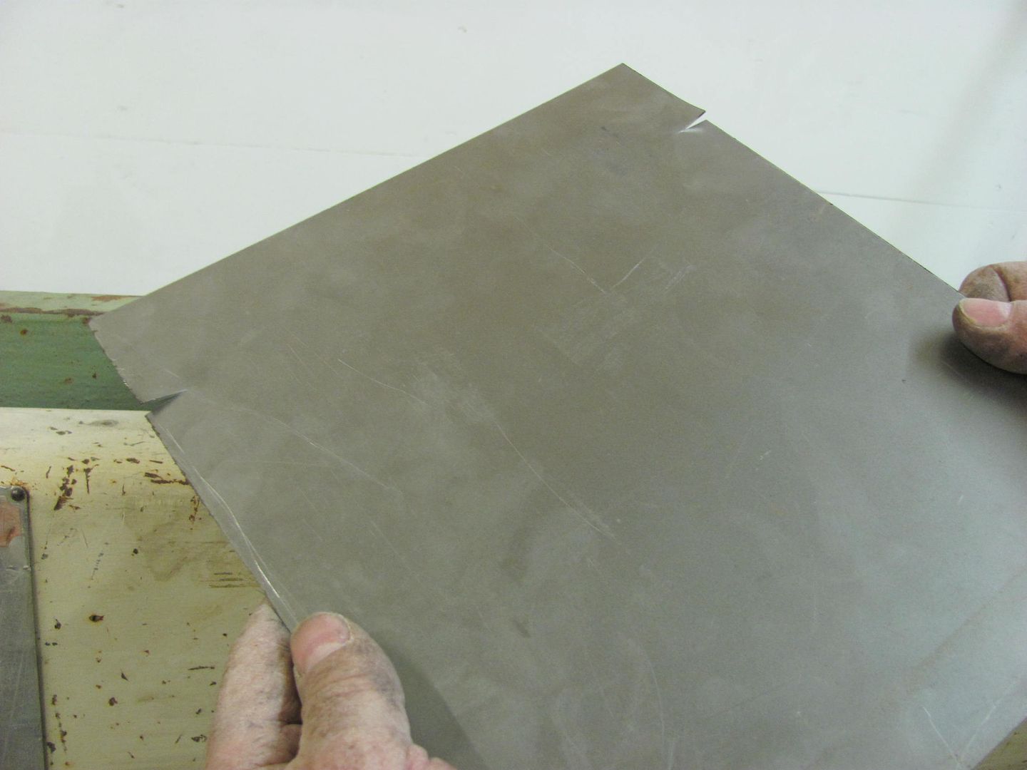
Now shear. No back gauge or second person to help sight in a full width sheet needed.. No fuss no muss. Thanks to Dan for the helpful hint!
While I've been playing electrician, Kyle has been plugging along in getting various pieces media blasted so they can get epoxy primed....
When I went to Minnesota to pick up the shear, I noticed that Dan had a couple pair of snips laying on the shear.. Didn't put two and two together at first.
He had the shear installed without the back gauge due to the space requirements, and I had even less shop room than he did. This is where the snips come in. Mark your panel for the cut line...
Use the red shears to make a slight cut on the right side of the panel....
.....and the green shears to make a slight cut on the left side...
Now you have the cut line "marked" on both ends...
Slide the panel into the shear just past the cut edge, then gently pull back until it stops against the lower blade...
Now shear. No back gauge or second person to help sight in a full width sheet needed.. No fuss no muss. Thanks to Dan for the helpful hint!
While I've been playing electrician, Kyle has been plugging along in getting various pieces media blasted so they can get epoxy primed....
MP&C
Member
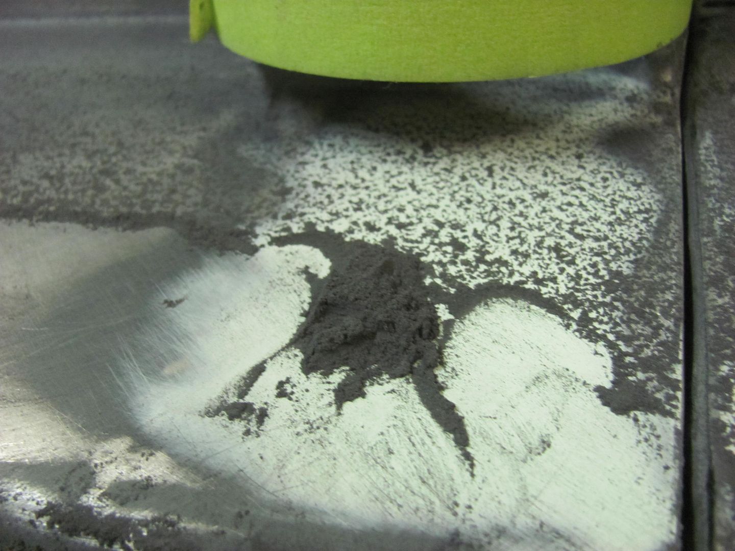
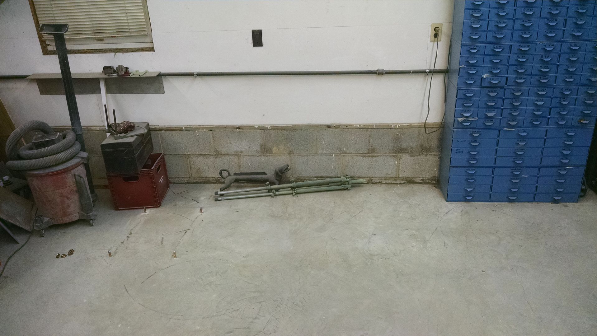
While the wagon was still in the booth, the floor and welding table got the semi-annual cleaning....
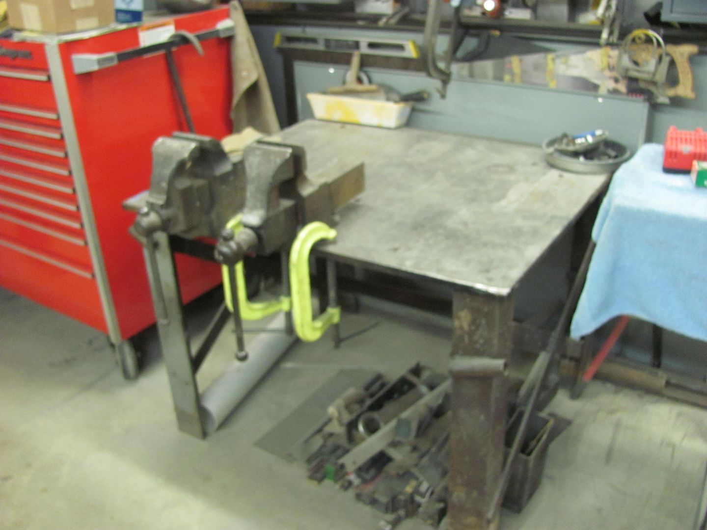
even the top of the tool box...
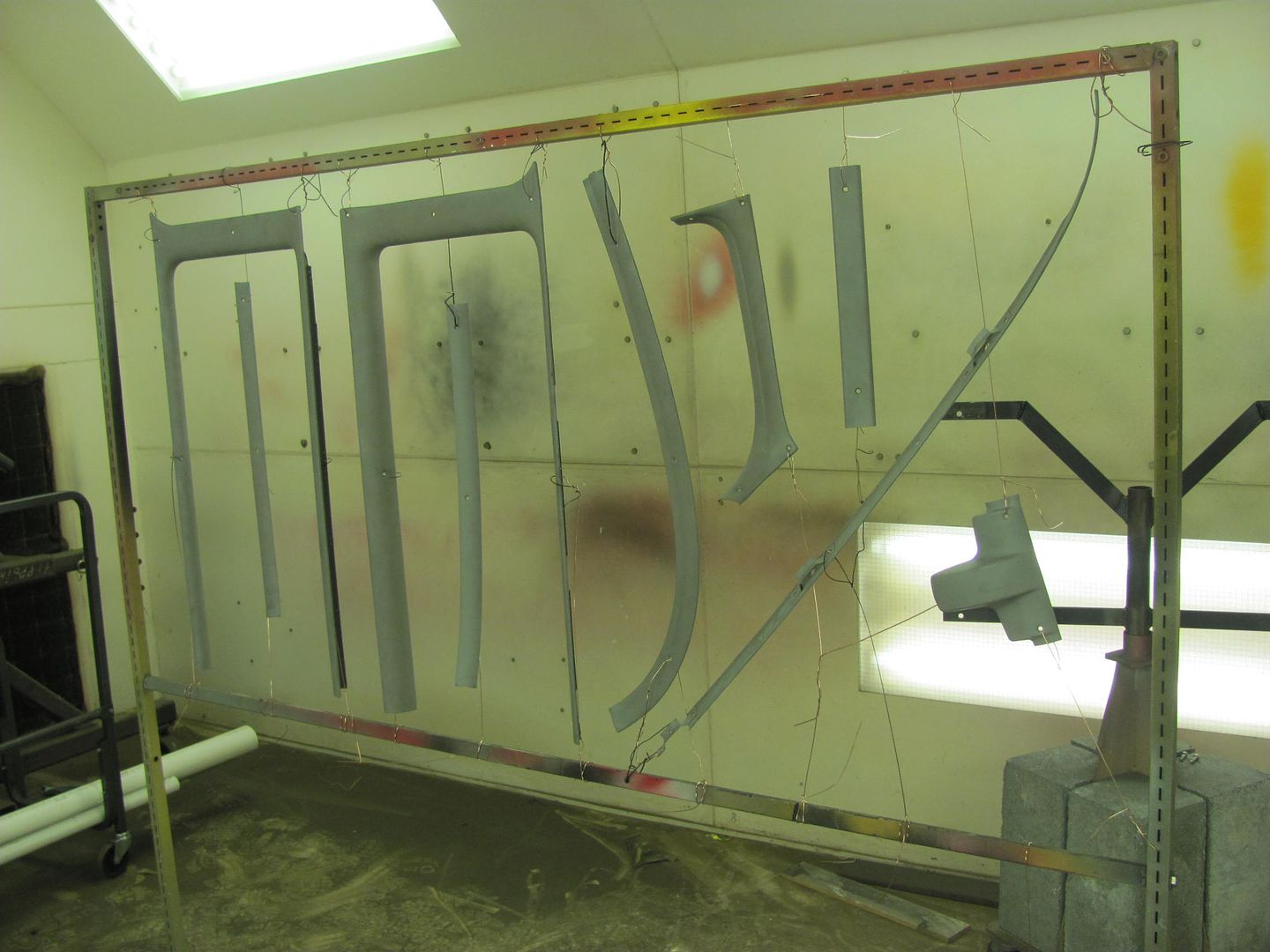
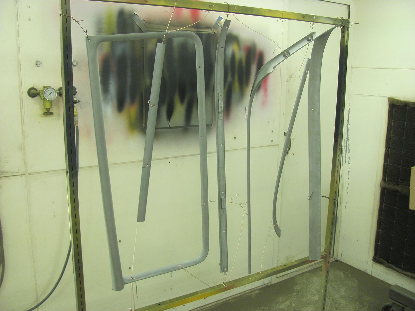
Kyle had finished a bunch of media blasting so they were hung up in the booth to get ready for some epoxy, likely next week....
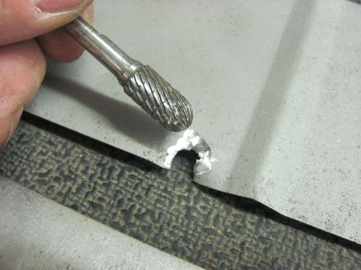
Kyle used the ball end carbide in a die grinder to remove the lower baffle of the core support, so we can get rid of the remaining rust there...
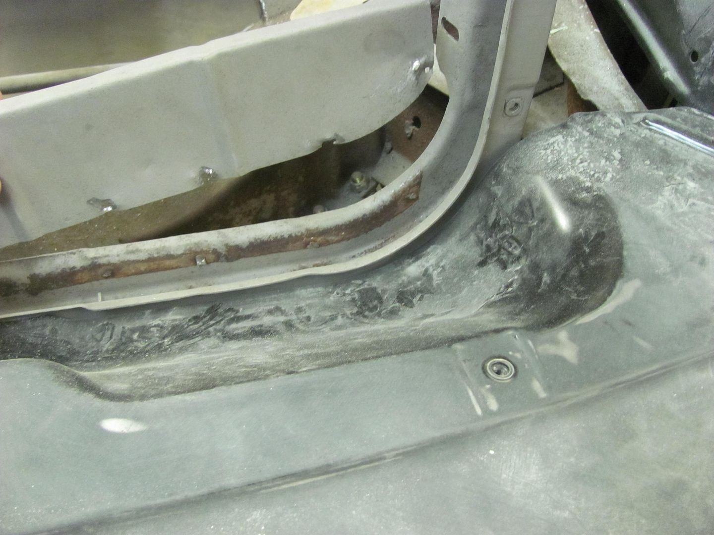
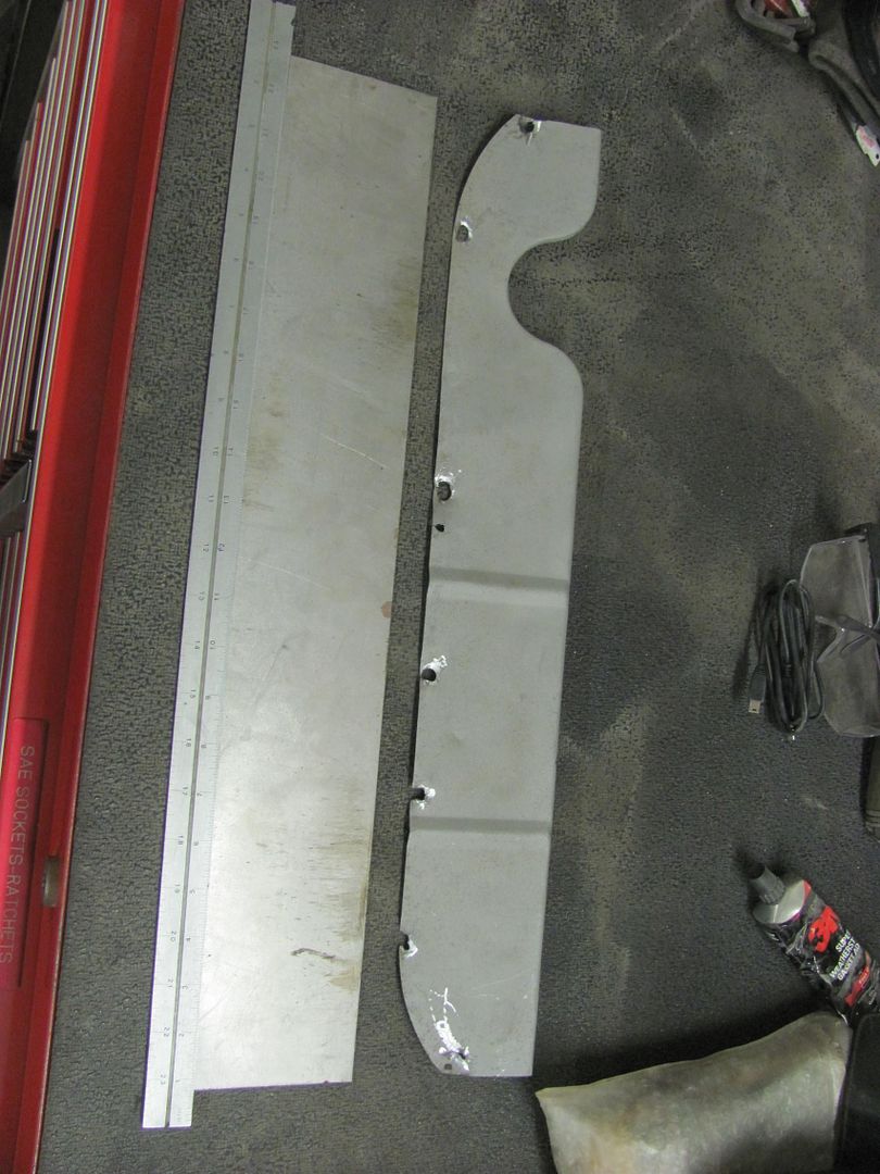
Starting on the replacement piece, we'll get this finished next time..
Everything back in place....
even the top of the tool box...
Kyle had finished a bunch of media blasting so they were hung up in the booth to get ready for some epoxy, likely next week....
Kyle used the ball end carbide in a die grinder to remove the lower baffle of the core support, so we can get rid of the remaining rust there...
Starting on the replacement piece, we'll get this finished next time..
Everything back in place....
Chris_Hamilton
Trying to be the best me, I can be
Robert, I've followed this project for a while now on this forum and one or two others you have posted on. I love your attention to detail. Just curious is this for a customer and roughly how many hours have you got in this?
MP&C
Member
Chris, this is a customer car, and I need to total up some time cards to figure out our running total of hours thus far...
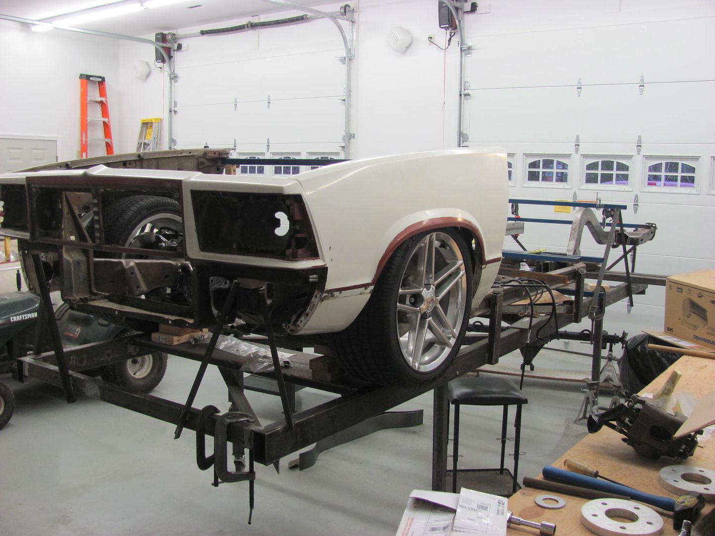
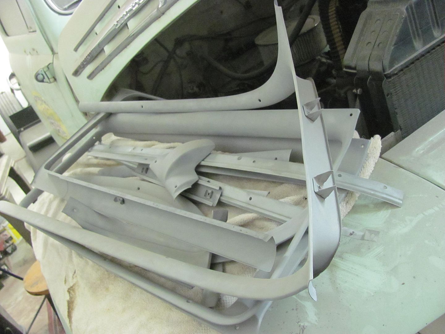
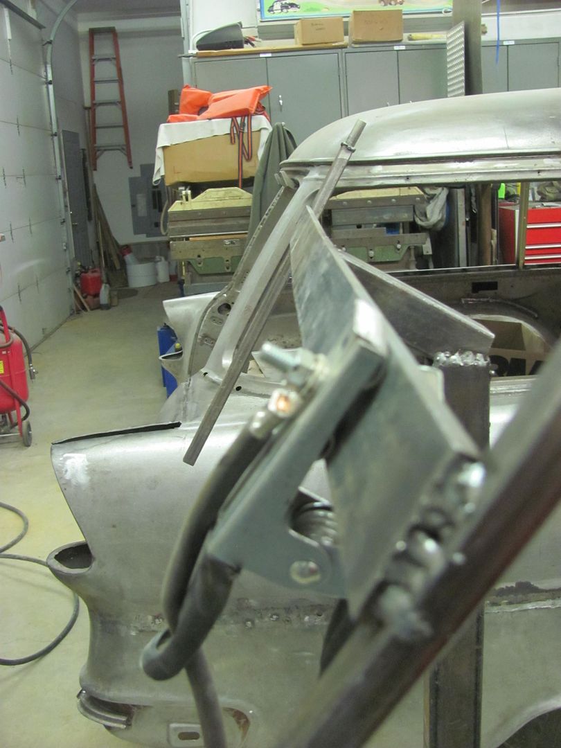
Our Saturday progress had us making more painting fixtures, this time for the rear gates. The lift gate used some square tube and riv-nuts for attachment...
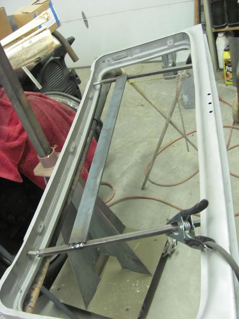
Fixture was made to hold lift gate in same position as on car for spraying...
More blocking....
Tail gate painting fixture....
Then a bit of scuffing to get ready for the next coat of epoxy....
Our Saturday progress had us making more painting fixtures, this time for the rear gates. The lift gate used some square tube and riv-nuts for attachment...
Fixture was made to hold lift gate in same position as on car for spraying...
More blocking....
Tail gate painting fixture....
Then a bit of scuffing to get ready for the next coat of epoxy....
C
Charlie D
This is such a neat and informative post. Would you mind telling us just a little about the welding equipment you use? Do you have a favorite brand of wire that you use most? I am sorry if you have already done that in a prior thread. I just bought my first mig welder and will be checking into how much a small bottle will cost. I watched several utube videos concerning mig welding but my first welds with the flux wire do not look very good. I am hoping that the gas may help a little. I see that you use copper backing plates so I Googled that subject and it looks like those could help out quite a bit on the 18 gauge sheet metal.
Thank you for sharing so much of the fabricating work with the forum. The young man that is assisted you is gaining so much knowledge that can be applied for the rest of his life. Many of us are also acquiring quite a bit of knowledge from your thread.
Charlie D.
Thank you for sharing so much of the fabricating work with the forum. The young man that is assisted you is gaining so much knowledge that can be applied for the rest of his life. Many of us are also acquiring quite a bit of knowledge from your thread.
Charlie D.
MX442
.
Charlie, switching to argon/CO2 gas mix will help out a lot. As an added precaution, flux core creates a lot more fumes. Flux core would be more suitable for outside welding in windy conditions or no access to argon. For sheetmetal, I use .023 wire. Get a scrap fender, and practice. Good luck!
MP&C
Member
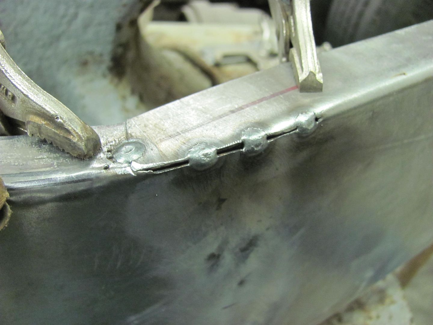
Charlie, I had an L-tec Migmaster 250 until a few months ago. I bought it new, and it was the predecessor to the same machine by Esab. So that puts it close to 25 years old, I figured time for a new one. I now have a Miller 211 mig. The slightly smaller size has allowed me to consolidate most all of my powered welding equipment into one neat stack, a four story welder, if you will. I have used ER70S-6, EZ-Grind, and ER70S-7 wire, in conjunction with argon mix of 75%Argon, 25%CO2, also known as C25 mix. Personally I prefer to weld without the crutch of a copper backer, but fitment inconsistencies will get the best of us, so you do what you have to do..
Overall, I've found that the -6 wire has a bit more proud (height) and also seems to be a bit harder when planishing/grinding. Both the EZ grind and the -7 showed to have better flowout, for a weld that is less proud for less grinding, and also appeared to be softer for easier planishing. Some of the hardness of the -6 may be attributed to the excess volume of the weld. My preference between the three would be the -7, as in addition to the less proud, it also seems to have less of a splatter issue that the EZ Grind seems to be plagued with. Downside is that ESAB Spoolarc 87HP (ER70S-7) is not available in .023 wire and is also not available in anything but 44lb spools, it seems. I've already emailed ESAB to let them know they are missing the boat with all the smaller welders out there in home shops doing bodywork, but apparently their marketing folks know best. Just today I ordered a 44lb spool of the .030 -7, along with some empty 10lb spools to rewind it onto that it will fit my machine. If you look you can find -7 wire in .023 available in some no-name brands, made in a far-away land. Given the questionable quality of other goods that originate there, I'm not so sure to trust that alternate forms of welding wire are nothing more than a label change, so I'll stick with the domestic stuff for now...
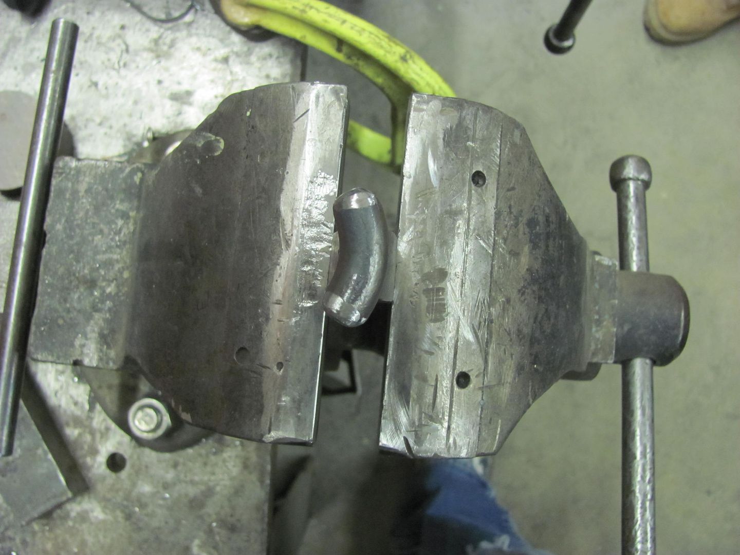
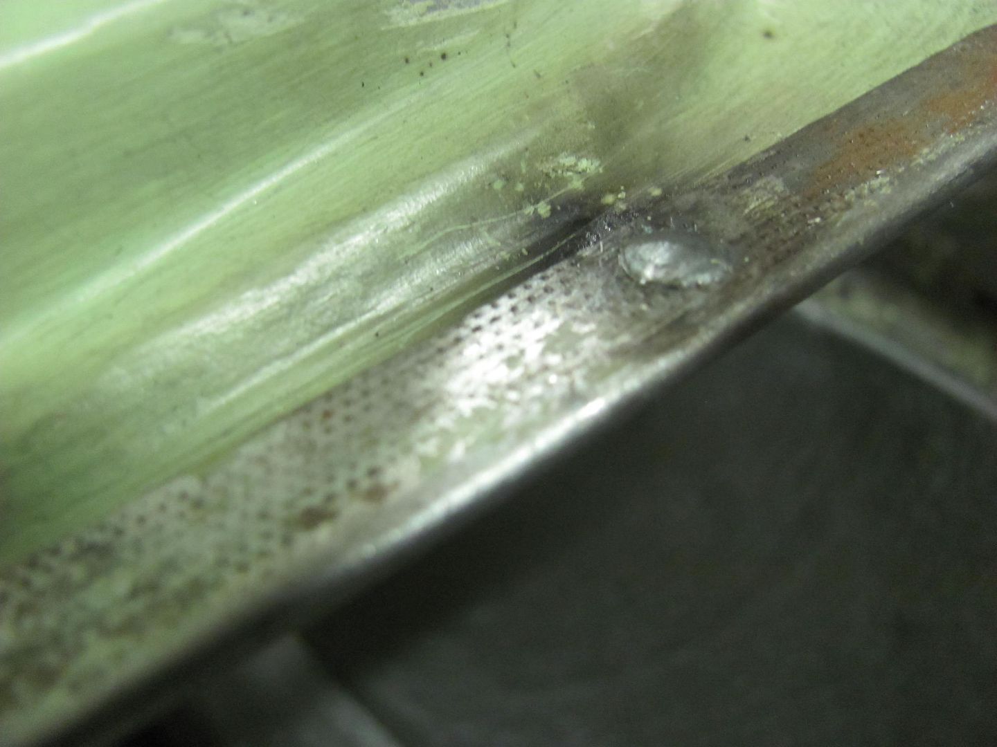
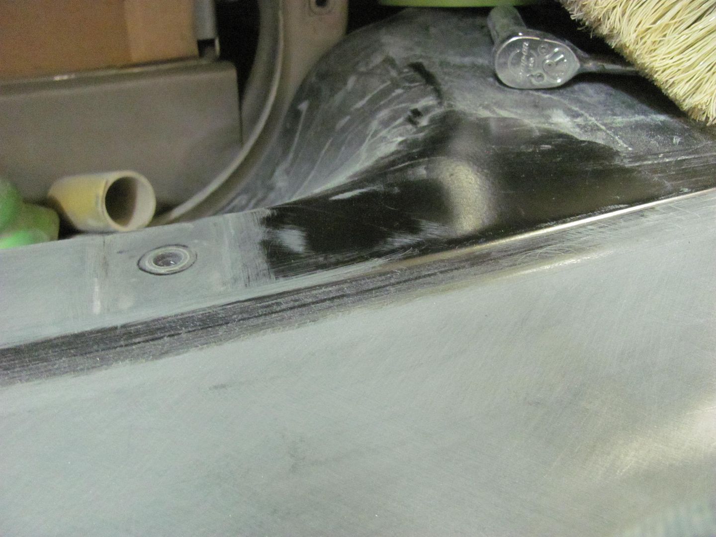
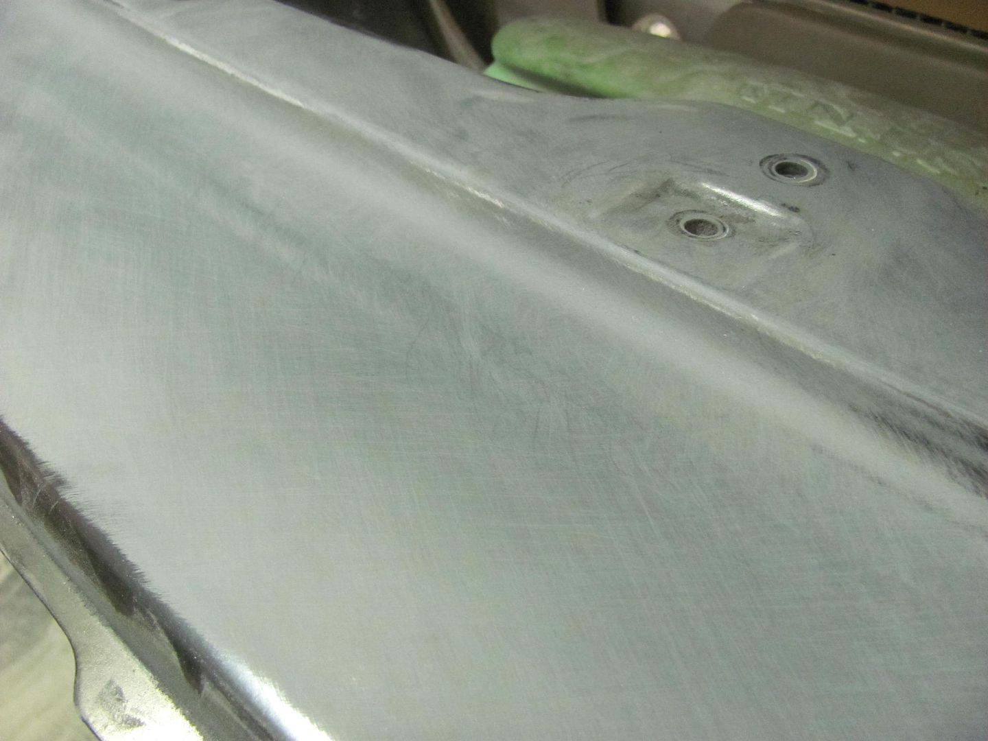
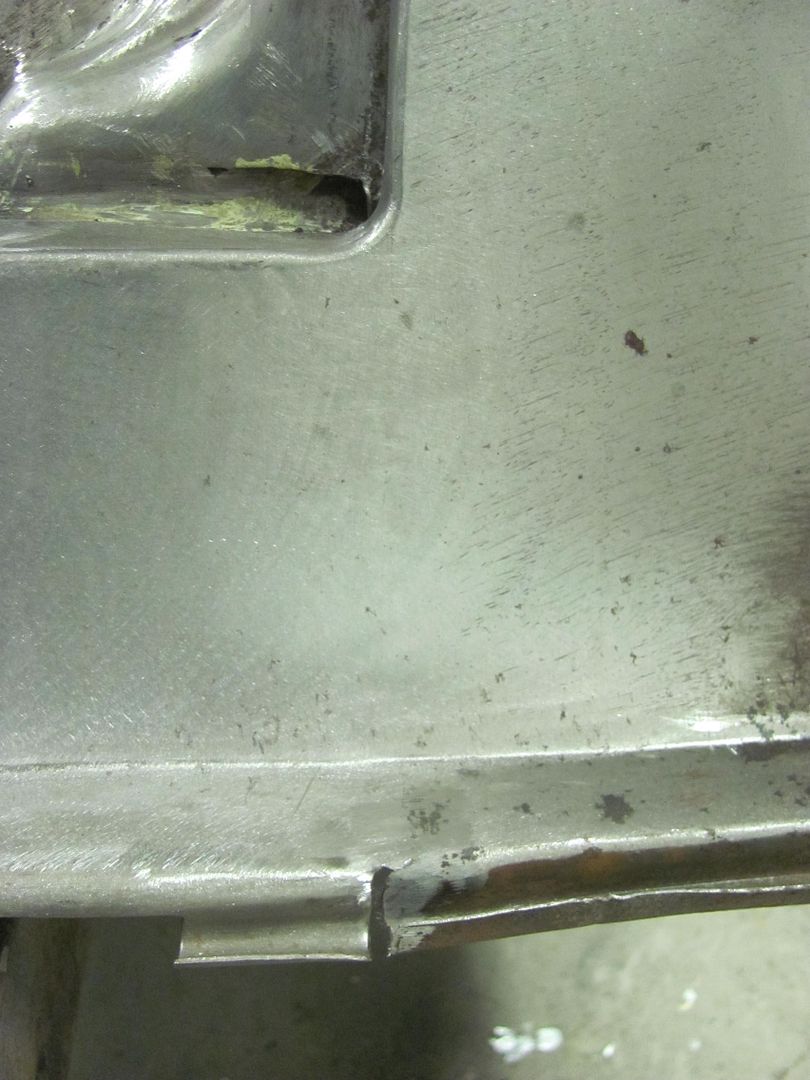
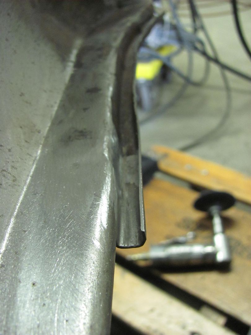
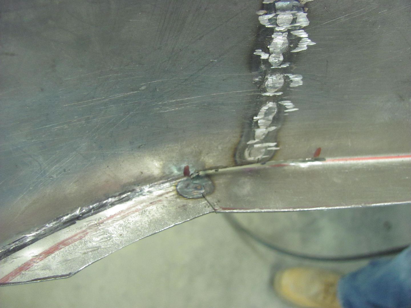
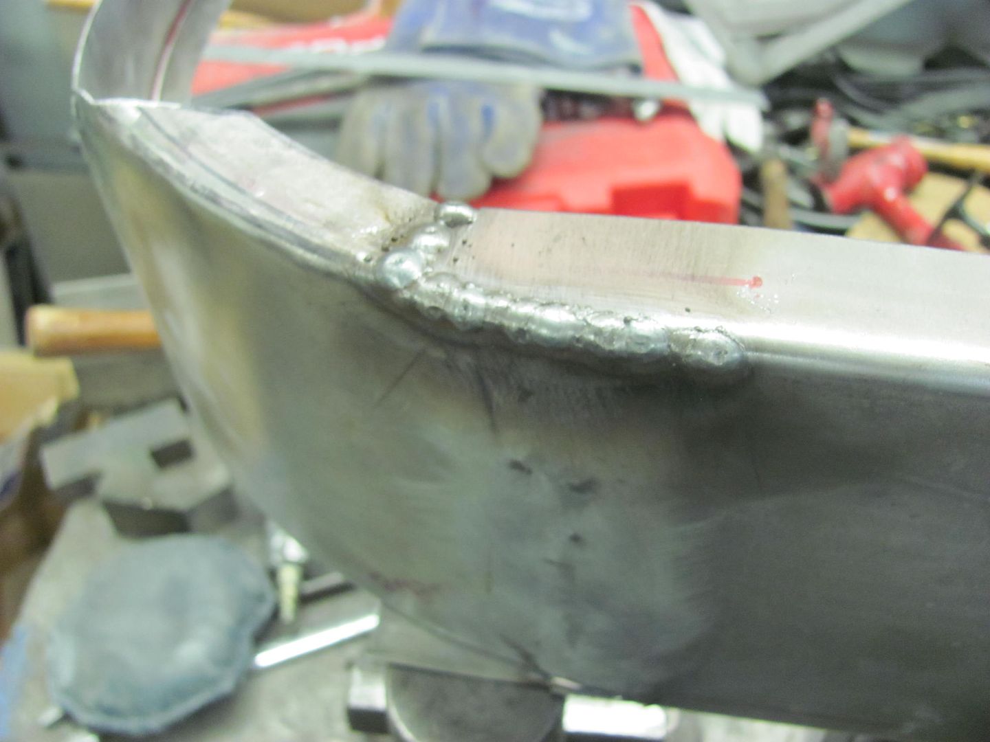
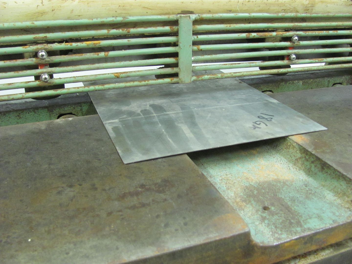
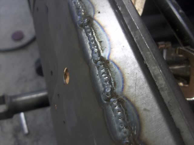
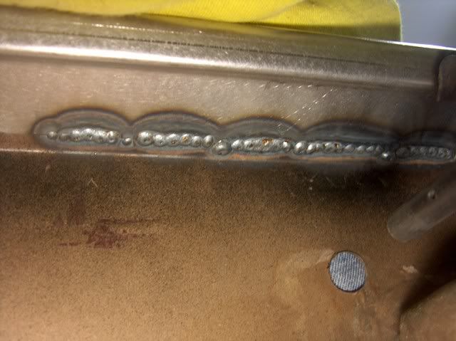
Here are some views to show the results I've seen in the different wires..
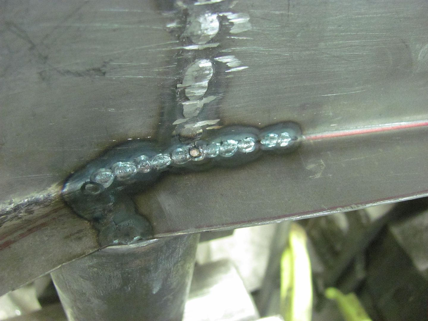
This is an ER70S-6 sample, front and back sides showing the full penetration welds on a Fairlane trunk opening repair...
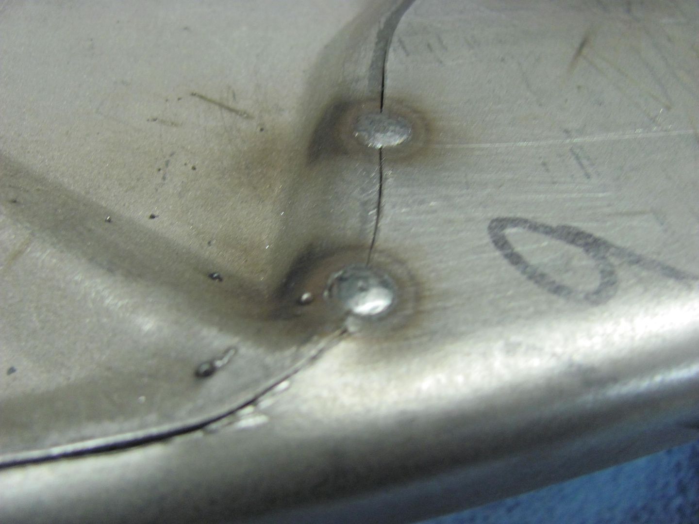
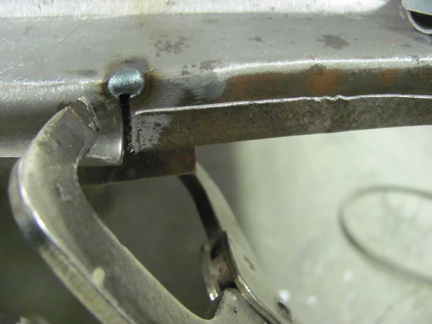
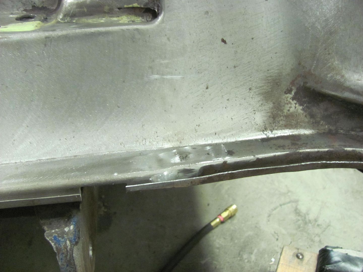
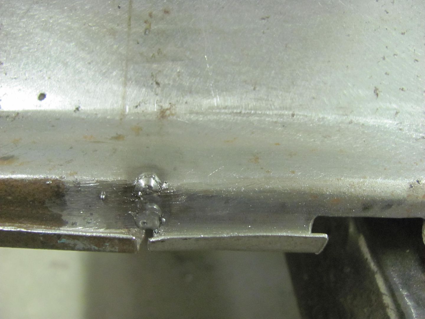
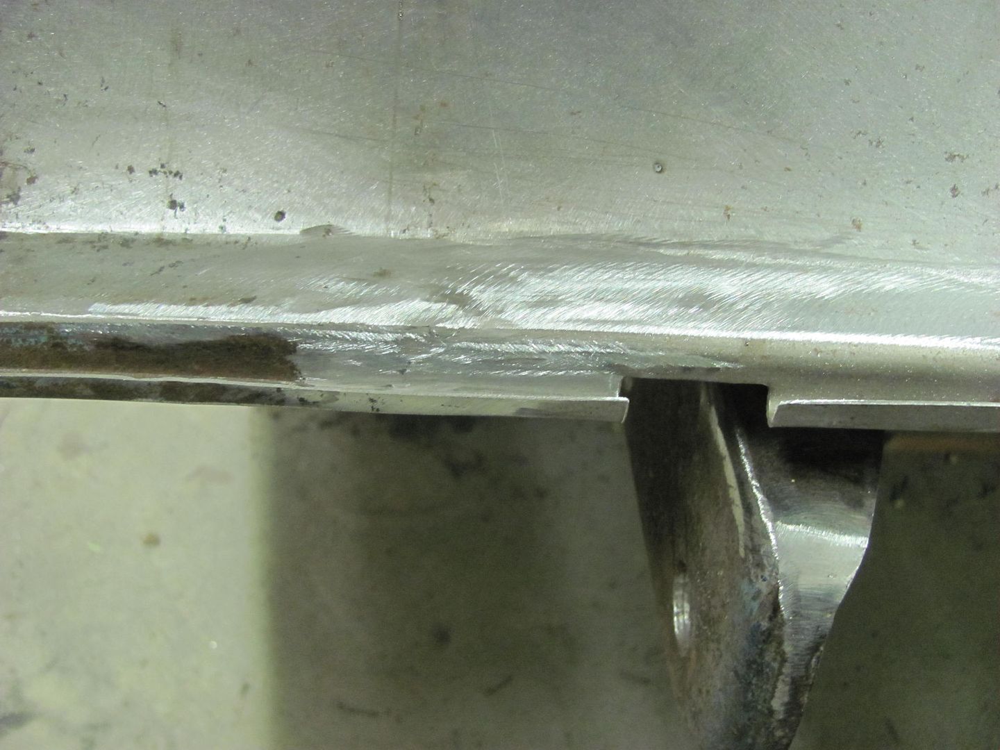
This shows a comparison between the EZ Grind and the ER70S-7:
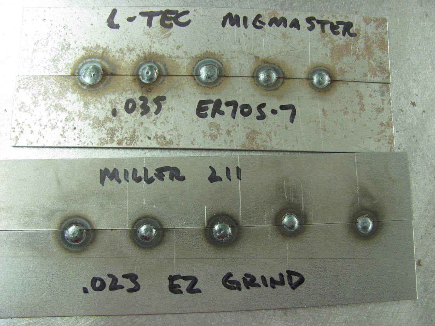
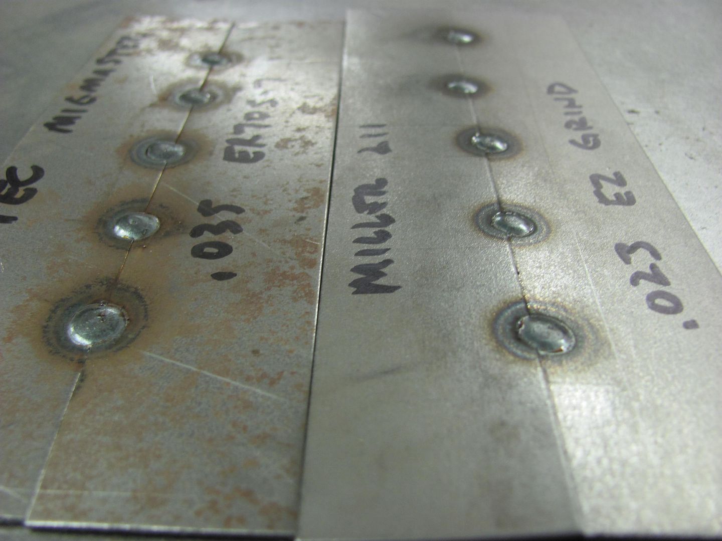
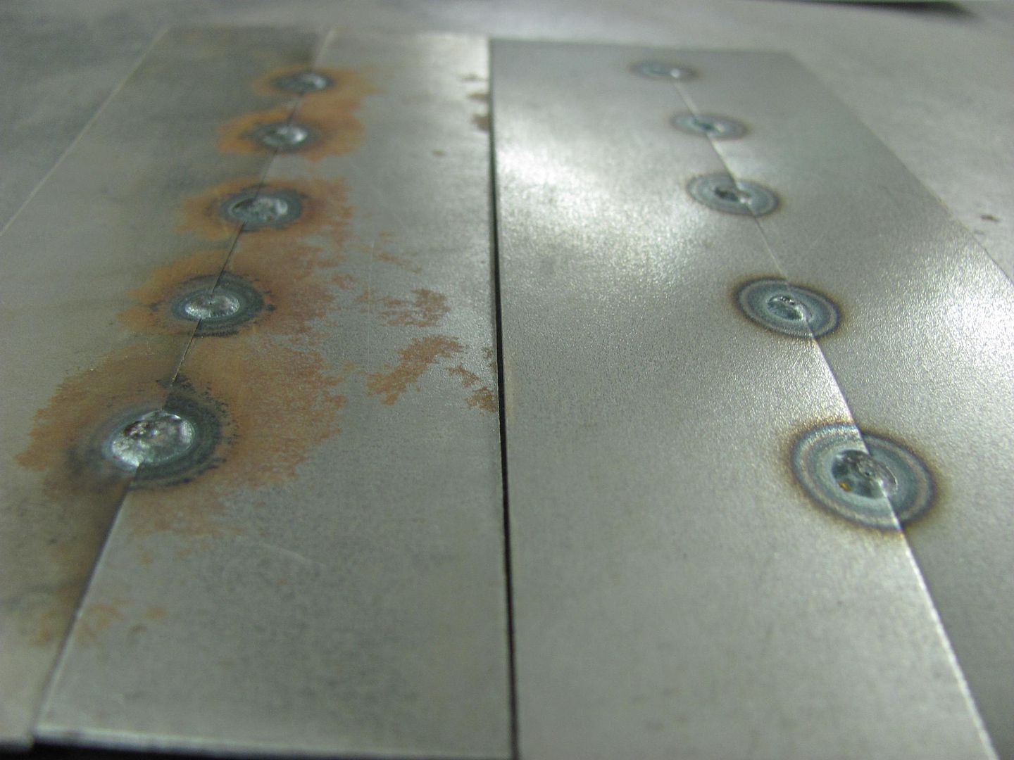
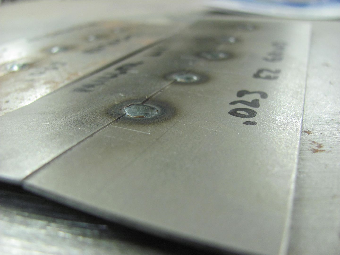
Both versions, .023 EZ grind and the .035 ER70S-7 in the old machine had very similar results. Good wetting, nice flat weld for minimal build, less grinding, less cleanup.
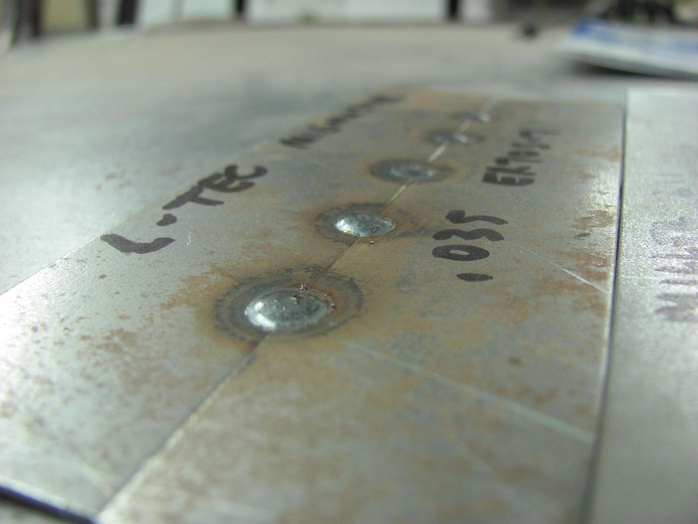
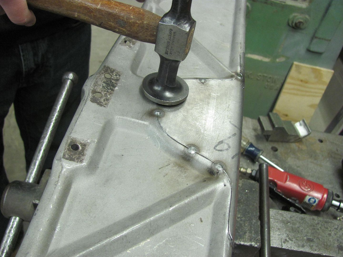
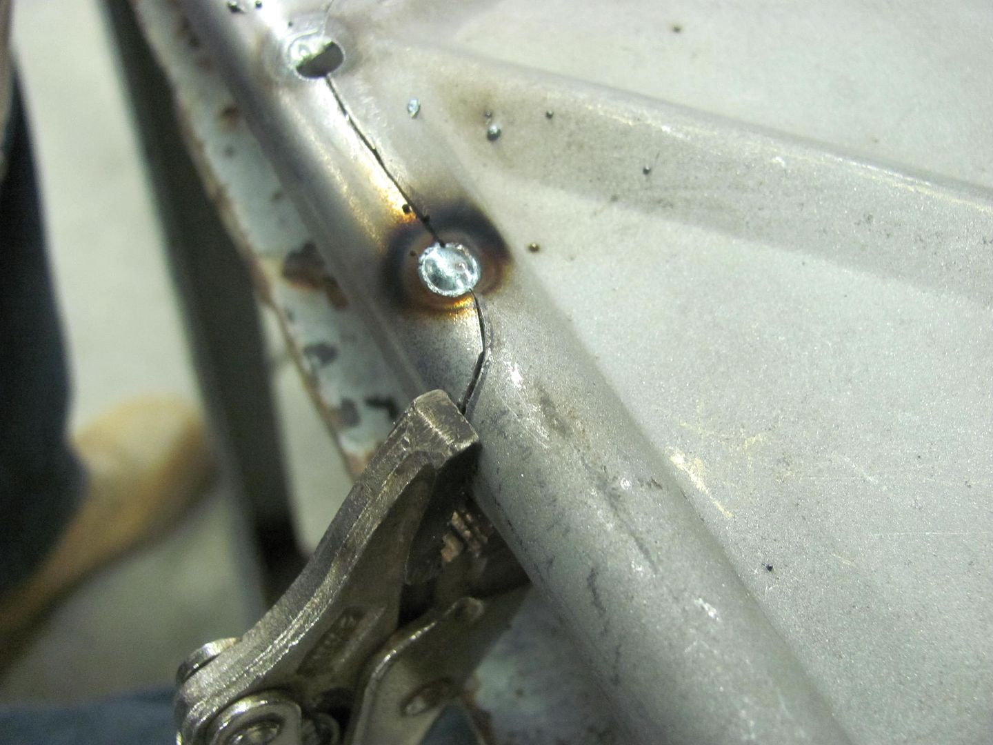
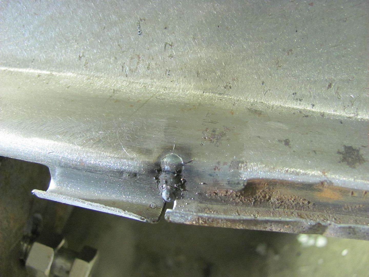
But note on this roof patch seam, with alternating pattern of EZ Grind and ER70S-7, using the same machine, the EZ grind shows more prevalence to splattering.
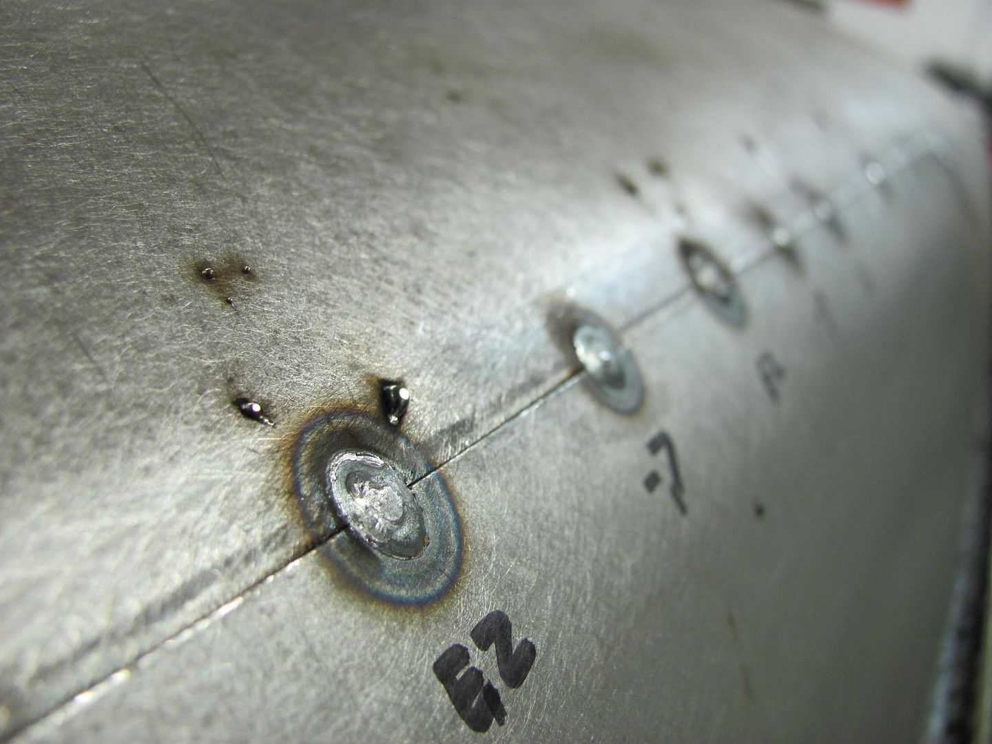
So based on my results, and that the majority of our work is sheet metal, my preference is to use the ER70S-7.
Overall, I've found that the -6 wire has a bit more proud (height) and also seems to be a bit harder when planishing/grinding. Both the EZ grind and the -7 showed to have better flowout, for a weld that is less proud for less grinding, and also appeared to be softer for easier planishing. Some of the hardness of the -6 may be attributed to the excess volume of the weld. My preference between the three would be the -7, as in addition to the less proud, it also seems to have less of a splatter issue that the EZ Grind seems to be plagued with. Downside is that ESAB Spoolarc 87HP (ER70S-7) is not available in .023 wire and is also not available in anything but 44lb spools, it seems. I've already emailed ESAB to let them know they are missing the boat with all the smaller welders out there in home shops doing bodywork, but apparently their marketing folks know best. Just today I ordered a 44lb spool of the .030 -7, along with some empty 10lb spools to rewind it onto that it will fit my machine. If you look you can find -7 wire in .023 available in some no-name brands, made in a far-away land. Given the questionable quality of other goods that originate there, I'm not so sure to trust that alternate forms of welding wire are nothing more than a label change, so I'll stick with the domestic stuff for now...
Here are some views to show the results I've seen in the different wires..
This is an ER70S-6 sample, front and back sides showing the full penetration welds on a Fairlane trunk opening repair...
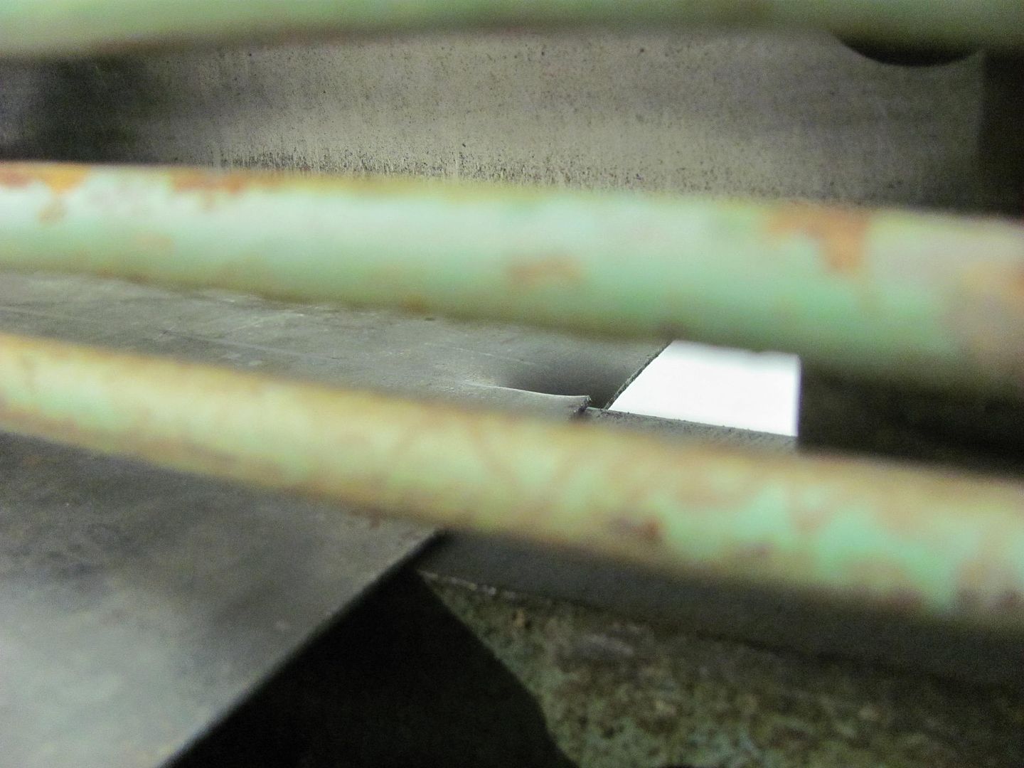
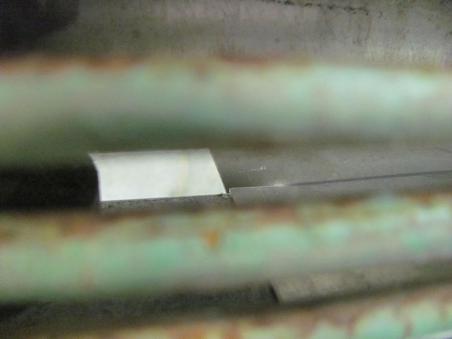
This shows a comparison between the EZ Grind and the ER70S-7:
Both versions, .023 EZ grind and the .035 ER70S-7 in the old machine had very similar results. Good wetting, nice flat weld for minimal build, less grinding, less cleanup.
But note on this roof patch seam, with alternating pattern of EZ Grind and ER70S-7, using the same machine, the EZ grind shows more prevalence to splattering.
So based on my results, and that the majority of our work is sheet metal, my preference is to use the ER70S-7.